Science Arts & Métiers (SAM)
is an open access repository that collects the work of Arts et Métiers Institute of
Technology researchers and makes it freely available over the web where possible.
This is an author-deposited version published in: https://sam.ensam.eu Handle ID: .http://hdl.handle.net/10985/6828
To cite this version :
Matthieu SCHNEIDER, Laurent BERTHE, Maryse MULLER, Rémy FABBRO - A fast method for morphological analysis of laser drilling holes Journal of Laser Applications Vol. 22, n°4, p.5 -2010
Any correspondence concerning this service should be sent to the repository Administrator : [email protected]
A fast method for morphological analysis of laser drilling holes
M. Schneider,L. Berthe, M. Muller, and R. FabbroLaboratoire PIMM (CNRS) ARTS et METIERS ParisTech, 151 Boulevard de l’Hopital, 75013 Paris, France
This paper presents an original method for analyzing laser drilled holes. The so-called Direct Observation of Drilled hOle 共DODO兲 method is introduced and its applications. The hole characterization that’s been made is compared with x-ray radiography and cross-section analysis. Direct Observation of Drilled hole provides instantaneously surface state, geometric shape, as well as recast layer structure, without additional operation. Since no mounting resin is used to embed the sample, the preparation for analysis is simplified and, gives access to a 3D analysis of hole morphology. The principle of this technique consists in positioning the drilling axis on the joint plane of a butt configuration. Surfaces of the two parts of the sample to be joined are polished beforehand, to increase the contact surface, and then holes are drilled in the joint plane. Once the sample is drilled, the two parts are split so that one half of the hole is in each part of the sample. The preparation time of DODO method samples is shorter than the polishing time of the classical method. Moreover the implementation of the DODO method is much easier, for quality control as well as process development in laser drilling. © 2010 Laser Institute of America.
Key words: Laser drilling, morphology, quality control, process development
I. INTRODUCTION
Laser drilled holes are used in aircraft industries to cool parts of engines working under very high temperatures.1–6 The gas comes from the combustion chamber with a high temperature. To prevent a prematurely aging or a partial melt, components must be shielded. Therefore cooling air is blown through drilled holes in turbine components. Because of numerous holes necessary for cooling, processing time has to be as fast as possible.
The principle of laser drilling resides in the focusing of a laser beam of high-power on the workpiece surface, in order to melt and then evaporate the irradiated area. Typically, la-ser intensity of 10 MW cm−2 is used to drill the metallic targets.
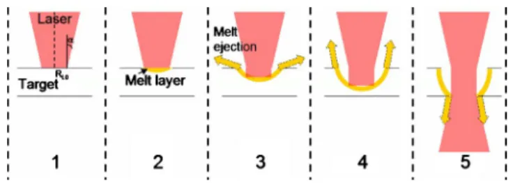
During the experiments, percussion drilling is per-formed. The hole is drilled along the optical axis. Figure 1
schematizes in five main steps the thermodynamic effects that drive the drilling process.
On Fig.1 共1兲, the irradiated target surface is heated by
absorption of laser energy. On Fig. 1 共2兲, a thin layer is
melted. Once the surface temperature gets higher than the vaporization temperature 关Fig.1 共3兲兴, the vapor flow is
nor-mal to the surface. The recoil pressure generated by vaporization,7exerts a force on the melted surface and starts expelling the melt out of the hole located on the side.
On Fig. 1 共4兲, the ejected vapor flow is supersonic.8
Drilling depth is increased and melt ejection becomes verti-cal 关Fig.1 共4兲兴.
In the last sequence, the hole is drilled through 关Fig.1
共5兲兴. The melt is ejected through the hole exit and laser in-teraction stops.
Besides of thermodynamic aspects, absorptivity is modi-fied during the process at 1064 nm, with steel, it increases from 35%9,10 to 80% with incident intensity higher than 10 MW cm−2.11
The drilled hole diameter is in a 0.5 mm range, its depth can reach 20 mm, and recast layer is about 10 m thick. Three main characteristics define the quality of these holes: the surface state around the hole entrance of the drilled part, the hole morphology inside the material 共diameter, taper, shape兲, and the recast layer structure 共thickness, delamina-tion and cracking兲. These features are essential to ensure the cooling flow capability and to increase the lifetime of the part. Without sample preparation, only surface state can be observed. The other characteristics are more difficult to dis-cern since they require a precise and detailed preparation of
Electronic mail : [email protected]
FIG. 1. Schematic representation of laser drilling. RL0is the laser radius in the focal plan and␣the numerical aperture. During drilling, the surface is heated共1兲, melted 共2兲 and vaporized. The vapor flow becomes supersonic and the recoil pressure expels the melt layer out of the hole at the side of the focal spot, first horizontally共3兲 then vertically 共4兲. At the end of drilling, the hole is breaking through共5兲.
the samples, such as cutting and polishing, and/or expensive equipment such as x-ray radiography device.1–3
Because x-ray radiography has a low resolution and longitudinal-section generates measurement errors with few tilts, a statistical analysis of the drilling characteristics ac-cording to inherent laser fluctuations or experimental param-eters is therefore very difficult to achieve. This major draw-back is considered as an obstacle to both industrial development and better understanding of the physical pro-cess involved in laser drilling. Moreover these two tech-niques use specific devices, they cannot be made on laser drilling site, and then require more time, up to several days, to return results after drilling.
This paper describes an original, fast and very simple technique called Direct Observation of Drilled hOle 共DODO兲, allowing the direct observation of the morphology and the recast layer structure of holes drilled by laser which are the main hole features in term of quality. The conven-tional methods, namely, x-ray radiography and cross-section analysis, are summarily described in part 2. Part 3 presents the DODO method, its advantages and drawbacks compared to other techniques.
The holes were produced with a Trumpf HL201P Nd:Yag laser12 with the following operational conditions: 1 ms pulse duration, 20 MW cm−2power density, the spot di-ameter is 320 m in the focal plane. The sample material is 1.4404共316L兲 standard stainless steel.13
II. PRINCIPLE OF CONVENTIONAL METHODS A. X-ray radiography: Nondestructive testing
The radiography is a nondestructive testing method, allowing to watch the shape of the hole drilled in the sample. Its principle is described in Fig. 2. Practically; the drilled sample is located in front of a radiographic paper. The x-ray beam irradiates the whole sample with a normal incidence.
The paper highlights a two-dimensional projection of holes. Figure 3 presents a radiography image of a sample with four holes.
Based on this picture, the global shape, depth and taper of the hole can be determined. Typically, its top diameter is 500 m and its depth is 2 mm. However, recast layer thickness and the presence of possible defects such as delamination and cracks are not clearly seen with the help of this technique.
The accuracy of this method depends on both the resolution and the contrast of the image. The paper quality and the source diameter determine the resolution, which is in best case, in the range of dozens micrometers. The contrast is sensitive to both the exposure time and the sample thickness.
The main advantage of this method is to probe the hole profile without cutting the sample. This nondestructive technique may be used to test a workpiece after drilling. Nevertheless its resolution is lower than that of the other techniques and not allows an measurement of microscopic structure like recast layer thickness. Moreover, the accuracy of measurements such as hole depth depends on the angles between the incidence angle of the drilling axis and the x-ray film.
FIG. 2. Schematic representation of x-ray radiography method.
FIG. 3. Typical image from x-radiography. Four holes are visible.
FIG. 4. Schematic representation of cross-section. Shift共␦兲 is the distance between the longitudinal section and the drilling plane. Tilts are angles between the cross-section plane and drilling plane共␣and兲.
FIG. 5. Image performed with optical microscopy of a cross-section of hole obtained by cross-sectioning technique.
B. Longitudinal-section: Microanalysis
The longitudinal section is the most widespread technique, although it is destructive. This method requires to cut and to polish the sample until the longitudinal-section is located in the drilling axis. The polishing is usually finely performed with a one micron diamond suspension. A chemical solution can be used to reveal the grain boundaries. This technique is very useful in metallurgical analysis, as it allows assessing the material structure such as phase precipitates, grain size, etc. The main advantage of this technique is the accuracy of the measurements in a micrometric scale. In principle, all features of the hole can be measured such as hole profile共diameter, taper, shape兲, as well as recast layer structure such as thickness, delamination and cracking. However, due to the polishing procedure, this method does not ensure accurately the drilling axis is in the longitudinal section. Figure 4 shows a schematic view of these limits: the shift and double tilts between the drilling plane and the longitudinal-section plane. The mounting resin that is used to guarantee sample integrity all along the polishing procedure, reduces the control of the polishing and allows only a 2D analysis of the longitudinal section. Figure
4shows a schematic representation of intrinsic measurement errors due the positioning of the longitudinal section. The measurement error is a combination of one shift共␦兲 and two tilts 共,␥兲 between the drilling axes plane and the longitudinal section. The relative errors can reach 20% and 40% on, respectively, hole diameter and recast layer thickness for ␦=⫾0,1 mm and =⫾1°. Besides the hole shapes are completely change by a␥=⫾0,5°.
Consequently, the tilt does not modify the measurements of small length like recast layer thickness and metallographic observations. However, errors make on measurements of the diameter, depth and taper of the holes are depending of the tilt angles. Figure 5 shows an image performed with optical microscopy of a longitudinal-section of a hole done by this technique. More than the x-ray
radiography, this method is highly time consuming for producing metallurgic samples. Typically, only a few holes a day are analyzed.
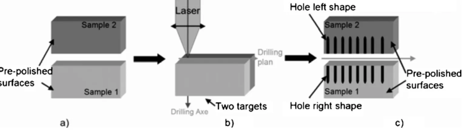
III. DODO: DIRECT OBSERVATION OF DRILLED HOLE This technic is meant to be implemented on prepared samples. Its principle described in Fig.6consists in position-ing the drillposition-ing axis on the joint plane of a butt configuration. Surfaces of both samples are beforehand polished 关see Fig.
6共a兲兴 to improve their contact, and then holes are drilled in such a manner that their axis are localized in the joint plane 关Fig.6共b兲兴. Once the sample is drilled, the two parts are split and a half-hole appears in each one, as can be seen on Fig.
6共c兲.
The following procedure is used: the parts are performed on a Struers TegraPol 31. The polishing starts at 80 grit, with an adhesive back disk SiC paper, and reaches 3 m using a DiaPro diamond suspension. Then the two parts are joined, positioned and gripped in a vice. The laser is positioned on the joint plane and holes are drilled.
Consequently, DODO ensures the merging of the drilling axis and of the analysis plane, and thus ensures measure-ments of the depth and of the conicity of the hole. Figure7
shows an image of the two samples drilled and split. The figure gives clear evidence of the morphology and the recast layer thickness of the twenty holes. The reproducibility and the evolution of the hole characteristics according to the ex-perimental parameters can be analyzed in one glance.
Figure 8 shows a single hole drilled with the DODO technique. Because no mounted resin was used, the surface state of the inner wall and the 3D shape of the both side of the hole can be analyzed.
Besides, the quality of this method may be checked di-rectly. If the drilling axis is not positioned precisely in the joint plane, the half-holes on each part won’t be symmetrical; moreover a top view of the assembled parts will show it.
FIG. 6. Principle of the DODO technique.共a兲 Two samples are polished. 共b兲 They are drilled in butt configuration. Drilling is made on the interface between the two samples.共c兲 After drilling, the samples are split and two half-holes are revealed on each half of the samples.
FIG. 7. Optical image of the two samples drilled with the DODO method. The half-holes appear on each sample. All the hole features共diameter, etc.兲 can be measured and a statistical study is realizable.
The quality of the sample preparation may also be checked. The melted metal injected between the two parts during laser drilling will be revealed after the splitting of the sample. It will show that the two parts were not well merged. Figure 9 presents the result when a 100 m thick metallic layer is inserted between the two parts on the left side. The melt metal is injected between the interfaces and the six holes on the left have their shapes distorted that reveals here the misuse of the method.
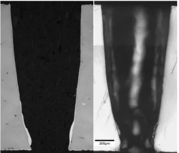
Figure 10 shows two holes drilled with the same laser parameters. The left image is obtained through a conven-tional longitudinal-section analysis, the right one is obtained through the DODO method. The hole shapes are exactly the same, the results are not modified by the method. Therefore one can conclude that the presence of an interface on the drilling axis does not change the thermal diffusion or the process.
The main advantage of this technique is that results can be returned within relatively short delay, compared to previ-ous methods mentioned in Part II. The analysis plane is not positioned on holes 共like in longitudinal section兲 since the
holes are drilled on the analysis plane共like in DODO兲, hence the splitting of the sample reveals a fast overview of the hole drilled in one glance. Moreover, the interpretation can be made on the drilling site which allows making faster statis-tical studies on industrial site for better development, control and repeatability of the process. More precise measurements can be made with optical devices like microscope or even a numerical scanner on hole characteristics. By comparison, with a longitudinal-section analysis results are obtained in a half day on one single hole with one polishing procedure, whereas using DODO method 70 holes are analyzed in the same polishing procedure time with less error measurement. Moreover a misused of the procedure is clearly revealed by the DODO method itself. In term of investment, a polishing machine is used like for the conventional longitudinal-section analysis.
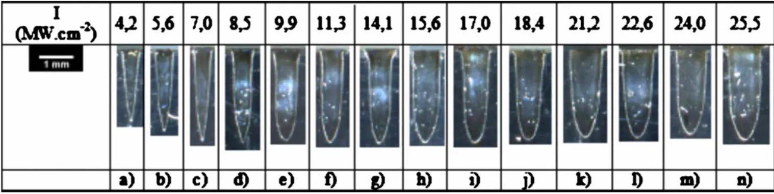
Figure11shows the hole profile evolution as a function of the laser intensity. Holes drilled have two different shapes called V and U profiles. For the holes drilled with an inten-sity below 8 MW cm−2the corresponding profile is close to a V. For higher intensities holes have an U profile. These observations have helped to complete the Semak and Matsu-nawa model7with a new relation between the hole diameter and the melt velocity.
IV. SUMMARY
This paper presents an original analysis technique called Direct Observation of Drilled hOle 共DODO兲 which allows characterizing laser drilled holes. DODO method allows measuring all hole characteristics like the hole morphology 共diameter, taper, profile兲, and the recast layer structure 共thickness, delamination, and cracking兲. Compared to tradi-tional methods DODO ensures control of the analysis plane since the holes are drilled directly on it. Consequently, no operation such as cutting and polishing are necessary after the drilling. An interpretation of the result can be made on
FIG. 8. Optical image of two complementary half-holes revealed by DODO technique.
FIG. 9. Images performed with optical microscopy of hole revealed by DODO method. A 100 m thick metallic layer was inserted between the two samples on the left side.
FIG. 10. Comparison between cross-section image共on the left hand side兲 and DODO image共on the right hand side兲. Images are obtained from two holes drilled with the same experimental parameters.
drilling site. Furthermore DODO suits especially well rou-tine test applications in a mass production context as it is less expensive, easier and faster to apply than the current state-of-the-art techniques of the field. Finally, fundamental inter-est is found in the DODO technique as it can provide deeper insight into the complex physical aspects of laser drilling, by giving access to fine features of hole profile evolution with laser irradiation parameters.
ACKNOWLEDGMENTS
This work has been supported by Commissariat à l’Energie Atomique 共CEA-France兲 and Trumpf Laser for HL201P Laser facility and Agence Nationale pour la Recher-che.
1A. Horn, R. Weichnehain, S. Albrecht, E. W. Kreutz, J. Michel, M. Nies-sen, V. Kostrykin, W. Schulz, A. Etzkorn, K. Bozin, E. Lugscheider, and R. Poprawe, “Microholes in Zirconia coated Ni-super alloys for transpi-ration cooling of turbine blades,” Proceedings of SPIE-High-Power Laser Ablation III, edited by Claude R. Phipps共2000兲, Vol. 4065; pp. 218–226. 2M. Jeandin, P. Forget, P. Lechervy, and D. Valera, “Laser drilling appli-cation to ceramic coated alloy,” Mater. Manuf. Processes 4, 263–272
共1989兲.
3K. T. Voisey and T. W. Clyne, “Laser drilling of cooling holes through plasma sprayed thermal barrier coatings,”Surf. Coat. Technol. 176, 296–
306共2004兲.
4C. A. McNally, J. Folkes, and I. R. Pashby, “Laser drilling of cooling holes in aeroengines: state of the art and future challenges,”Mater. Sci. Technol. 20, 805–813共2004兲.
5R. Poprawe, I. Kelbassa, K. Walther, M. Witty, D. Bohn, and R. Krewinkel, “Optimising and manufacturing a laser-drilled cooling hole geometry for effusion-cooled multi-layer plates,” Proc. of ISROMAC-12, Paper No. 20091, Honolulu, USA, 2008.
6I. Kelbassa, P. Albus, J. Dietrich, and J. Wilkes, “Manufacture and Repair of Aero Engine Components using Laser Technology,” Proc. of PICALO, Paper No. 405, Beijing, China, 2008.
7V. V. Semak and A. Matsunawa, “The role of recoil pressure in energy balance during laser materials processing,”J. Phys. D 30, 2541–2552
共1997兲.
8M. Schneider, R. Fabbro, L. Berthe, and M. Muller, “Gas investigation on laser drilling,” J. Laser Appl.共to be published兲.
9F. Dausinger and J. Shen, “Energy coupling efficiency in laser surface treatment,”ISIJ Int. 33, 925–933共1993兲.
10A. Mahrle and E. Beyer, “Hybrid laser beam welding-classification, char-acteristics, and applications,”J. Laser Appl. 18, 169–180共2006兲.
11M. Schneider, L. Berthe, R. Fabbro, and M. Muller, “Measurement of laser absorptivity for operating parameters characteristic of laser drilling regime,”J. Phys. D 41, 155502共2008兲.
12M. Schneider, R. Fabbro, L. Berthe, L. Landai, M. Nivard, and P. Lau-rens, “Parametric study of drilling with new innovative laser source: ap-plication to percussion regime,” Proc. ICALEO’04, San Francisco, USA, 共2004兲, pp. 540–546.
13M. Schneider, M. Muller, R. Fabbro, and L. Berthe, “Study of hole prop-erties in percussion regime with a new analysis method,” Proc. ICA-LEO’06, Scottsdale, USA共2006兲.