Combination of electrografting and layer-by-layer deposition: an
efficient way to tailor polymer coatings of (semi)-conductors{
Aure´lia Charlot, Sabine Gabriel, Christophe Detrembleur, Robert Je´roˆme and Christine Je´roˆme*
Received (in Cambridge, UK) 7th August 2007, Accepted 14th September 2007First published as an Advance Article on the web 26th September 2007 DOI: 10.1039/b712130j
This communication reports on a novel, simple and highly versatile concept, which consists in combining the advantages of two complementary and relevant techniques (i) electrograft-ing and (ii) layer-by-layer deposition process with the goal to tailor strongly adhering coatings to (semi)-conducting surfaces imparting them with tunable specific properties.
For many years, a steadily increasing attention has been paid to the preparation of strongly adhering polymer coatings onto solid inorganic surfaces. In this respect, electrografting is a very simple one-step procedure to produce polymer films tightly attached to substrates.1This technique has the advantages of reaching a strong adhesion by chemisorption of the coating to the surface and of being applicable to a wide variety of conductors, including metals, alloys, carbon, ITO-glass and semiconductors.2 This method,
while powerful, has some limitations since it is only applicable to (meth)acrylate monomers and not to protic species, that may limit the panel of the final coatings properties. Moreover, because the chemical process of electrografting is stopped by non-controlled termination reactions and the poly(meth)acrylate films are insulating, the film thickness is limited (,100 nm). Therefore, the combination of electrografting and layer-by-layer (LbL) deposition appears as a promising strategy to overcome these limitations. The attractiveness of the LbL technology is that (i) it is a simple and versatile method that consists in making a multilayer thin film based on the alternate deposition of oppositely charged polyelectrolyte layers, (ii) it can be used with any type of functional polyelectrolytes allowing the surface properties to be tuned by a appropriate choice, and finally (iii) it allows the elaboration of coatings with tailored architecture and thickness at the nanoscale.3 A considerable attention continues to be attributed to the preparation of new coatings by LbL deposition such as the elaboration of ultrathin films by using click chemistry.4However, when applied to uncharged inorganic substrates, the LbL process requests a pretreatment of the surface allowing electrostatic interactions with the first charged layer. Simple dipping in a chelating positively charged polyethyleneimine (PEI) solution might be sufficient for appropriate substrate and less demanding applications.5 However, given the PEI–substrate interaction is uncontrolled, long term durability of the entire multilayer films requires a strong specific anchoring layer, such as provided by
electrografting.1The novel concept, illustrated here for n-doped silicon and stainless steel substrates, consists of the electrografting of poly(N-succinimidyl acrylate) (PNSA) chains, followed by a hydrolysis step to provide a negatively charged anchoring layer for the preparation of multilayer polyelectrolyte films by LbL deposition (Scheme 1).
The first step of the process relies on the electrografting of N-succinimidyl acrylate (NSA) by cathodic polarization in a DMF solution of tetraethylammonium perchlorate.{ The electrochemical observations from voltammograms recorded onto n-doped silicon and stainless steel (see ESI) clearly indicate that PNSA chains are chemisorbed (grafted) as previously reported.2 PNSA is a very
attractive functional polymer since by simple base-catalyzed hydrolysis reaction, a poly(acrylic acid) (PAA)-bound surface is obtained. Thereby, such PNSA chains grafted onto conductive and semi-conductive substrates were hydrolyzed in aqueous sodium hydroxide solution (pH = 8.5) during 12 h to give the negatively charged carboxylate form. The presence of the PNSA chains on the stainless steel surface, after intensive washing of the substrate in dried DMF, a good solvent for PNSA, and thus the success of the hydrolysis and persistence of the hydrolyzed layer on the substrate, have been confirmed by ATR-FTIR analysis of the accordingly modified conducting surface. Indeed, the ATR-FTIR spectrum (Fig. 1(A)) displays the main absorption bands characteristic of grafted PNSA, i.e. the CLO stretching at 1738, 1778 and 1814 cm21, assigned to the succinimidyl carbonyl group and the C–N vibration at 1215 cm21. The spectrum (Fig. 1(B)), recorded after hydrolysis, reveals a total disappearance of these absorption bands accompanied by the appearance of new signals: a broad band at 1596 cm21and thin bands aty1458 and 1418 cm21, which are consistent with the grafted carboxylate species. An additional evidence for the presence of unprotonated PAA on the substrate is the respective changes in contact angles. The 63 ¡ 2u contact angle measured for the PNSA-bound surface before immersion in the aqueous sodium hydroxide solution changes to 45 ¡ 3u after the hydrolysis step, as a result of the formation of the more hydrophilic carboxylates grafted to both types of surfaces. The second step of the process consists in using such electrografted PAA-salt chains onto stainless steel and silicon substrates as strongly attached polyanions to build durable and stable multi-layer polyelectrolyte films. Polycations and polyanions were deposited onto the negatively charged grafted-substrate by the classical alternative dipping method. Two different systems were considered to validate the concept presented in this paper: (i) one from synthetic polyelectrolytes: [poly(allylamine) hydrochloride (PAH)/poly(sodium 4-styrene sulfonate) (PSS)]n, which is probably
presently the best characterized system3and (ii) one from natural
Center for Education and Research on Macromolecules (CERM), University of Liege, B6 Sart-Tilman, B-4000, Liege, Belgium. E-mail: c.jerome@ulg.ac.be; Fax: 32 4366 3497; Tel: 32 4366 3491 {Electronic supplementary information (ESI) available: Fig. S1: Voltammograms recorded onto stainless steel for the reduction of NSA in DMF–TEAP. See DOI: 10.1039/b712130j
COMMUNICATION www.rsc.org/chemcomm | ChemComm
polysaccharides: [chitosan (chit)/hyaluronic acid (HA)]nwhich, due
to their unique biological properties, may allow the development of bioactive coatings.6The final polymer film prepared from the
chemisorbed unprotonated PAA chains followed by the LbL deposition of polyelectrolytes is schematically represented in Scheme 1.
The ATR-FTIR analysis of the two different final coatings, represented in Fig. 1(C) and (D), are consistent with the formation of PAA/(PAH/PSS)n and PAA/(chit/PHA)n films respectively.
Indeed, Fig. 1(C) shows the distinctive absorption bands of PAH at 3450 cm21(N–H stretching) and at 2838 and 2920 cm21(C–H stretching). The PSS is characterized by aromatic CLC stretching bands at 1041 and 1000 cm21. Fig. 1(D) depicts absorption bands at 1636 cm21(N–H angular deformation of chitosan and –CO22
of HA) and at 1070 cm21 (skeletal vibration C–O stretching, characteristics of the saccharide structure of chit and HA), which successfully confirms the construction of the PAA/(chit/HA)n
coating from grafted stainless steel.
UV-visible spectroscopy was used to monitor the LbL assembly process of (PAH/PSS)n from the PAA-grafted stainless steel.
Usually, the absorption of the polyelectrolyte layers is detected using UV-vis absorption spectroscopy.5Nevertheless, this
techni-que can only be applied to transparent supports and is thus not suited to opaque substrates such as those used in this work. UV-vis spectroscopy was thus applied in total reflectivity instead of absorbance mode. The experimental data were then converted to
arbitrary units of absorbance by a mathematic operation: 2log (R/ R0); where R0 corresponds to the reflection coefficient of the
uncoated electrografted-stainless steel substrate and R represents the total reflection of the electrografted-stainless steel substrate coated by a (PAH/PSS) bilayer. Fig. 2 shows the resulting UV-vis absorption spectra recorded after each deposition of a (PAH/PSS) bilayer (up to eight bilayers) onto stainless steel. This figure shows an increasing absorption band at 224 nm (corresponding to the aromatic ring of PSS) with the number of bilayers, which proves the success of the formation of the multilayered film from the strongly attached PAA polyanion. The inset of Fig. 2 clearly evidences a linear increase of the absorbance of stainless steel-supported multilayer (PAH/PSS)nfilm at 224 nm with the number
of deposited bilayers, n. This linearity indicates that the same amount of (PSS/PAH) bilayers was deposited at each LbL cycle. This linear growth observed with PAH and PSS is consistent with the literature data7and shows that the grafted PAA is suitable for the anchoring of multilayer polyelectrolyte film. The success of the building of the multilayered polyelectrolytes from grafted-stainless steel and n-doped silicon substrates has also been confirmed by ellipsometric measurements, using polysaccharides as models.
Scheme 1 Schematic representation of the formation of a coating resulting from the combination of electrografting and layer-by-layer deposition processes.
Fig. 1 ATR/FTIR spectra of PNSA (A), PAA (B), PAA/(PAH/PSS)n (C) and PAA/(chit/HA)n(D) on stainless steel.
Fig. 2 UV-vis absorbance spectra of layer-by-layer assembly of [PAH (5 g L21)/PSS (5 g L21)]
nin pure water (with n = 1–7) deposited onto PAA salt-grafted stainless steel. Inset: evolution of the absorbance at lmax= 224 nm vs. the number of deposited bilayers.
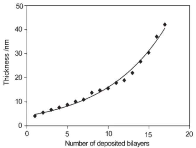
Fig. 3 represents the evolution of the (chit/HA)n multilayer
thickness in the dry state, deposited from the negatively charged PAA grafted-silicon. We solubilized polysaccharides in 0.1 M NaCl since increasing the salt concentration is well known to lead to increased film thickness.8Fig. 3 shows that the total thickness increases in a non-linear fashion vs. the number of deposited bilayers. The non-linear evolution can be explained by the known exponential growth of most multilayered polysaccharides.6 By
extrapolation, Fig. 3 indicates a thickness of approximately 5 nm for the corresponding uncoated grafted PAA-salt film, which is in good agreement with previous data.9Moreover, from Fig. 3, we can note that the deposition of the first (chit/HA) bilayer does not seem to increase the thickness, which could be due to a possible partial penetration of the first deposited (chit/HA) bilayer within the grafted PAA chains. A similar exponential thickness evolution was also observed for the LbL deposition onto PAA-grafted stainless steel (data not shown). UV-vis and ellipsometric experiments evidenced the success of the construction of multilayer films from PAA polyanions electrografted on both stainless steel and silicon substrates. Additionally, the growth (linear or exponential depending on the nature of polyelectrolytes) and consequently the thickness of the final coating can easily be tailored and controlled at the nanoscale.
In conclusion, the electrografting of the easily prepared NSA, followed by a base-catalyzed hydrolysis step provides a novel and well-suited anchoring layer for LbL deposition. The combination of both simple techniques, on one hand, constitutes a very relevant way to overcome the major limitations of electrografting, i.e. control of the thickness and diversity of the coatings, and on the other, is applicable to a wide range of (semi)-conducting surfaces
thanks to the versatility of the electrografting method. This strategy which relies on the use of the electrografted PAA chains as the first strongly adhering polyanion layer for the building of long-term stable multilayer films is thus general. Such a concept was illustrated here by using well-known model polyelectrolyte systems but we can expect to extend it to other ionic polymers and to other types of surfaces, with the purpose to tune the final surface properties, while preserving adhesion of the organic coating.
A. C. gratefully acknowledges the Region Wallonne and ARCELOR-Mittal for a post-doc fellowship at the University of Lie`ge in the frame of the BIOCOAT program. S. G., C. D. and C. J. are indebted to the IAP (VI-27) ‘‘Functional Supramolecular Systems’’ for financial support. C. D. is ‘‘Chercheur Qualifie´’’ by the F.N.R.S., Belgium.
Notes and references
{The NSA (0.1 M when used as the anchoring layer for the LbL deposition and 1 M for the ATR-FTIR characterization) was electro-polymerized according to the procedure detailed in ref. 2. The used working electrodes were stainless steel (304 2R, Arcelor Research Industry Liege (ARIL)), and n-doped silicon wafers, with a specific electric resistance of 0.004–0.005 V cm (ACM). The samples were characterized by ATR-FTIR (attenuated total reflection Fourier Transform IR, Thermo Nicolet ContinummTM) with a Ge crystal. Contact angles of water were measured 30 s after the drop deposition on the surfaces (Digidrop equipment). Poly(sodium 4-styrene sulfonate) (PSS) (Aldrich, Mw= 70 000 g mol21), PAH (Aldrich, Mw= 15 000 g mol
21
), HA (ARD Pomacle France, Mw= 200 000 g mol21), chitosan (Primex, M
w= 70 000 g mol21) were used without further purification. Each polyelectrolyte was solubilized at 5 g L21 in pure water or 0.1 M NaCl. Ellipsometry was carried out using a GES-SOPRA ellipsometer in the UV-visible-NIR (250–1000 nm) range at 75u angle of incidence. The used refractive index for organic coating was 1.465. UV-vis experiments were recorded using a Perkin-Elmer spectrophoto-meter (Lambda 650S).
1 (a) C. Je´roˆme and R. Je´roˆme, Stimuli-responsive Polymeric Films and Coatings, ed. M. W. Urban, ACS Symp. Ser. 912, Washington DC, 2005, ch. 6, p. 84; (b) G. Deniau, L. Azoulay, P. Jegou and G. Le Chevallier, Surf. Sci., 2006, 600, 675; (c) S. Palacin, C. Bureau, J. Charlier, G. Deniau, B. Mouanda and P. Viel, ChemPhysChem, 2004, 5, 1468.
2 (a) C. Je´roˆme, S. Gabriel, S. Voccia, C. Detrembleur, M. Ignatova, R. Gouttebaron and R. Je´roˆme, Chem. Commun., 2003, 2500; (b) S. Gabriel, A.-S. Duwez, R. Je´roˆme and C. Je´roˆme, Langmuir, 2006, 23, 159–161.
3 (a) G. Decher, Science, 1997, 277, 1232; (b) Multilayer thin films: Sequential Assembly of Nanocomposite Materials, ed. G. Decher and J. B. Schlenoff, Wiley-VCH, Weinheim, Germany, 2003.
4 G. K. Such, E. Tjipto, A. Postma, A. P. R. Johnston and F. Caruso, Nano Lett., 2007, 7, 1706.
5 D. Cochin and A. Laschewsky, Macromol. Chem. Phys., 1999, 200, 609. 6 T. Serizawa, M. Yamaguchi, T. Matsuyama and M. Akashi,
Biomacromolecules, 2000, 1, 306.
7 A. Tronin, Y. Lvov and C. Nicolini, Colloid Polym. Sci., 1994, 272, 1317. 8 S. T. Dubas and J. B. Schlenoff, Langmuir, 2001, 17, 7725.
9 S. Cuenot, S. Gabriel, R. Je´roˆme, C. Je´roˆme, C.-A. Fustin, A. M. Jonas and A.-S. Duwez, Macromolecules, 2006, 39, 2729.
Fig. 3 Evolution of multilayer thickness, measured by ellipsometry, as a function of the number [chit (5 g L21)/HA (5 g L21)] bilayers deposited from 0.1 M NaCl solution onto PAA-salt grafted silicon.