ROBUSTNESS OF STRUCTURES – BEHAVIOUR OF COMPOSITE
JOINTS
Jean-François Demonceau
ArGEnCo Department, Liège University, Belgium [email protected]
Jean-Pierre Jaspart
ArGEnCo Department, Liège University, Belgium [email protected]
ABSTRACT
Recent events such as natural catastrophes or terrorism attacks have highlighted the necessity to ensure the structural integrity of buildings under exceptional loading. Accordingly, a European RFCS project entitled “Robust structures by joint ductility” has been set up in 2004, for three years, with the aim to provide requirements and practical guidelines to ensure the structural integrity of steel and composite structures under exceptional loading through an appropriate robustness. In this project, the importance of the structural joints has been shown; indeed, these ones experience additional high tying forces after the loss of a column, as a result of the development of membrane forces in the beams located just above the damaged column. Moreover a reversal of moments occurs in some joints. In this paper design models for the evaluation of the mechanical properties of joints in such extreme situations are presented. References are made to recent tests on joints in isolation recently achieved in the framework of the above-mentioned RFCS project.
INTRODUCTION
A structure should be designed to behave properly under service loads (at SLS) and to resist design factored loads (at ULS). The type and the intensity of the loads to be considered in the design process may depend on different factors such as:
− the intended use of the structure (type of variable loads…); − the location (wind action, snow, level of seismic risk…);
− and even the risk of accidental loading ( explosion, impact, flood…).
In practice, these individual loads are combined so as to finally derive the relevant load combination cases. In this process, the risk of an exceptional (and therefore totally unexpected) event leading to other accidental loads than those already taken into consideration in the design process in itself is not at all covered. This is a quite critical situation in which the structural integrity should be ensured, i.e. the global structure should remain globally stable even if one part of it is destroyed by the exceptional event (explosion, impact, fire as a consequence of an earthquake, …). In conclusion, the structural integrity will be required when the structure is subjected to exceptional actions not explicitly considered in the definition of the design loads and load combination cases.
According to Eurocodes (prEN 1991-1-7, 2004, ENV 1991-2-7, 1998) and some different other national design codes (BS 5950-1:2000, 2001, UFC 4-023-03, 2005), the structural integrity of civil engineering structures should be ensured through appropriate measures but, in most of the cases, no precise practical guidelines on how to achieve this goal are provided. Even basic requirements to fulfil are generally not clearly expressed. Different strategies may therefore be contemplated:
− Integrate all possible exceptional loads in the design process in itself; for sure this will lead to non-economic structures and, by definition, the probability to predict all the possible exceptional events, the intensity of the resulting actions and the part of the structure which would be affected is seen to be “exceptionally” low.
− Derive requirements that a structure should fulfil in addition to those directly resulting from the normal design process and which would provide a robustness to the structure, i.e. an ability to resist locally the exceptional loads and ensure a structural integrity to the structure, at least for the time needed to safe lives and protect the direct environment. Obviously the objective could never be to resist to any exceptional event, whatever the intensity of the resultant actions and the importance of the structural part directly affected. In the spirit of the second strategy, a European RFCS project entitled “Robust structures by joint ductility – RFS-CR-04046” has been set up in 2004, for three years, with the aim to provide requirements and practical guidelines allowing to ensure the structural integrity of steel and composite structures under exceptional events through an appropriate robustness. As part of the project, Liège University is mainly concerned by the exceptional loading “loss of a column further to an impact” in steel and composite buildings. In particular, the importance of the structural joints has been shown; indeed, these ones are initially designed to transfer shear forces and hogging bending moments, but experience additional high tying forces after the loss of a column, as a result of the development of membrane forces in the beams located just above the damaged or destroyed column. Moreover a reversal of moments occurs in the joints located just above the damaged column.
In this paper design models for the evaluation of the mechanical properties of joints in such extremes situations (Demonceau, 2008) are presented, as a part of a more global study, realised at Liège University, aimed at deriving design requirements for robust composite building frames. References are first made to recent experimental tests on joints in isolation and joints in frames recently achieved at Stuttgart University and at Liège University in the framework of the above-mentioned RFCS project. Then, the developed design models are presented.
PERFORMED EXPERIMENTAL TESTS
Introduction
Within the previously mentioned European project, an experimental test campaign was defined, as illustrated in Figure 1. In a first step, an experimental test on a substructure simulating the loss of a column in a composite building frame was performed at Liège University; the objective of this test was to observe the development of the membranar forces within the structure and their effects on the joint behaviour. Then, in a second step, the composite joint configuration met within the tested substructure was tested in isolation at Stuttgart University with the
objective to derive the response of this joint configuration subjected to combined bending moments and tensile loads. Finally, in a third step, all the components met within the substructure joints were tested in isolation at Trento University.
In order to reach a full adequacy between the experimental results, all the steel elements used for the tested specimens come from the same producer and from the same production. substructure test Liège joint tests Stuttgart component tests part Trento
Figure 1. Test campaign within the RFCS project “Robust structures by joint ductility” Within the present section, only the joint tests in isolation are briefly described. More information concerning the substructure test is available in (Demonceau, 2008) and about the component tests in (Stuttgart University, 2008).
Experimental composite joint tests in isolation
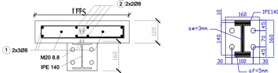
The test campaign realised at Stuttgart University was performed in strong collaboration with Liège University. The tested joint configuration (coming from the substructure designed and tested at Liège University) is presented in Figure 2. The tested joint configuration was designed so as to exhibit a ductile behaviour at collapse and with account of the M-N combined loading (Demonceau, 2008). The materials were ordered as follows: S355 steel for the profiles and the end-plates, ductile S450C steel for the rebars and C25/30 for the concrete.
500
Figure 2. Joint configuration tested at Stuttgart University
In total, five tests on this joint configuration have been performed. The objective of these tests is to derive the full M-N resistance interaction curve of the tested joints (in the tensile zone), as illustrated in Figure 3. They are distinguished by the loading sequences followed during the tests as described here after.
Three tests under hogging moments: one test with the joint first loaded under hogging bending moments until reaching the ultimate resistance in bending and secondly, after having slightly reduced the applied bending moment, loaded under tension loads until the collapse of the joint (TEST 1) and two tests with the joint, first, loaded under hogging bending moments with the loading stopped just before
reaching the ultimate resistance to bending and, secondly, loaded under tension loads until the collapse of the joint (TEST 2 & TEST 3).
Two tests under sagging moments: one test with the joint first loaded under sagging bending moments until reaching the ultimate resistance in bending and secondly, after having slightly reduced the applied bending moment, loaded under tension loads until the collapse of the joint (TEST 4) and one test with the joint, first, loaded under sagging bending moments with the loading stopped just before reaching the ultimate resistance to bending and, secondly, loaded under tension loads until the collapse of the joint (TEST 5).
Figure 3. M-N resistant resistance curve of the joint to be characterised through the performed tests
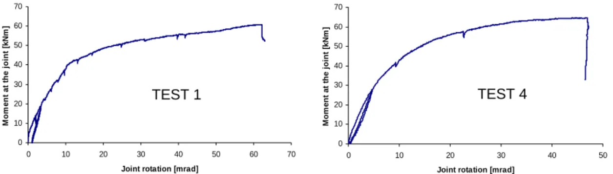
TEST 1 and TEST 4 were initially performed to characterise the behaviour of the tested joint under hogging and sagging moments. The obtained results are presented in Figure 4 where the bending moment vs. joint rotation obtained through these tests are presented. The M-N interaction curves obtained through the performed tests are presented in Figure 5. During the tests, the collapse of the rebars in tension was observed at point A of Figure 6 during TEST 1 and at point A’ during the other tests. After the collapse of the rebars, the tested joints can be considered as steel ones. It can be observed that, after the resistance loss, the remaining steel components are able to sustain additional tension loads. To pass from the pure bending moment loading to the maximum tensile load, only ductile components such as the end-plate and the column flange in bending or the rebars in tension were activated, as expected through the joint design.
All the observations made during the experimental tests are presented with more details in (Stuttgart University, 2008).
In the next section, the so-obtained experimental results are used to validate the developed analytical models.
0 10 20 30 40 50 60 70 0 10 20 30 40 50 60 70
Joint rotation [mrad]
M o m e nt a t t h e joint [ k N m ] 0 10 20 30 40 50 60 70 0 10 20 30 40 50
Joint rotation [mrad]
M o m e n t a t t h e jo in t [ k N m ]
Figure 5. Bending moment vs. joint rotation curves obtained through TEST 1 and 4 M N Mu A B Nu TEST 1 TEST 4
-75 -70 -65 -60 -55 -50 -45 -40 -35 -30 -25 -20 -15 -10 -5 0 5 10 15 20 25 30 35 40 45 50 55 60 65 70 0 40 80 120 160 200 240 280 320 360 400 440 480 520 560 600 640 680 N [kN] M [ k N ] TEST 1 TEST 2 TEST 3 TEST 4 TEST 5 HO GG IN G M O M E N T S S A G G IN G MO ME N T S TENSIO N A A'
Figure 6. M-N interaction curve obtained through the performed experimental tests
DEVELOPED DESIGN MODELS
Introduction
As previously mentioned, joints which are initially designed to transfer shear forces and hogging bending moments experience additional high tying forces after the loss of a column, as a result of the development of membrane forces in the beams located just above the damaged or destroyed column. Moreover a reversal of moments occurs in the joints located just above the damaged column, i.e. joints initially subjected to hogging bending moments are subjected to sagging ones.
In the present section, analytical models to predict the response of composite joints subjected to sagging moments and to combined bending moments and axial loads are described. More details about these methods are available in (Demonceau, 1998).
Design model for composite joints subjected to sagging bending moments
Within the Eurocodes, the analytical method recommended for the joint design is the “component method”. This method, as actually proposed, is not yet able to predict the behaviour of composite joints subjected to sagging bending moments. Indeed, no method is available to characterise one of the activated components under such loading: the concrete slab in compression.
In recent researches, methods to characterise this component in term of « resistance » are proposed. Their aim is to define a rectangular cross section of concrete participating to the joint resistance.
The procedure which is proposed in this section combined two methods proposed respectively by Fabio Ferrario (Ferrario, 2004) and by J.Y. Richard Liew (Liew et al, 2004). The combination of these two methods permits to reflect in a more appropriate way how the concrete resists to the applied load in the vicinity of the joint. Also, a formula for the characterisation of this component in term of “stiffness” is proposed. The so-defined analytical method is first described and then validated through comparison to the experimental test presented in the previous section.
In the PhD thesis of Fabio Ferrario (Ferrario, 2004), a formula is proposed to compute the width of the concrete beff,conn which has to be taken into account for the
joint component “concrete slab in compression”:
= + ≤
, 0,7
eff conn c c eff
b b h b
where bc is the width of the column profile flange, hc the height of the column profile
cross section and beff, the effective width of the concrete/composite slab to be
considered in the vicinity of the joint; bc represents the contribution of the concrete
directly in contact with the column flange while 0,7.hc the contribution of the
developed concrete rods in the “strut-and-tie” behaviour (see Figure 7).
In the article of J.Y. Richard Liew et al, the width of the concrete is taken as equal to the width of the column flange (beff,conn = bc) and the development of the concrete
rods in compression through the “strut-and-tie” model is neglected.
Figure 7. Plane view of the slab in the vicinity of the joint - development of concrete rods in compression under sagging moment
The definition of the width given in (Ferrario, 2004) is used in the developed procedure as this definition reflects in a more appropriate way the mechanism developing in the concrete slab according to the observations reported during experimental tests (Ferrario, 2004 and Demonceau, 2008).
Another difference between the two methods is linked to the definition of the height of concrete to be considered and, accordingly, to the position of the centre of compression within the joint. In (Ferrario, 2004), the centre of compression is assumed to be at mid-height of the concrete slab while in (Liew et al, 2004), the following procedure is given to compute the position of this point:
- the characterisation of the components in tension and eventually in shear is performed according to the rules recommended in the Eurocodes;
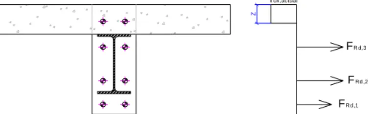
- then, the height of the concrete/composite slab contributing to the joint behaviour is computed by expressing the equilibrium of the load developing in the concrete/composite slab in compression with the components in tension or in shear and assuming a rectangular stress distribution in the concrete (equal to 0,85 fck/γc in a design). For instance, in the example illustrated in
Figure 8, the concrete height to be considered is equal to:
,1 ,2 ,3 , .(0,85. / ) Rd Rd Rd concrete eff conn ck c F F F z h b f γ + + = ≤
where hconcrete is the total height of the concrete slab (in case of a composite
- finally, the characterisation of the joint is performed assuming that the centre of compression is situated at the middle of the height of the contributing part of the concrete slab (z).
FRd,1
FRd,2
FRd,3
fck,actual
Z
Figure 8. Height of the concrete to be considered in the characterisation of the new component
It is the latter procedure which is considered in the proposed method as it reflects in a more appropriate way the actual behaviour of the joint according to the observations made during experimental tests (Demonceau, 2008).
So, the resistance of the component “concrete slab in compression” can be computed through the following formula:
FRd,CSC = beff,conn.z.(0,85.fck/γc)
The two previously mentioned references only deal with the characterisation of the component “concrete slab in compression” in term of resistance but no formulas are proposed to characterise the latter in term of stiffness; however, the latter is requested in order to be able to predict the initial stiffness of the joint (and to derive the moment-rotation curve).
If reference is made to (Weynand, 1999), a formula is proposed to predict the stiffness of a concrete block against a rigid plate. In the present case, the steel column encased in the concrete slab can be considered as a rigid plate; so, the formula proposed in (Weynand, 1999) can be extended to the present situation to compute the stiffness of the component under consideration:
, csc . . 1,275. c eff conn a E b z k E =
where EC is the secant Young modulus for the concrete, Ea, the elastic Young
modulus for the steel and kCSC, the stiffness of the component “concrete slab in
compression” to be considered in the component method.
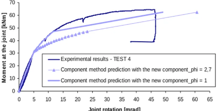
With the so-defined procedure for the characterisation of the component “concrete slab in compression”, the composite joint tested at Stuttgart University under sagging moments (i.e. TEST 4) has been characterised through the component method and the so-obtained prediction has been compared to the experimental results as presented in Figure 9.
Within the analytical computations, the actual material properties (without safety factors), determined through coupon tests for the steel materials and through cylinder compression tests for the concrete, are used.The resistant bending moment MRd and the initial stiffness Sj,ini are computed in full agreement with the component
method recommended in the Eurocodes while the ultimate moment Mu, the post-limit
stiffness Sj,post-limit and the rotation capacity φu are computed according to the method
agreement with the component method), as no methods are actually proposed in the codes to compute these properties.
In Figure 9, it can be observed that two analytical curves are reported; they are distinguished by the shape of the non-linear part of the curves. In fact, the non-linear part of the curves is computed according to the rule recommended in the Eurocodes and is a function of a shape coefficient called Ψ. The proposed value for joints with bolted end-plates is equal to 2.7. If this value is used, it can be observed in Figure 9 that the comparison with the experimental test result is not satisfactory. Indeed, the initial stiffness and the resistant and ultimate bending moments are in good agreement while the post-elastic stiffness is under-estimated. The observed difference is associated to the membranar forces within the joint components in bending (i.e. the column flange and the end-plate in bending) which develop when significant deformations are observed for the latter; this phenomenon is not yet included in the component method as actually proposed in the codes. If the shape coefficient is modified to take implicitly into account of this phenomenon (for instance, Ψ equal to 1), it can be observed that a very good agreement is obtained between the so-obtained analytical prediction and the experimental result. Further developments are requested on this topic; the latter are already initiated at Liège University. 0 10 20 30 40 50 60 70 0 5 10 15 20 25 30 35 40 45 50 55 60 65
Joint rotation [mrad]
M o m e n t a t t h e jo in t [k N m ]
Experimental results - TEST 4
Component method prediction with the new component_phi = 2,7 Component method prediction with the new component_phi = 1
Figure 9. Comparisons analytical predictions vs. experimental result (TEST 4) The proposed analytical model has also been validated through comparisons to other experimental results in (Demonceau, 2008).
Design model for composite joints subjected to combined bending moments and axial loads
The presence of axial loads in the beams has an influence on the rotational stiffness, the resistance moment and the rotation capacity of the joints. As the analytical method proposed in the Eurocodes, i.e. the component method, is dedicated to the characterisation of the joint subjected to bending moment only, the proposed field of application is limited to joints in which the axial force NEd acting in the joint remains
lower than 5 % of the axial design resistance of the connected beam cross section
Npl,Rd: , 0,05 Ed pl Rd N N ≤
This limitation is a fully arbitrary one and is not at all scientifically justified. It has also to be underline that this criterion only depends of the applied axial load NEd and of
the plastic resistance of the beam Npl,Rd which is quite surprising as what is
considered here is the influence of the applied axial load on the joint response.
If this criterion is not satisfied, the Eurocodes recommend to consider the resistant resistance diagram defined by the polygon linking the four points corresponding respectively to the hogging and sagging bending resistances in absence of axial force and to the tension and compression axial resistances in absence of bending. In a previous study (Cerfontaine, 2003), it was illustrated that the proposed method is quite questionable. So, in (Cerfontaine, 2003), an improved design procedure, based on the component method concept, has been developed to predict the response of steel joints subjected to combined axial loads and bending moments. In (Demonceau, 2008), the developed design procedure by F. Cerfontaine is extended to composite joints and validated through comparisons to the experimental test results obtained at Stuttgart University, as illustrated in Figure 10.
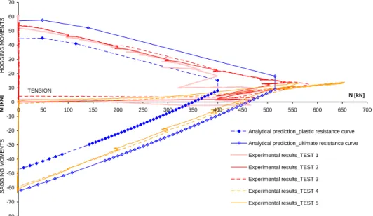
The computation details to obtain the analytical M-N resistance interaction curve are presented in (Demonceau, 2008). In Figure 10, it can be observed that two analytical curves are reported: one named “plastic resistance curve” which is computed with the elastic strengths of the materials and one named “ultimate resistance curve” which is computed with the ultimate strengths of the materials. In Figure 10, it can be seen that the computed analytical curves are in very good agreement with the experimental results. Indeed, the experimental curves are between the plastic and ultimate analytical resistant curves what is in line with the loading sequence followed during the tests.
Also, it is shown in Figure 10 that the maximum tensile load which can be supported by the joint is underestimated by the analytical procedure. This difference can be justified by the fact that the proposed analytical procedure does not take into account of the presence of membranar forces within the components “column flange in bending” and “end-plate in bending” associated to the big deformations of these components appearing when high tensile loads are applied to the joint. This phenomenon was already identified when investigating the behaviour the joint subjected to sagging bending moments.
-80 -70 -60 -50 -40 -30 -20 -10 0 10 20 30 40 50 60 70 0 50 100 150 200 250 300 350 400 450 500 550 600 650 700 N [kN] M [ k N ]
Analytical prediction_plastic resistance curve Analytical prediction_ultimate resistance curve Experimental results_TEST 1 Experimental results_TEST 2 Experimental results_TEST 3 Experimental results_TEST 4 Experimental results_TEST 5 HOGGING MOM E NT S S A GG IN G M O ME NTS TENSION
CONCLUSIONS
Within the present paper, experimental and analytical investigations conducted within a European project to investigate the behaviour of composite joints when significant membranar forces developed in a structure further to a column loss were presented. In particular, two analytical models dedicated to the prediction of the response of composite joints subjected to sagging moments and to combined bending moments and axial loads, situations not accurately covered by the actual codes, were briefly described and validated through comparisons with experimental results.
REFERENCES
BS 5950-1:2000 (2001), “Structural use of steelwork in building – Part 1: Code of practice for design – Rolled and welded sections”.
Cerfontaine, F. (2003), Study of the interaction between bending moment and axial force in bolted joints (in French). PhD thesis presented at Liège University.
Demonceau, J.-F. (2008), “Steel and composite building frames: sway response under conventional loading and development of membranar effects in beams further to an exceptional action”, PhD thesis presented at Liège University.
ENV 1991-2-7 (1998), “Eurocode 1: Basis of design and action on structures – Part 2-7 : Accidental actions due to impact and explosions”, final draft, June 1998.
Ferrario F., 2004, “Analysis and modelling of the seismic behaviour of high ductility steel-concrete composite structures”, PhD thesis presented at Trento University. Jaspart J.P. (1991), “Study of the semi-rigidity of beam-to-column joints and its influence on the resistance and stability of steel buildings”, PhD thesis, Liège University, in French.
Liew R.J.Y., Teo T.H. and Shanmugam N.E., 2004, “Composite joints subject to reversal of loading – Part 2: analytical assessments”, Journal of Constructional Steel Research, pp. 247-268.
prEN 1991-1-7 (2004), “Eurocode 1 – Action on structures – Part 1-7: General actions – Accidental actions”, final project team draft (stage 34), 9 July 2004.
Stuttgart University (2008), “Robust structures by joint ductility - Final report of the RFCS project N° RFS-CR-04046”, to be published.
UFC 4-023-03 (2005), “Unified Facilities Criteria (UFC) - Design of buildings to resist progressive collapse”, Department of Defence, USA. 25 January 2005.
Weynand K. (1999), “Column bases in steel building frames. COST C1 – Semi-rigid behaviour of civil engineering structural connections”, Luxembourg.