i
Faculté de génie
Département de génie civil et de génie du bâtiment
FLEXURAL BEHAVIOUR OF POSTTENSIONED
CONCRETE-FILLED FIBER-REINFORCED
POLYMER RECTANGULAR TUBE BEAMS:
EXPERIMENTAL AND ANALYTICAL
INVESTIGATIONS
COMPORTEMENT EN FLEXION DE POUTRES
TUBULAIRES RECTANGULAIRES (EN POLYMERE
RENFORCE DE FIBRES) EN BETON ARME ET
POST-CONTRAINTES : ÉTUDES EXPERIMENTALE ET
ANALYTIQUE
Thèse de doctorat Spécialité: génie civil
Asmaa Abd El Daim Ibrahim Ahmed
A dissertation submitted in partial fulfillmentof the requirements for the degree of Doctor of Philosophy
(Civil Engineering)
Jury: Prof. RadhouaneMASMOUDI, Université de Sherbrooke (Directeur de recherche)
Prof. Sébastien LANGLOIS, Université de Sherbrooke (Rapporteur et Examinateur) Prof. Mohamed LACHEMI, Ryerson University (Examinateur)
Prof. Khaled SENNAH, Ryerson University (Examinateur) Prof. M.-Iqbal KHAN, King Saud University (Examinateur)
ABSTRACT
Corrosion damage is recognized as a crucial factor for existing concrete bridge girders and corresponding consequences are significant. A promising solution has recently been proposed using posttensioned (PT) concrete-filled fiber-reinforced polymer (FRP) tubes (CFFTs) to effectively improve the performance of new concrete structures. Despite this system demonstrated benefits in terms of improving structural behavior, there still is a lack of research, including the functional reliability of posttensioned rectangular CFFT members. Moreover, there are no code provisions for the flexural design of PT rectangular CFFT members. To achieve their broad-based implementation in civil infrastructures, understanding of their flexural behavior is essential. This study presents the results of a comprehensive test program that was aimed at investigating the flexural behavior of rectangular CFFT beams posttensioned with unbonded steel tendons to address the knowledge research gaps in this field. The tests intend to simulate a number of design parameters, which are mainly governed by flexural loading. Fifteen full-size beams with internal steel bars were tested, including thirteen PT CFFTs and two PT concrete beams along with one non-PT CFFT from the literature for comparison. The investigated parameters are i) GFRP tube thickness ranged from 6.0 mm to 12.3 mm; ii) Tube fiber structural laminate; iii) Tube confinement versus steel stirrups; iv) Number of prestressing tendons and level of prestressing; v) Concrete compressive strength [(normal and high strength concrete (NSC and HSC)]; vi) Total reinforcement index; vii) Attaching a thin Carbon FRP-laminated embedded in tension flange and its ratio; and viii) Loading scheme (static and cyclic). Moreover, an analytical study was conducted to develop a model to predict the ultimate strength of prestressed CFFT members. The model is based on strain compatibility and force equilibrium, which account for the material constitutive relationships for FRP tube laminates, steel strands, and non-linearity of concrete. The accuracy of the proposed model is also verified against the experimental results. Finally, a new design equation, as an extension to AASHTO (2012) equation, is also established based on a regression analysis of the test results to predict the ultimate flexural capacity of the tested beams, which significantly impacts the design practice of such members. The experimental results demonstrated the feasibility and construction of rectangular CFFTs posttensioned with steel tendons. The test results indicated that rectangular CFFT beams prestressed with unbonded steel strands could effectively replace conventional members made from traditional materials or identical rectangular CFFT without prestressing, in terms of similar or better structural performance. The flexural behavior of the tested PT CFFT beams is highly depended on the FRP tube confinement, laminate, thickness, and attaching a thin Carbon FRP-laminated embedded in tension flange, and to a much less extent, on the magnitude of the prestress level, the number of strands, concrete strength, and loading scheme. Furthermore, it was found that neglecting concrete confinement in the proposed model highly underestimates the flexural strength. The promising results of this study can provide the impetus for constructing a new sustainable and high-performance hybrid structural rectangular PT CFFT elements.
Keywords: Bridge; Posttensioned; CFFT; FRP; Flexural Loading; Confinement; Cyclic;
iii
RÉSUMÉ
Les dommages des infrastructures en béton dus à la corrosion représentent un facteur crucial pour les poutres de pont en béton et les conséquences associées à ces dommages sont très importantes. Malgré les avantages évidents de ce système en termes d'amélioration du comportement structural et de durabilité, il y a encore un grand manque de données expérimentales et de modélisation, y compris la faisabilité fonctionnelle des éléments tubes en polymère renforcé de fibres (PRF) et remplis de béton (TPRB) rectangulaires PC. De plus, il n'y a pas de normes pour la conception en flexion de ces éléments. Pour parvenir à la mise à l’échelle et à l’introduction de ces éléments TPRB dans les infrastructures civiles, la compréhension et la modélisation de leur comportement en flexion est indispensable.
Étant la toute première étude expérimentale sur le sujet, cette étude présente les résultats d'un programme expérimental visant à étudier le comportement en flexion des poutres TPRB rectangulaires PC (avec des tendons en acier post-tensionnés) pour combler la lacune de recherche susmentionnée. Le programme expérimental vise à simuler un certain nombre de paramètres de conception des TPRB-PC. Treize poutres (à échelle réelle, incorporant des barres d’armature en acier) dont douze TPRB rectangulaires PC, deux poutres en béton armé conventionnel et PC et une poutre TPRB sans post-tension (pour comparaison) ont été testées. Les principaux paramètres étudiés sont : (i) l'épaisseur du tube GFRP variant de 6,0 mm à 12,3 mm; (ii) l’orientation et l’empilement des couches des fibres dans les tubes ; (iii) le confinement par des tubes par rapport aux étriers en acier dans les poutres conventionnelles; (iv) le nombre de tendons et le niveau de précontrainte ; (v) la résistance à la compression du béton [béton normal (BO) et béton à haute résistance (BHP)] ; (vi) l'indice de renforcement total; (vii) l’effet de l’intégration d’une fine lamelle de carbone en PRF dans une la zone tendue du tube en PRF; et (viii) type de chargement (statique et cyclique). De plus, une étude analytique a été menée afin de développer un modèle permettant de prédire la force ultime des éléments TPRB-PC. Le modèle est basé sur la compatibilité des contraintes et l'équilibre des forces, qui tiennent compte des relations constitutives des matériaux (laminés de tubes FRP,
tondons d'acier, et la non-linéarité du béton). La précision du modèle proposé est également vérifiée par rapport aux résultats expérimentaux. Enfin, une nouvelle équation de conception, en tant qu'extension de l'équation de l'AASHTO (2012), est également établie (sur la base d'une analyse de régression des résultats expérimentaux) pour prédire la capacité de flexion ultime des poutres TPRB-PC testées, ce qui pourra avoir un impact significatif sur la pratique de conception des éléments TPRB-PC.
Les résultats expérimentaux ont démontré la faisabilité des éléments TPRB PC avec des tendons d'acier. Les résultats ont ainsi indiqué que les poutres TPRB PC peuvent effectivement remplacer les éléments conventionnels fabriqués à partir de matériaux traditionnels ainsi que les TPRB sans pré ou post-tension, tout en démontrant des performances structurales nettement supérieures. Le comportement en flexion des poutres TPRB -PC testées dépend fortement du confinement des tubes en PRF, de la séquence d’enroulement et de l’orientation des fibres, de l'épaisseur et de l’intégration d'une mince couche de laminé en PRF de carbone et, dans une moindre mesure, de l'ampleur du niveau de post-tension, du nombre de torons, de la résistance du béton et du type de chargement. En outre, il a été constaté que le fait de négliger l’effet de confinement du béton dans le modèle proposé sous-estime fortement la résistance en flexion. Les résultats prometteurs de cette étude peuvent promouvoir la construction des structures hybrides (faites à partie des TPRB rectangulaires PC) plus durables et plus performantes.
Mots clés : Pont; post-tension; polymères renforcés de fibre (PRF); capacité de flexion;
v
ACKNOWLEDGEMENT
Praise be to Allah Almighty and Peace be upon His Prophet Muhammad.
The author would like to express her profound gratitude and appreciation to her supervisor, Prof. Radhouane MASMOUDI, not only for his support, strong believe in me, and patience throughout the course of this study but also for giving an opportunity to conduct this research. I do feel that I have been extremely fortunate to have Professor MASMOUDI as a supervisor since the winter of 2015 when I started my master’s degree program.
The author would like to express her faithful appreciation to Dr. Mohamed HASSAN, for his technical support and guidance throughout this research program. I cannot stress enough the so-much vital moral support I received from Dr. HASSAN, and it is owing to his support that I was able to complete my study successfully.
The author would like to thank the jury members for reviewing the author’s Ph.D. dissertation and deeply appreciate their valuable comments and appreciation on this work.
Sincere thanks go to Prof. Jean Proulx, the head of the Department of Civil and Building Engineering, for his kind support during the author’s experimental testing.
The assistance of the technical staff of the Structural and Materials Laboratory in the Department of Civil and Building Engineering at the Université de Sherbrooke, in particular Mr. Claude Aubé, Mr. Sébastien Rioux, Mr. Eric Belisle, Mr. Jeason Desmarais, and Mr. Steven Mac Eachern is also greatly appreciated.
The financial support received from the Fonds de recherche du Québec – Nature et Technologies – (FRQNT) (Doctoral Scholarship), the Natural Sciences and Engineering Research Council of Canada (NSERC) and contribution of the Canadian Foundation for Innovation (CFI) for the infrastructure is deeply appreciated.
The author would like to express her deepest appreciation and thanks to her parents, sisters and mother in law for their endless love, support, encouragement, duas, and prayers. The spiritual support of all of them cannot be praised enough. The author is indebted to her father, who sacrificed his life for her family when she was growing up. I have a great believe that he is the real reason of my accomplishments in my life.
Words stand helpless and cannot express my deepest love and appreciation to my husband (Mohamed) for his faithful encouragement, for his endless support and his prominent role in helping me to achieve one of the greatest accomplishments in my life; his selflessness will always be remembered. I cannot present this work without expressing my love to my sweetie son (Omar) and my lovely daughter (Aseel), who enlightened my life with their smile; to them this thesis is dedicated.
Asmaa Abdeldaim Ahmed
2020
Dedication
To the memory of my father “Abd el daim” To my mother and sisters
To the memory of my Mother in law
To my dear husband “Mohamed” and my sweetie kids “Omar” and “Aseel”
vii
TABLE OF CONTENTS
ABSTRACT ... II
RÉSUMÉ ... III
ACKNOWLEDGEMENT ... V
TABLE OF CONTENTS ... VII
LIST OF TABLES ... XIII
LIST OF FIGURES ... XIV
LIST OF SYMBOLS ... XIX
CHAPTER 1
INTRODUCTION ... 1
1.1 Context and Problem Definition ... 1
1.2 Research Significance ... 2
1.3 Research Originality and Objectives ... 3
1.4 Methodology ... 4
1.5 Organization of the Dissertation ... 5
CHAPTER 2
LITERATURE REVIEW ... 7
2.1 General ... 7
2.2 FRP Composite Materials ... 8
2.3 Manufacturing Processes of FRP Composites ... 9
2.3.1 Pultrusion Process... 10
2.3.2 Resin Transfer Molding (RTM) Process ... 10
2.3.3 Vacuum Assisted Resin Transfer Molding (VARTM) Process ... 11
2.3.4 Compression Molding Process ... 12
2.3.5 Filament Winding Process ... 12
2.4.1 Pretensioning Technology ... 15 2.4.2 Posttensioning Technology ... 16 2.4.3 Prestress Losses ... 17 2.4.3.1 Losses at Jacking ... 17 2.4.3.2 Losses at Transfer... 18 2.4.3.3 Time-dependent Losses ... 18
2.5 Flexural Behaviour of Prestressed CFFTs ... 19
2.6 Significant Parameters Affecting the Behaviour of Reinforced/Prestressed CFFTs Subjected to Bending or Combined Bending and Axial Loads ... 26
2.6.1 Effect of Concrete Strength ... 26
2.6.2 Effect of Internal Reinforcement Type (Steel or FRP bars) ... 27
2.6.3 Effect of Tube Thickness ... 28
2.6.4 Effect of Tube Laminate Structure (Fibers Orientation) ... 32
2.6.5 Effect of Bond ... 35
2.6.6 Effect of Geometry and Cross-Section Configuration ... 38
2.6.7 Effect of Central Hole ... 40
2.7 Summary ... 48
CHAPTER 3
EXPERIMENTAL PROGRAM ... 50
3.1 General ... 50
3.2 Material Properties ... 50
3.2.1 Concrete ... 51
3.2.2 Deformed steel bars ... 52
3.2.3 Steel strands ... 53
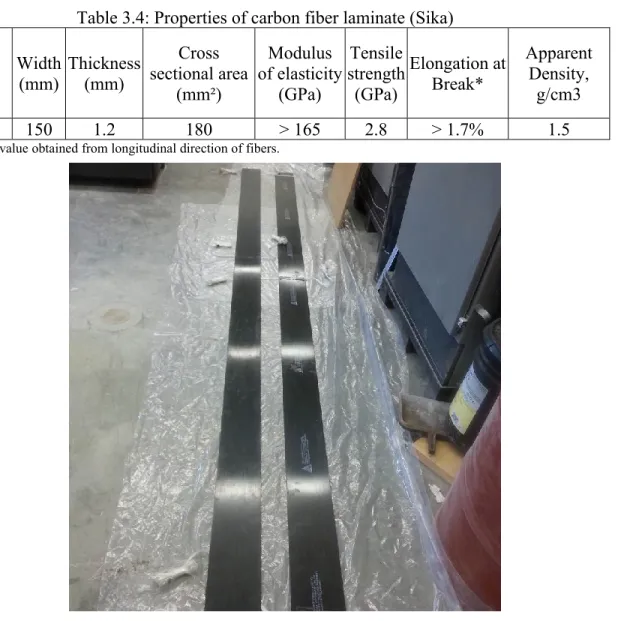
3.2.4 Carbon-FRP (CFRP) strips ... 54
3.2.5 GFRP filament-winding tubes and fabrication ... 55
3.3 Test Parameters and Specimens’ Details ... 65
3.4 Fabrication of the Test Specimens and Casting ... 66
3.5 Prestressing Procedure of Post-tensioning ... 73
ix
CHAPTER 4
EFFECT OF CONCRETE STRENGTH AND TUBES
THICKNESS ON THE FLEXURAL BEHAVIOR OF PRESTRESSED
RECTANGULAR CONCRETE FILLED FRP TUBE (CFFT) BEAMS ... 80
4.1 Abstract ... 81 4.2 Introduction ... 82 4.3 Research Significance ... 84 4.4 Experimental Work ... 84 4.4.1 Material properties ... 84 4.4.2 Test matrix ... 87
4.4.3 Preparation of test specimens ... 88
4.4.4 Test setup and instrumentation ... 89
4.4.5 Prestressing procedure ... 90 4.5 Test Results ... 93 4.5.1 Mode of failure ... 93 4.5.2 Load–deflection responses ... 95 4.5.3 Load-strain responses ... 95 4.5.4 Load–slip relationships ... 99 4.6 Discussion ... 100
4.6.1 Effect of confinement using GFRP tube ... 100
4.6.2 Effect of concrete compressive strength ... 101
4.6.3 Effect of GFRP tube thickness ... 102
4.6.4 Ductility and Energy Absorption ... 103
4.7 Analytical Investigation ... 105
4.7.1 Analytical model ... 105
4.7.2 Simplified design formula ... 107
4.7.3 Ultimate moment predictions ... 108
4.8 Conclusions ... 108
CHAPTER 5
FLEXURAL PERFORMANCE OF UNBONDED
POST-TENSIONED RECTANGULAR CONCRETE-FILLED FRP TUBE
BEAMS
... 111
5.1 Abstract ... 112
5.2 Introduction ... 112
5.3 Research Significance ... 115
5.4 Experimental Program ... 115
5.4.1 Specimens configuration and parameters ... 115
5.4.2 Material properties ... 117
5.4.1 Specimens preparation ... 119
5.4.2 Instrumentation and test setup ... 120
5.4.3 Prestressing Procedure ... 123
5.5 Test results and Observation ... 126
5.5.1 General Behavior and Mode of Failure ... 126
5.5.2 Load–Deflection Characteristics ... 127
5.5.3 Load-Strain Responses ... 129
5.5.4 Progression of Neutral Axis Depth ... 131
5.5.5 Load–Slip Relationships ... 132
5.6 Discussion ... 133
5.6.1 Effect of Prestressed Reinforcement ... 133
5.6.2 Effect of GFRP Tube ... 134
5.6.3 Effect of GFRP Tube Wall Thickness ... 135
5.6.4 Effect of Prestressing Level ... 136
5.6.5 Effect of Number of Strands ... 137
5.6.6 Ductility and Energy Absorption ... 137
5.7 Evaluation of Ultimate Flexural Strength ... 138
5.7.1 Analytical Model ... 138
5.7.2 Simplified Design Approach ... 141
5.7.3 Comparison of Analytical Experimental Results ... 141
5.8 Conclusions ... 142
CHAPTER 6
FLEXURAL
BEHAVIOR
OF
POST-TENSIONED
NORMAL AND HIGH STRENGTH CONCRETE FILLED FRP TUBES
(CFFTS) ... 144
xi
6.1 Abstract ... 145
6.2 Introduction ... 145
6.3 Research Significance ... 148
6.4 Experimental Program ... 148
6.4.1 Test matrix and parameters ... 148
6.4.2 Material properties ... 149
6.4.3 Fabrication of test specimens ... 155
6.4.4 Instrumentation ... 155
6.4.5 Testing ... 156
6.4.6 Prestressing procedure ... 157
6.5 Test results and observations ... 158
6.5.1 General Behaviour and Mode of Failure ... 158
6.5.2 Load–Deflection Relationships ... 161
6.5.3 Load-Strain Relationships ... 163
6.5.4 Load–Slip Relationships ... 166
6.5.5 Ductility and Deformability ... 166
6.5.6 Energy Absorption ... 169
6.6 Discussion ... 169
6.6.1 Effect of Prestressed Reinforcement ... 169
6.6.2 Effect of GFRP tube ... 170
6.6.3 Effect of GFRP Tube Thickness ... 170
6.6.4 Effect of Concrete Compressive Strength ... 171
6.6.5 Effect of Load Schemes ... 172
6.6.6 Effect of Number of Tendons ... 173
6.7 Ultimate Flexural Capacity Predictions ... 174
6.7.1 Comparison of Analytical Experimental Results ... 174
6.1 Conclusions ... 175
CHAPTER 7
EFFECT OF TUBE LAMINATE AND TENSIONED
CARBON-FRP STRIPS ON FLEXURAL RESPONSE OF PRESTRESSED
RECTANGULAR CFFT BEAMS ... 177
7.1 Abstract ... 178 7.2 Introduction ... 178 7.3 Research Significance ... 181 7.4 Experimental Program ... 181 7.4.1 Material characteristics ... 181 7.4.2 Test matrix ... 184 7.4.3 Specimens’ Preparation ... 186 7.4.4 Instrumentation ... 186
7.4.5 Experimental Setup and Prestressing Procedure ... 186
7.5 Test Results and Observation ... 189
7.5.1 Failure Mode ... 189
7.5.2 Load–deformation Relationships ... 191
7.5.3 Load-strain Relationships ... 193
7.5.4 Progression of Neutral Axis Depth ... 195
7.5.5 Load–slip Relationships ... 196
7.6 Discussion ... 197
7.6.1 Effect of Fiber Structural Laminate ... 197
7.6.2 Effect of total reinforcement index ratios ... 197
7.6.3 Effect of carbon FRP-laminated in tension flange and its ratio ... 198
7.7 Ductility Index and Energy Absorption ... 199
7.8 Theoretical Study ... 201
7.8.1 Comparison of analytical experimental results ... 203
7.9 Conclusions ... 204
CHAPTER 8
SUMMARY AND CONCLUSIONS ... 206
8.1 Summary ... 206
8.2 Conclusions ... 207
8.3 Conclusions en Français ... 209
8.4 Recommendations for Future Work ... 211
xiii
LIST OF TABLES
Table 3.1: Final mixture designs ... 51
Table 3.2: Mechanical properties of steel reinforcing bars (Grade 60) ... 53
Table 3.3: Properties of prestressing strands ... 54
Table 3.4: Properties of carbon fiber laminate (Sika) ... 55
Table 3.5: Mechanical properties of glass fibers ... 56
Table 3.6: Mechanical properties of resin ... 56
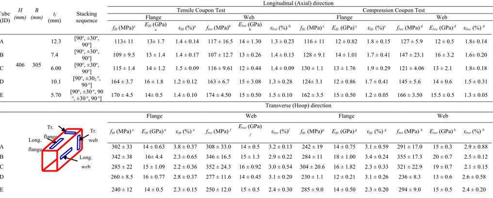
Table 3.7: Mechanical properties of GFRP tubes in longitudinal and transverse directions .... 60
Table 3.8: Test specimen’s details ... 68
Table 4.1: Mechanical properties of GFRP tubes in longitudinal and transverse directions .... 85
Table 4.2: Details of test specimens ... 86
Table 4.3: Mechanical properties of steel strands and reinforcing bars ... 87
Table 4.4: Summary of the test results, ductility, energy absorption, and flexural ultimate moment capacity predictions ... 98
Table 5.1: Details of test specimens ... 117
Table 5.2: Mechanical properties of steel strands and reinforcing bars ... 119
Table 5.3: Mechanical properties of GFRP tubes in longitudinal and transverse directions .. 122
Table 5.4: Summary of the test results and ultimate flexural capacity predictions ... 125
Table 6.1: Details of test specimens ... 151
Table 6.2 : Mechanical properties of GFRP tubes in axial and hoop directions ... 154
Table 6.3 : Mechanical properties of steel strands and reinforcing bars ... 154
Table 6.4: Summary of the test results ... 164
Table 6.5: Ductility, deformability, and energy absorption ... 169
Table 6.6: Ultimate flexural capacity predictions ... 175
Table 7.1: Details of test specimens ... 182
Table 7.2: Mechanical properties of steel strands and reinforcing bars ... 182
Table 7.3: Mechanical properties of GFRP tubes in longitudinal and transverse directions .. 184
LIST OF FIGURES
Figure 2.1: Typical stress-strain relationships of different FRPs compared to steel bars
(Zhishen et al. 2012) ... 9
Figure 2.2: Schematic of pultrusion process [http://mdacomposites.org] ... 10
Figure 2.3: Schematic of RTM process [http://mdacomposites.org] ... 11
Figure 2.4: Schematic of VARTM process [http://mdacomposites.org] ... 12
Figure 2.5: Schematic of filament winding machine [http://mdacomposites.org] ... 14
Figure 2.6: Stages of pretensioning, (a) Applying tension to tendons, (b) Casting of concrete, (c) Transferring of prestress. ... 15
Figure 2.7: Post-tensioning of the member ... 16
Figure 2.8: Nominal load versus deflection behavior of GFRP tube compared with steel spiral [Mandal and Fam 2006] ... 20
Figure 2.9: Prestressed and regular CFFTs moment-curvature comparison (Mandel and Fam 2006) ... 21
Figure 2.10: CFFTs for precast modular bridge pier system [Zhu et al. 2003] ... 23
Figure 2.11: Behaviour of partially prestressed CFFTs, based on analytical modeling ... 25
Figure 2.12: Effect of rebar type and ratio for reinforced CFFT beams [Cole and Fam 2006] 28 Figure 2.13: Moment-deflection responses [Abouzad and Masmoudi 2016] ... 29
Figure 2.14 : Large beam-column tests on CFFTs [Mirmiran et al. 2000] ... 31
Figure 2.15: Normalized load-deflection envelopes of CFFTs [Shao 2003] ... 34
Figure 2.16 : Load-deflection response and failure modes of B3 and B4 [Fam and Rizkalla 2002] ... 34
Figure 2.17: Beam test results of Belzer et al. (2013) ... 37
Figure 2.18: Interaction diagrams of CFFTs vs. RC columns [Mirmiran et al. 1999] ... 38
Figure 2.19: Comparison of envelope curves of RC section and CFFTs of CFRP tubes ... 39
Figure 2.20: Configuration of CFFT beams [Abouzad and Masmoudi (2015)]. ... 41
Figure 2.21: Moment–deflection responses of the tested beams [(Abouzad and Masmoudi (2015)]. ... 41
xv
Figure 2.23: Load–mid-span deflection responses of DSTBs [(Idris and Ozbakkaloglu (2014)].
... 43
Figure 2.24: Determination of optimal concrete filling length ratio for partially filled CFFTs 44 Figure 2.25: Load-deflection behaviour of partially filled CFFTs (Mitchell, 2008) ... 44
Figure 2.26: Beam test results of [Fam et al. (2005)]. ... 46
Figure 2.27: Load-deflection behavior for different CFFT beam configurations ... 47
Figure 2.28: Moment-curvature response and failure modes of B1 and B2 [Fam and Rizkalla 2002] ... 48
Figure 3.1: Ready concrete mixer and pump, slump cone after adding super plasticizers, and typical axial stress-strain relationships for concrete cylinders ... 52
Figure 3.2: Deformed steel bars 15M and 10M used in this investigation ... 53
Figure 3.3: Seven-wire strand type 0.6” (15.2 mm)- Grade 270 used in this investigation ... 54
Figure 3.4: Sika CarboDur type S1512 ... 55
Figure 3.5: Filament winding machine at U de S ... 56
Figure 3.6: E-glass fiber roving. ... 57
Figure 3.7: Fibers installment in filament winding process: (a) Fibers roving on creels; (b) ... 58
Figure 3.8: Computer system and program controlling the mandrel speed ... 59
Figure 3.9: Fiber laminates structure patterns ... 61
Figure 3.10: Curing process of FRP tubes ... 62
Figure 3.11: Assembling the rigid frame and removing the mandrel in a horizontal position .. 62
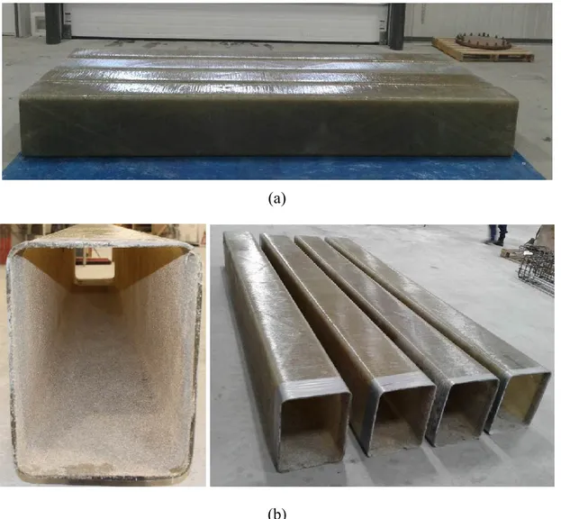
Figure 3.12: a) Fabricated GFRP tubes at the desired length of the beam prototypes. b) Sand coating the inner surface of the tubes. ... 63
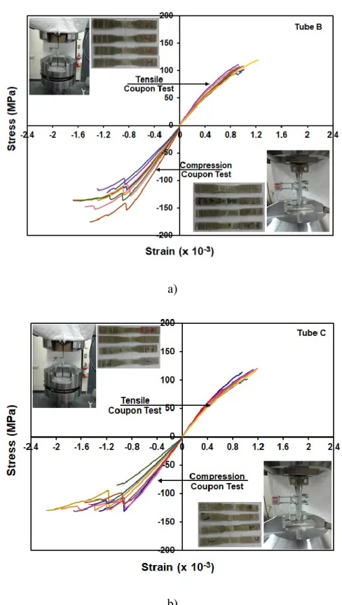
Figure 3.13: Axial stress-strain responses obtained from coupon tests for tube B & C. ... 64
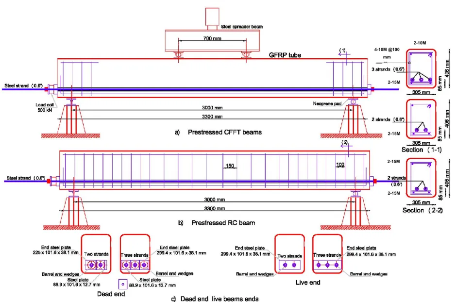
Figure 3.14: PT CFFT and PT concrete beams geometry and reinforcement details ... 69
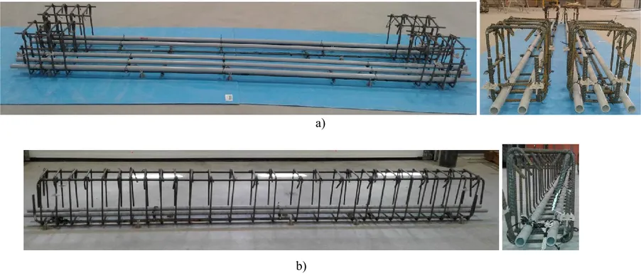
Figure 3.15: Steel reinforcement cages: a) PT CFFTs with 2 and 3 strands; b) PT control beams ... 70
Figure 3.16: Prestressed RC and CFFRTs prior casting ... 71
Figure 3.17: Concrete Casting for PT control and PT CFFT beams ... 72
Figure 3.18: PT control and PT CFFT beams through curing ... 73
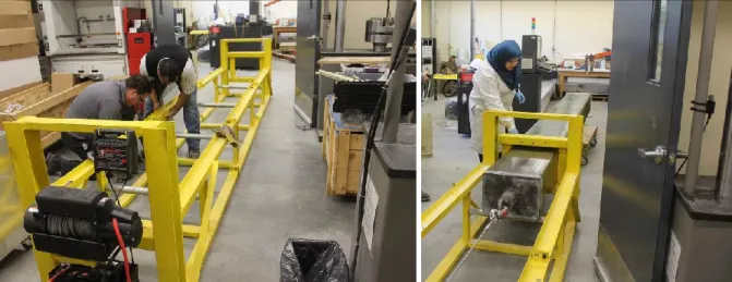
Figure 3.19: Post-tensioning frame setup and loading application ... 74
Figure 3.21: Displacement routine loading schematic ... 77
Figure 3.22: Instrumentation for the deformed steel bars and strands ... 77
Figure 3.23 : a) Instrumentation schematic; b) positions of different sensors ... 78
Figure 3.24: The data acquisition system ... 79
Figure 4.1: Axial stress-strain responses obtained from coupon tests; and fabricated tubes using filament-winding manufacturing process ... 86
Figure 4.2: Prestressed CFFT and RC beams geometry and reinforcement details ... 89
Figure 4.3: Prestressed CFFT and RC beam specimens’ fabrication ... 89
Figure 4.4: a) Test setup; b) Posttensioning frame setup and loading application ... 91
Figure 4.5: a) Instrumentation schematic; b) positions of different sensors ... 92
Figure 4.6: Mode of failure of the tested beams and concrete cracks patterns after removing the GFRP tube ... 94
Figure 4.7: Load-deflection responses of the full-scale tested specimens ... 97
Figure 4.8: Load–strain behaviors: a) axial strains of FRP tube or concrete surface; b) hoop strains of FRP tube, and c) steel strands strains ... 99
Figure 4.9: Load–slip relationships measured between FRP tube and concrete ... 100
Figure 4.10: Variation of the neutral axis location as a function of applied load ... 101
Figure 4.11: Axial versus hoop strain behavior ... 102
Figure 4.12: a) Ductility factor definition (Grace et al. 1998); b) Total energy absorption of the test specimens ... 104
Figure 4.13: Stress–strain models for partially confined and unconfined concrete and steel strands. ... 107
Figure 4.14: Proposed analytical model stress and strain distribution ... 107
Figure 5.1: Beams’ geometry and reinforcement details: a) PCCFT; b) PRC; and c) Dead and live ends. ... 118
Figure 5.2: a) Fibers roving; b) Filament winding manufacturing; and c) casting setup ... 121
Figure 5.3: Instrumentation (SPs and strain gauges’ layout) ... 121
Figure 5.4: Test setup ... 123
Figure 5.5: Post-tensioning frame setup and loading application ... 124
Figure 5.6: Mode of failure of the tested beams and concrete cracks patterns after removing the GFRP tube ... 127
xvii
Figure 5.7: Comparisons between load-deflection responses of the tested beams with different
investigated parameters ... 129
Figure 5.8: Load–strain behaviors of FRP tube or concrete surface (for specimen P1-S-2) and steel strands ... 131
Figure 5.9: Variation of the neutral axis location as a function of applied load ... 132
Figure 5.10: Load–slip relationships measured between FRP tube and concrete ... 133
Figure 5.11: Axial versus hoop strain behavior ... 136
Figure 5.12: Stress–strain models for partially confined and unconfined concrete and steel strands. ... 140
Figure 5.13: Proposed analytical model stress and strain distribution ... 141
Figure 6.1: Beams’ geometry and reinforcement details: a) PT CCFT; b) PT concrete beam; and c) Dead and live ends ... 152
Figure 6.2: a) Fabricated tubes using filament-winding manufacturing process; b) PT CFFTs casting and curing ... 153
Figure 6.3: Instrumentation (SPs and strain gauges’ layout) ... 156
Figure 6.4: Test setup and displacement routine loading schematic ... 157
Figure 6.5: Posttensioning frame setup for two and three strands and loading application ... 158
Figure 6.6: Mode of failure of the tested beams ... 159
Figure 6.7: Concrete cracks patterns after removing the GFRP tube ... 160
Figure 6.8: Comparisons between load-deflection responses of the tested beams with different investigated parameters ... 162
Figure 6.9: Load–strain relationships of FRP tube or concrete surface (for specimens P1-S-2-N and P1-S-2-H) and steel strands ... 165
Figure 6.10: Load–slip curves measured between FRP tube and concrete ... 166
Figure 6.11: Definitions of absorbed energies ... 168
Figure 6.12: Axial versus hoop strain behavior ... 171
Figure 6.13: a) Measured PT force histories for the test specimens under monotonic and cyclic loading; b) residual posttensioning force ratio ... 173
Figure 7.1: Behavior of GFRP coupons in axial direction and coupons test setup ... 183
Figure 7.2: Beams’ geometry and reinforcement details ... 185
Figure 7.4: Experimental setup ... 188
Figure 7.5: Posttensioning frame setup and loading application ... 188
Figure 7.6: Mode of failure of the tested beams and Concrete cracks patterns after removing the GFRP tube ... 190
Figure 7.7: Comparisons between load-deformation responses of the tested beams with different investigated parameters ... 191
Figure 7.8: Load–strain responses of FRP tube and steel strands ... 194
Figure 7.9: Variation of the neutral axis location as a function of applied load ... 195
Figure 7.10: Load–slip relationships measured between FRP tube and concrete ... 196
Figure 7.11: Axial versus hoop strain behavior ... 198
Figure 7.12: Definitions of absorbed energies (Grace et al. 1998) ... 201
Figure 7.13: Stress–strain models: a) Partially confined and unconfined concrete; b) Steel strands. ... 202
Figure 7.14: Proposed analytical model stress and strain distribution ... 203
xix
LIST OF SYMBOLS
SI units are used throughout the study presented herein. Unless otherwise stated, the symbols most frequently used have the following meanings:
Symbol Definition
Abar cross-sectional area of steel bar, (mm2)
Ast cross-sectional area of steel strand, (mm2)
CFFT concrete filled FRP tube
b cross-section width, (mm) d effective depth, (mm) c neutral axis depth, (mm)
Elft elastic modulus of tube tension flange in axial direction, (GPa)
Elfc elastic modulus of tube compression flange in axial direction, (GPa)
Elwc elastic modulus of tube compression web in axial direction, (GPa)
FRP fiber reinforced polymer
fc’ unconfined concrete compressive strength, (MPa)
ffu tensile strength of the tube in the longitudinal direction, (MPa) fy yield tensile stress of the steel rebars, (MPa)
fsu ultimate tensile stress of the steel strands, (MPa)
flft tensile stress of tube flange in axial direction, (MPa) flfc compression stress of tube flange in axial direction, (MPa) flwc compression stress of tube web in axial direction, (MPa) h member total height, (mm)
Mcr moment at the first crack, (kN.m)
Mu ultimate moment capacity of prestressed CFFT beams, (kN.m) Pcr load at the first crack, (kN)
Py yield load, (kN) Pu ultimate load, (kN) PT posttensioning PC prestressed Concrete
NSC normal strength concrete
HSC high strength concrete tf thickness of FRP tube, (mm)
ωt total reinforcement index
ωf reinforcement index of FRP tube
ωbar reinforcement index of steel rebars
ωst reinforcement index of steel tendons
ρf FRP tube reinforcement ratio, (=Atube/Aconcrete)
ρbar steel rebars reinforcement ratio, (=Abar/bdbar)
ρst steel tendons reinforcement ratio, (Ast/bdst)
Δcr deflection at cracking
Δy deflection at yielding Δu deflection at ultimate
εc ultimate strain in compression surface
εt ultimate strain in tension surface
εlft tensile strain of tube flange in axial direction
εlwt tensile strain of tube web in axial direction
εlfc compression strain of tube flange in axial direction
εlwc compression strain of tube web in axial direction
λ ductility factor
μp energy ratio up to peak load
CHAPTER 1
INTRODUCTION
1.1 Context and Problem Definition
The deterioration in concrete structures due to corrosion of steel reinforcements is one of the major challenges facing the construction industry. Currently, many bridges in the United States, Canada, and Europe are approaching the end of their design life, and some bridges are showing major signs of structural damage such as corrosion of steel reinforcements and large cracks. This is due to their high level of exposure to environmental factors. According to the 2017 Report Card for America’s infrastructure, nearly 1/11 of the 614,387 bridges in the National Bridge Inventory were classified as structurally deficient (ASCE 2017). Of this total, more than 108,000 were prestressed concrete (PC) bridges (NACE International 2012). Therefore, a substantial number of bridges are in need of replacement or structural strengthening to extend their service life.
Fiber-reinforced polymer (FRP) has been identified as a potential solution to the dominant deterioration problems of the aging infrastructure. One promising solution to mitigate the corrosion problem in the new bridges is to utilize the concept of concrete filled FRP tubes (CFFTs). The FRP tube provides the stay-in-place formwork, protective jacket, and shear and flexural reinforcements. The innovative concept has already been successfully used as bridge piles and pier columns (Mirmiran and Shahawy 2003; Pando et al. 2003) and bridge girders (Zhao et al. 2000). The latter application used in the Kings Storm Water Channel Bridge girders in Riverside County, California and in the I-5 Gilman Bridge across the University of California, San Diego campus in La Jolla, California (Seible et al. 1999). The system has proven to be practical and durable; however, challenges remained due to the relatively low flexural stiffness of the system, which results in large deflections under service loads. To address this challenge, additional work has followed to enhance flexural stiffness by introducing prestressing (Fam and Mandel 2006). Unlike steel reinforcement, prestressing
steel is stressed and causes a compression force within the concrete, which activates the confinement mechanism induced by the FRP tube. This would lead to preventing cracking and increase the structure’s capacity.
To date, limited studies have been reported in the literature to investigate the effect of prestressing on the behavior of CFFTs under flexural loading. Mirmiran and Shahawy (1999) found that the partial prestressing can enhance the flexural performance of the CFFT beams at service loads. Fam and Mandel (2006) showed that prestressing is not only improving the strength and serviceability of the prestressed CFFT beams system, but it is also activating the confinement mechanism of the concrete core restrained by the FRP tube. ElGawady et al. (2010) found that the precast PT-CFFT columns can effectively resist lateral cyclic forces and were capable of undergoing large nonlinear displacements without experiencing significant or sudden loss of strength. Hamedani (2014) investigated the feasibility of hybrid FRP-concrete bridge truss system. This system is composed of concrete deck slabs composite with precast PC truss girders, consisting of pre-tensioned top and bottom chords connected by vertical and diagonal truss members made of CFFTs. The advantages of this system include reduced self-weight and enhanced durability. The tests showed excellent performance of the truss girder system in terms of strength and stiffness under static and fatigue loading. Generally, these studies have confirmed the excellent structural behavior of PT CFFT members. Despite the system demonstrates benefits in terms of improving structural behaviour and ductility, there is still a lack of research, including the functional reliability of rectangular PT CFFT members. For such systems to compete with traditional alternatives, the feasibility of PT CFFT beams needs to be developed and examined. Hence, a thorough understanding of the flexural response of PT CFFT is warranted.
1.2 Research Significance
The sustainable performance of built environment is a critical consideration from socioeconomical perspectives. This study will have a significant impetus for the development of new structure members, which are mainly governed by flexural loading, such as girders in bridge and marine structures, out of materials that are durable, light, and easy to fabricate and install. Besides, the potential savings in life-cycle costs due to increased durability, bridge girders fabricated from composite materials and posttensioned would be significantly lighter,
thereby affecting savings in substructure costs, enabling the use of higher live load levels by offsetting the higher dead weight of conventional girders, and giving designers the potential of longer unsupported spans. That is, posttensioned (PT) CFFT beams could be a major enabling technology towards sustainable civil infrastructures. As, to date, only a few studies have been reported in the literature investigating the effect of prestressing on the behavior of circular CFFTs, with no studies on prestressed rectangular CFFTs. Given that rectangular cross-sectional are extensively used in construction due to erection speeds and easy feasibility to create composite action with other members such as bridge decks and columns, additional studies to better understand and predicate the flexural moment capacity of PT rectangular CFFTs are of significant interest. To contribute towards this end, an extensive research framework was taken in this research program to elucidate the behaviour of PT CFFT beams under flexural monotonic static and cyclic loading. The data is important to develop robust analytical and numerical models for PT CFFT beams. Design recommendations are also provided to promote the state-of-the-art PT CFFTs technology for bridge and marine applications.
1.3 Research Originality and Objectives
Hybrid members such as CFFTs provide an effective system for many special types of structural applications such as piles, piers and bridge girders. The system provides an excellent alternative to conventional reinforced concrete or steel components in corrosive environments, especially tidal zones for marine piles and splash zones for highway accoutrements, where deicing salts, are used. A comprehensive research project launched at the University of Sherbrooke to develop and evaluate the flexural behavior of rectangular CFFT beams with and without posttensioning (PT). The first phase of this project was completed by Abouzied (2016). Examination of the test results in this phase led to a number of significant conclusions in regard to the flexural performance and strength of rectangular reinforced concrete fully and partially-CFFT beams without prestressing. Besides, the quality control of tubes’ fabrication has been confirmed by replicating the specimens, which results in comparable test results. The second phase of this project is presented herein to assess the flexural performance of rectangular CFFT beams posttensioned with steel tendon to effectively upgrade or improve the performance of CFFT members. The primary objectives of the present study are to investigate
the construction feasibility of rectangular PT CFFT beams and to provide a thorough understanding of the flexural response of PT CFFTs and compare their behavior with CFFT without prestressing and PT concrete beams under flexural loads. The specific objectives are as follows:
1. To determine the enhancement in strength, stiffness, ductility, as well as failure modes of PT CFFTs, tested under four-point bending compare to CFFT without prestressing and PT concrete beams manufactured with steel stirrups instead of FRP tube.
2. To investigate the effects of different investigated parameters i.e. FRP tube thickness, FRP tube confinement versus steel stirrups, total reinforcement index, tube structure laminate, prestressing level and ratio, concrete strength, loading scheme, and attaching a thin Carbon FRP-laminated in tension flange and its ratio on the behaviour of PT CFFT beams.
3. To develop a nonlinear analytical model to predict the flexural capacity of PT CFFT tested beams.
4. To propose a simplified design equation to predict the ultimate flexural capacity of rectangular PT CFFT tested beams.
5. To establish design recommendations on PT CFFT beams for bridge applications.
1.4 Methodology
In order to achieve these objectives, experimental and analytical programs are stipulated. The experimental program includes constructing and testing of sixteen large-scale beams. Thirteen PT CFFTs, two PT NSC and HSC beams, and one non-PT CFFT from the literature used for comparison are tested under four-point bending. All beams had 3,300 mm-long and 305 mm × 406 mm cross-section. The tests intend to simulate a number of field applications, which are mainly governed by flexural loading. The test parameters are: i) GFRP tube thickness ranged from 6.0 mm to 12.3 mm; ii) Tube fiber structural laminate; iii) Tube confinement versus steel stirrups; iv) Number of prestressing tendons and level of prestressing; v) Concrete compressive strength (NSC and HSC); vi) Total reinforcement index; vii) Attaching a thin Carbon FRP-laminated embedded in tension flange and its ratio; and viii) Loading scheme (static and cyclic). The analytical study comprised of two parts. The
first part aims at developing a nonlinear model to predict the ultimate flexural strength of PT CFFT tested beams subjected to bending loading. The model is based on strain compatibility and force equilibrium accounting for the material constitutive relationships for FRP tube laminates, steel strands, and non-linearity of concrete. A perfect bond is assumed between the concrete and tube. The accuracy of the proposed model is verified against the experimental results. Finally, a simplified design equation, as an extension to AASHTO (2012) equation, is also established based on a regression analysis of the test results to predict the ultimate flexural capacity of the tested beams, which can be an easy tool for engineers to design PT CFFT members.
1.5 Organization of the Dissertation
This dissertation consists of eight chapters. The following is a brief description of each chapter:
Chapter 1: This chapter defines the problem and summarizes the main objectives and
originality of the research program. The methodology undertaken to achieve these objectives is also emphasized.
Chapter 2: This chapter provides general information on the FRP composites materials and
their characteristics. The chapter also presents background and review on FRP manufacture prosses, prestress techniques, and comprehensive literature review related to previous research on prestressed CFFTs as well as the most significant parameters affecting the flexural behaviour of CFFTs beams.
Chapter 3: This chapter describes the proposed experimental research framework that was
taken in this research program at the Université de Sherbrooke. In this chapter, details of test specimens, test setup, and instrumentation as well as detailed characteristics of the materials used in this research program are presented.
Chapter 4: This chapter presents the first paper in this dissertation entitled “Effect of concrete
strength and tube thickness on the flexural behavior of prestressed rectangular concrete-filled FRP tubes beams”. The paper investigates the feasibility and efficiency of prestressing on CFFT beams. The effects of the confinement using GFRP tube or steel stirrups, the concrete
compressive strength, and the FRP tube thickness are highlighted. The chapter lays the foundation for future studies on the structural behaviour of PT CFFT beams.
Chapter 5: This chapter presents the second paper in this dissertation entitled “Flexural
performance of unbonded post-tensioned rectangular concrete-filled FRP tube beams”. Eight PT beams are presented. The main parameters are the effect of prestressed reinforcement, the GFRP tube, the tube thickness, the magnitude of the prestress level, and the number of strands. Examination of the test results in this paper has led to a number of significant conclusions in regard to the flexural performance and strength of rectangular CFFT beams posttensioned with steel tendons. The test results of this research have contributed to better understanding experimentally and analytically the flexural behavior of rectangular PT CFFT beams.
Chapter 6: This chapter presents the third paper in this dissertation entitled “Flexural behavior
of post-tensioned normal and high strength concrete-filled FRP tubes (CFFTs)”. A total of eight PT CFFTs and two PT concrete beams, serving as control specimens, are tested up to failure under four-point static monotonic and cyclic loading. The tests are performed to evaluate the effectiveness of prestressing on CFFT beams constructed with NSC and HSC under different loading regimes. The results provide a more detailed understanding of the structural behavior of PT rectangular CFFTs constructed with NSC and HSC. The paper also establishes design provisions for engineers in designing rectangular CFFTs under flexural with and without prestressing.
Chapter 7: This chapter presents the fourth paper in this dissertation entitled “Effect of tube
laminate and tensioned carbon-FRP strips on flexural response of prestressed rectangular CFFT beams”. This chapter highlights the effect of the tube structural laminates, total reinforcement index ratios, and attaching a thin Carbon FRP-laminated embedded in tension flange and its ratio on the response of the PT CFFT beams. An analytical model is also developed to predict the ultimate flexural strength of the tested beams.
Chapter 8: A summary of this investigation is given in this chapter. The chapter also presents
the general conclusions drawn from the work presented in this dissertation. Recommendations for future research are also given.
CHAPTER 2
LITERATURE REVIEW
2.1 General
Fiber-reinforced polymer (FRP) composites have received much attention in the construction industry. High strength-to-low weight ratios, excellent chemical corrosion resistance, and electromagnetic neutrality have made the FRP composites a suitable candidate in different construction applications. One promising innovative structural system is concrete-filled FRP tubes (CFFTs), which provide many unique advantages. The FRP tubes offer multiple advantages of light and effective stay-in-place formwork, protective jacket, weathering and chemical attacks, efficient and durable transverse confinement reinforcement with the ability to generate high lateral confinement pressure, which can enhance both the strength and ductility of concrete (Idris and Ozbakkaloglu (2014); Nghiem et al. (2018), Abouzied and Masmoudi (2015; 2016); and Masmoudi and Abouzied (2018); Ahmed and Masmoudi (2018); Ahmed et al. (2018), etc.].). The driving force for these applications has been a strong demand to reduce the construction time, accelerate the construction process, and eliminating or reducing the risk of steel corrosion (ElGawady et al. 2010). Under flexural loading, CFFTs are capable of matching the bending strength of conventional reinforced and prestressed concrete members. However, they lack flexural stiffness after cracking due to the low modulus of the FRP tubes. One way to overcome this shortcoming is to introduce longitudinal prestressing, which will also activate the confinement mechanism induced by the FRP tube and would lead to considerable enhancement of stiffness (Fam and Mandal 2006).
As, to date, only a single experimental study has dealt with the flexural behavior of prestressed circular CFFTs (Fam and Mandal 2006) and no study has reported on the flexural behavior of prestressed rectangular CFFTs. Given that rectangular beams or girders are used extensively in civil construction, additional studies to better understand and be able to model the flexural response of prestressed rectangular CFFTs beams are of significant interest. To contribute towards this end, this study presents the first experimental study on the flexural behaviour of prestressed rectangular CFFTs. The study is aimed at investigating the influence
of key parameters on the flexural behavior of prestressed rectangular CFFTs such as prestressing reinforcement ratio and level, FRP tube thickness and structure laminate, concrete compressive strength, etc.
This chapter presents a brief information on the FRP materials and their characteristics as well as a brief background on FRP manufacture methods and prestressing techniques. Previous research conducted on circular, square, and rectangular CFFTs with and without internal rebar or prestressed reinforcement under bending or combined bending and axial loads (monotonic or cyclic) are also included.
2.2 FRP Composite Materials
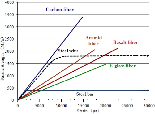
“FRP” is an acronym for fiber-reinforced polymers. The term composite material is a generic term used to describe the combination of two or more materials, which yield a product that is more efficient from its strength. The fibers provide the tensile strength, which are embedded in the matrix. The matrix provides protection and support for the sensitive fibers as well as local stress transfer from one fiber to another. The matrix, such as a cured resin-like epoxy, polyester, vinyl ester, or other matrix acts as a binder and holds the fibers in the intended position, giving the composite material its structural integrity by providing shear transfer capability. Three FRPs are commonly used (among others): composites containing glass fibers are called glass fiber-reinforced polymers (GFRP); those containing carbon fibers are called carbon fiber-reinforced polymers (CFRP); and those reinforced with aramid fibers are referred to as aramid fiber-reinforced polymers (AFRP). GFRPs are the most inexpensive compared to the other commercially available FRPs, consequently the most commonly used fibers in structural engineering applications. Moreover, the latest FRP composite is namely Basalt FRP (BFRP), which has developed within the last ten years and has higher tensile strength than E-glass fibers but lower than S-glass; however, its cost is near the cost of E-glass (Zhishen et al., 2012).
Typical stress-strain relationships of different FRPs compared to steel relationship are shown in Figure 2.1. FRP is linear elastic up to final brittle rupture when subject to tension while steel shows an elastic-plastic region. These curves give a clear contrast between the brittle behaviour of FRP composite and the ductile behaviour of steel. The fundamental difference between steel and FRP materials is due to the stress-strain behaviour of steel, which
after the initial linearly elastic phase displays the yielding plateau. Therefore, after reaching the maximum value corresponding to the yielding stress, the confinement pressure remains constant (neglecting strain hardening).
Figure 2.1: Typical stress-strain relationships of different FRPs compared to steel bars (Zhishen et al. 2012)
2.3 Manufacturing Processes of FRP Composites
Improving manufacturing technology is the greatest challenge today in the filed of composites. When composites are chosen for an application principally because of their properties, it is natural that the manufacturing methods would be chosen to optimize those properties. The earliest method of making composites was by manual layup, where each layer of the composites is put manually one above the other to produce the final layout. This consumes much time and needs a lot of skilled labor. This method was made easier using prepregs, which are fibers pre-impregnated with resin. Major advantages of the manual set up are that it has high versatility, but the accuracy is dependent on the skill of the worker and can yield goods with high volume fractions. Its major disadvantages are that it is slow, yields low production rates and there are health and safety issues, such as physical contact with the resin and its fumes [Taheri 1996].
2.3.1 Pultrusion Process
Pultrusion is an automated continuous composite manufacturing process. The major application of the pultrusion process is in the fabrication of composite parts that have a prismatic cross section profile. Pultrusion process is suited ideally for mass scale production. In this process, fibers are pulled through a resin bath to coat the reinforcement with the resin. Then excess resin is removed, as fibers are passed through heated die. Die completes the curing of the resin and controls the shape of the section. The major advantages of the pultrusion process are its capability to produce in high volume and being a very highly automated process. Its major disadvantages are the expensive die costs and its inability to produce products non-prismatic geometries [Hazra 2011]. Figure 2.2 shows a schematic of pultrusion process.
Figure 2.2: Schematic of pultrusion process [http://mdacomposites.org]
2.3.2 Resin Transfer Molding (RTM) Process
In this process, layers of fibers or prepregs are placed between male and female molds, and then they are pressurized and injected with resin. The resin is injected to fill all voids within the mold and thus penetrates and wets all surfaces of the reinforcing materials. A wide variety of reinforcement materials can be used. This process offers low waste and reduces machining cost of the finished product. The process can be automated. The major limitations of this process are manufacturing of complex shapes requires many trials, errors to ensure
proper wetting, and the mold designing is complex [Hazra 2011]. Figure 2.3 shows the schematic of RTM process.
Figure 2.3: Schematic of RTM process [http://mdacomposites.org]
2.3.3 Vacuum Assisted Resin Transfer Molding (VARTM) Process
Conceptually, this process is similar to RTM, but it is different on many accounts. First, VARTM is a single side process under a sealed enclosure and instead of the positive pressure used in RTM, vacuum is applied to the mold and sucked into the fabric-fiber. In this process, wetting of the fiber is dependent on the permeability of the preformed laminate and architecture of the fiber. Viscosity of the resin has to be low. This process is very safe from health hazard point of view as the entire system is under vacuum and can yield very high-quality products. Typical applications of VARTM include production of train seats, marine, complex aircraft and automotive parts [Hazra 2011]. Figure 2.4 shows a schematic of VARTM process.
Figure 2.4: Schematic of VARTM process [http://mdacomposites.org]
2.3.4 Compression Molding Process
Compression molding process is used in manufacturing sheet molding compound composites and bulk molding compound. This process consists of three stages, namely charging, compressing and ejecting. The material to be molded is preheated and placed in a mold in the charging stage. Then pressure and additional heat is applied in the compression stage. Finally, the finished product is removed from the mold after sufficient curing time. Major applications of the compression moldings are automotive components such as fenders, bumpers, and leaf springs. The major disadvantages of this process are that it cannot produce long fiber composite parts and mold costs cannot be justified for low production volumes. Also, resins with high shrinkage rates can cause waviness, ripples, sink marks and rough surfaces on the product [Hazra 2011].
2.3.5 Filament Winding Process
Filament winding is a type of composite manufacturing process, where controlled amount of resin and oriented fibers are wound around a rotating mandrel and cured to produce the required composite part. It was initially used to produce pressure vessels, water and chemical tanks. The development stage of filament winding goes back to dry wire winding of rocket motor cases, which requires reinforcement. Today, the applications include aircraft fuselages wing sections, helicopter rotor shafts, high-pressure pipelines, sports goods and structural applications of all types [Balya 2004]. The major advantages of the winding process are that filament winding machines are computer numerically controlled machines, highly automated and may be setup and operated in a matter of minutes, and capable of producing accurate repetitive fiber orientation. Moreover, it uses continuous lengths of fibers. Hence,
sections with very high strength-to-weight and stiffness-to-weight ratios can be manufactured [Mallick 2007]. However, the process has some limitations such as difficulty in placing fibers parallel to the axis of the mandrel, high mandrel cost, and special treatment on the external mandrel surface needed to ensure evenness. One primary tool used in the filament winding process is a precision ground mandrel that the fiber and resin are wound upon it. The mandrel is supported horizontally between a head and tail stoke. The tail stoke is free, but head stoke is driven by required angle and speed, using a computer program. As the mandrel rotates, a carriage travels along the mandrel and delivers fiber with a given position and tension. Carriage motion is also controlled by the computer in connection with head stoke rotation.
Fibers pass through a resin bath after tensioning system and gets wet before winding operation. When a pre-impregnated fiber or prepreg is used, wetting is not performed. Tensioning system is an important part of filament winding. This importance gets critical when winding at high angles. Since tension changes the friction force between fiber and the mandrel, it should be kept at a certain value during winding operation. Fiber tension also affects the volumetric ratio of composite at a given point. Excessive resin, due to a low tension, can result in decreased mechanical properties. Therefore, tensioning systems should be capable of rewinding a certain value of fiber. This condition occurs when fiber band reverses at the end of tube, while winding at low angles. Wetting can be done by two commonly used bathing types; drum bath and dip bath. Drum bath provide less fiber damage than dip bath. This is especially important when using carbon fibers. On the other hand, dip bath provides a better wetting action and mainly used with aramid or glass fibers. If fibers are not wetted in a desired way, air bubbles can be trapped between them and can cause voids in the composite part. Therefore, drum baths can be heated for a better wetting action. Lowering resin viscosity, reducing fiber speed, and increasing fiber path on the drum are other methods used for better wetting action. If heated resin is to be used, dip baths are preferred since drum surface cools as it leaves the resin bath.
The rotating mandrel can be a part of the produced composite part (a pressure vessel) or can be removed from the composite part. If it will be removed, a press should be used for removing. All mandrels, which will be removed, should have low thermal expansions in order to reduce residual stresses after curing action. In addition, surface finish is an important point, since an interface between the composite part and the mandrel is generally not permitted. If a
concave part is needed on the filament-wound part, a female mold can be used. In addition, excessive wet fiber can be used in order to fill the concave parts. Metal or composite parts can be mounted on mandrel in order to guide winding action such as pinrings or end-domes, which must be removable or collapsible. Sharp edges should be avoided in order not to cut fibers. Winding angle is the angle between the fibers and a line on the mandrel surface, which is parallel to mandrel axis. A maximum value, which is close to 90o, can be approximated. Very
low winding angle values need some arrangements at the ends of the mandrel, such as pin-rings [Balya 2004]. Figure 2.5 shows a schematic of the filament winding machine.
Figure 2.5: Schematic of filament winding machine [http://mdacomposites.org]
2.4 Prestressed Concrete
Prestressed concrete is a type of reinforced concrete in which the steel reinforcement has been tensioned against the concrete. This tensioning operation results in a self-equilibrating system of internal stresses (tensile stresses in the steel and compressive stresses in the concrete) which improves the response of the concrete to external loads. While concrete is strong and ductile in compression it is weak in tension, and hence its response to external loads is improved by applying a precompression. The basic concept of reinforced concrete, for both prestressed and non-prestressed construction, is that steel reinforcement is placed in those locations of a structure where tensile stresses will occur. In prestressed concrete construction, high strength reinforcement is used, and this reinforcement is tensioned prior to the application
of external loads. This initial tensioning of the reinforcement precompresses the surrounding concrete, giving it the ability to resist higher loads prior to cracking.
The prestressing operation is subdivided into two classifications, pretensioning and post-tensioning. In pretensioning the tendon is tensioned prior to casting the concrete, while in post-tensioning the tendon is tensioned after the concrete has been cast.
2.4.1 Pretensioning Technology
The first step in pretensioning is the stressing of high-strength steel tendons between the abutments of a pretensioning bed (see Figure 2.6 a). The concrete is then placed in the formwork. After the desired concrete strength has been reached, the tendons are detensioned and the member becomes prestressed (see Figure 2.6 b & c)
(a)
(b)
(c)
Figure 2.6: Stages of pretensioning, (a) Applying tension to tendons, (b) Casting of concrete, (c) Transferring of prestress.
Pretensioning is a common prefabrication technique, where the resulting concrete element is manufactured remotely from the final structure location and transported to site once cured. It requires strong, stable end-anchorage points between which the tendons are stretched.
These anchorages form the ends of a "casting bed" which may be many times the length of the concrete element being fabricated. This allows multiple elements to be constructed end-on-end in the one pre-tensioning operation, allowing significant productivity benefits and economies of scale to be realised for this method of construction. The amount of bond (or adhesion) achievable between the freshly set concrete and the surface of the tendons is critical to the pre-tensioning process, as it determines when the tendon anchorages can be safely released. Higher bond strength in early-age concrete allows more economical fabrication as it speeds production. To promote this, pre-tensioned tendons are usually composed of isolated single wires or strands, as this provides a greater surface area for bond action than bundled strand tendons.
2.4.2 Posttensioning Technology
The first step in producing a post-tensioned member is to place the reinforcing cages and the post-tensioning ducts in the formwork. After the casting and curing of the concrete, the tendons are tensioned and anchored using special post-tensioning jacks that react against the member. Unless unbounded tendons are being used, the duct then grouted to complete the post-tensioning operation. Figure 2.7 shows the post-tensioning technic.
Figure 2.7: Post-tensioning of the member
In the bonded tendon, the grout bonds the tendon to the surrounding concrete and provides corrosion protection for the tendon. The unbonded tendon is attached to the concrete only at its end anchors. Corrosion protection for the unbonded tendon is provided by grease-filled plastic tubes and by special details at the anchorages. Unbonded tendons are often used in applications such as post-tensioned two-way slabs where the small duct diameter, the low friction between the strand and the greased duct. With the unbonded tendons, special attention is required to ensure that the strand is protected from corrosion, where it enters the end anchorages. Further, it may be necessary to place additional reinforcing bars to provide adequate crack control. Besides, unbonded tensioning differs from bonded
post-tensioning by allowing the tendons permanent freedom of longitudinal movement relative to the concrete. Various proprietary post-tensioning systems are available. These systems differ in type of tendon that they employ, in the manner in which the tendons are tensioned, and in the anchorage devices which are used. There are four common types of tendon systems, monostrand tendons, single bar tendons, multi-wire tendons, and multi-strand tendons.
The relative advantages of posttensioning compared to the pretensioning are the flexibility in design for modern architectural building as well as it did not require a pre-stressing bed for the tensioning operation, thus allowing the tension process to start immediately when the concrete attains sufficient strength. Besides, an enough bond can be achieved by the end anchorages, not over the transmission length and the feasibility of replacing the prestressing tendons when they are damaged or failed. On the other hand, some of the relative disadvantages of posttensioning compared to pretensioning are the requirement of anchorage device and grouting equipment, the requirement of skilled and experienced workmanships as well as strong attention and frequent maintenance at end anchorage and tendons due to the corrosion problems.
2.4.3 Prestress Losses
The prestress losses for pretensioning and posttensioning can be calculated under the following three categories: losses at Jacking; losses at transfer, and time-dependent losses.
2.4.3.1 Losses at Jacking
Loss due to chuck slip (Δ fpCS): is calculated based on the difference between the final
elongation of the strand and elongation before release of the hydraulic jack. The change in strain in the strand is calculated by dividing the difference in elongations, by the total length of the strand, L. The stress loss due to chuck slip Δ fpCS is calculated by multiplying this strain
with the modulus of steel strand.
Loss due to Relaxation of Steel (Δ fpR1) (for pretensioned only): is calculated based on the
following equation suggested by PCI committee on Prestress Losses (1975) for low relaxation strand as:
![Figure 2.8: Nominal load versus deflection behavior of GFRP tube compared with steel spiral [Mandal and Fam 2006]](https://thumb-eu.123doks.com/thumbv2/123doknet/3344159.96532/40.918.237.707.708.1007/figure-nominal-versus-deflection-behavior-compared-spiral-mandal.webp)
![Figure 2.11: Behaviour of partially prestressed CFFTs, based on analytical modeling [Mirmiran and Shahaway 1999]](https://thumb-eu.123doks.com/thumbv2/123doknet/3344159.96532/45.918.242.705.164.465/figure-behaviour-partially-prestressed-analytical-modeling-mirmiran-shahaway.webp)