To cite this document:
Lv, Peng and Mohd Zawawi, Fazila and Benard, Emmanuel and
Prothin, Sebastien and Moschetta, Jean-Marc and Morlier, Joseph Adaptive proprotors as
applied to convertible MAVs. (2013) In: International Micro Air Vehicle Conference and
Flight Competition (IMAV2013) , 17-20 Sep 2013, Toulouse, France.
O
pen
A
rchive
T
oulouse
A
rchive
O
uverte (
OATAO
)
OATAO is an open access repository that collects the work of Toulouse researchers and
makes it freely available over the web where possible.
This is an author-deposited version published in:
http://oatao.univ-toulouse.fr/
Eprints ID: 9319
Any correspondence concerning this service should be sent to the repository
administrator:
[email protected]
Adaptive proprotors as applied to convertible MAVs
Peng Lv
∗, Fazila Mohd-Zawawi
†, Emmanuel Benard
‡,
Sebastien Prothin
§, Jean-Marc Moschetta
¶and Joseph Morlier
k1 Université de Toulouse; ISAE, DAEP;
10 av. Edouard Belin - BP 54032 - 31055 Toulouse Cedex 4, France [email protected]
2 Université de Toulouse; Institut Clément Ader; ISAE, UPS, EMAC, INSA;
10 av. Edouard Belin - BP 54032 - 31055 Toulouse Cedex 4, France [email protected]
Abstract
A passive twist control is considered as an adaptive way to maximize the overall efficiency of a proprotor developed for convertible Micro Air Vehicles (MAV). Incorporated into a database of airfoil characteristics, Blade Element Momentum Theory (BEMT) is implemented to predict the performance of proprotors at low Reynolds numbers. Using this model, it is found that low twist allows for efficient hovering while high twist helps to forward flight. The Centrifugal Force Induced Twist (CFIT) concept is proposed to realize the required torsion of proprotor between hover and forward flight. Tip mass is used to provide the nose-down twisting moment by centrifugal force and stabilize the flexible blade. Classical Lamination Theory (CLT) is employed to estimate the torsion behavior of glass/epoxy laminate blade and to study the feasibility of CFIT concept. The results indicate that the predicted torsion of CFIT blade is of the same level with required deformation. The laminate blades were tested in hover and forward flight modes, with deformations measured by Laser Displacement Sensor (LDS). In rotor mode, the laminate blade can generate approximately -9◦torsion at blade tip rotating at 1,300 RPM. By contrast, at
800 RPM and inflow velocity 8m/s, it is capable of providing around -5◦ torsion at blade tip in
propeller mode.
1
Introduction
Convertible rotor aircraft has been developed for versatility services for several years, as it combines the merits of a helicopter and and airplane. It has the capacity of Vertical/Short TakeOff and Landing (VSTOL) like a helicopter, through tilting rotor, then converts to forward flight at relatively high speed, as an airplane. The three main convertible rotor configurations are the tilt-rotor, tilt-wing and tilt-body. Tilt-rotor aircraft was developed in early 1950s, exemplified by the Bell XV-3 operating the first transition from hover to forward flight. In 1970s, XV-15 demonstrated the feasibility of rotor concept. The success of XV-15 led to the V-22 project, leading to the first production tilt-rotor aircraft in the world. Recently, the tilt concept has attracted the attention of MAV research
∗PhD student, DAEP, ISAE †PhD student, DAEP/DMSM, ISAE ‡Associate Professor, DAEP, ISAE §Researcher, DAEP, ISAE ¶Professor, DAEP, ISAE kProfessor, DMSM, ISAE
community. In 2008, Shkarayev and Moschetta introduced the concept of tilt-body MAV, which has a tilt-body configuration and is capable of flying in hover and forward flight [1]. This configuration of tilt-body MAV which was successfully tested in flight.
Designing a proprotor to operate efficiently in hover and forward flight presents a challenge since the inflow velocity and thrust requirement for each flight condition are quite distinct. In hover, the inflow velocity is small and the proprotor must provide high thrust to support the aircraft weight. By contrast, in forward flight, the inflow velocity is relatively large and the low thrust must only overcome the drag. The difference in the inflow and thrust requirements between the two flight modes suggests different blade twist and chord distributions. In terms of twist effect on efficiency, high blade twist on the proprotor allows the aircraft to fly faster and more efficiently, whereas low blade twist increases the efficiency in hover. In 1983, McVeigh obtained the twist of XV-15 proprotor through linear interpolation of twist between ideal rotor and propeller by a compromise analysis [2]. Although this trade-off solution provided an acceptable performance on XV-15, the stiff proprotor with certain twist cannot maximize the efficiency for both flights. In 1988, Nixon proposed a passive blade twist control for the proprotor on XV-15 [3]. The study demonstrated successfully the feasibility of the passive blade control on conventional tilt-rotor aircraft. The small proprotors also suffer the problem caused by different twist between hover and forward flight. However, due to the small size of MAV, the complex tailored cross section of blade for passive twist control based on conventional tiltrotor aircraft is not available any more. Therefore, based on CFIT concept, composite laminate is proposed to be a more practical method for proprotor blade of MAV.
A key issue to study flexible blade is to use validated predictive simulations and therefore, in the domain of aeroelasticity, to measure accurately deformations. Optical measurement techniques have been developing for some years in aerodynamics, materials and structure, such as Holographic Inter-ferometry (HI), Electronic Speckle Pattern InterInter-ferometry (ESPI), Projection Moiré InterInter-ferometry (PMI) and Digital Image Correlation (DIC) [4]. In 1998, Fleming obtained the 3-D deformation of rotor blade using PMI technique [5]. However, it has low sensitivity for in-plane deformation and moderate for out-of-plane deformation. By contrast, DIC has a relatively high sensitivity that can reach 1/30,000 of the test field [6]. In 2011, Lawson demonstrated the deformation of a rotating blade using DIC [7]. The technique was found to have many advantages including high resolution results, non-intrusive measurement, and good accuracy over a range of scales. However, DIC needs a preprocessing which is to apply a stochastic speckle pattern to the surface by spraying it with a high-contrast and non-reflective paint. This complex painting will probably affect the stiffness of small MAV blades. Hence, in this study, LDS based method was developed to measure blade deformation in both of hover and forward flight.
2
Optimum twist of MAVion proprotor
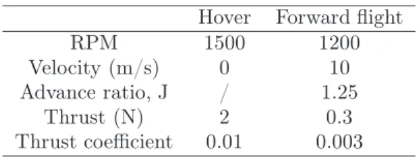
MAVion, a tilt-body MAV developed by ISAE, is designed to fly in both hover and forward flight, as shown in Fig. 1. The typical wing Reynolds number of its operation conditions is below 100,000. In hover mode, the nominal thrust coefficient is 0.1 while it becomes 0.03 in forward flight. The detailed operation conditions are shown in Tab. 1.
To obtain the optimum twist distributions of proprotor in hover and forward flight, the spec-ifications of MAVion proprotor are presented in Tab .2 as arbitrary constraints. Flat plate cross section was used as airfoil of flexible blades since it is relatively practical for CFIT concept study in terms of fabrication. In addition, thin plates, cambered or flat, with extremely thin leading edge, exhibit characteristics less sensitive to variations in Reynolds number and turbulence[8]. These airfoils achieved better lift-to-drag ratios than conventional airfoils at low Reynolds numbers. On one hand,
Figure 1: Wind tunnel model of MAVion.
Hover Forward flight RPM 1500 1200 Velocity (m/s) 0 10 Advance ratio, J / 1.25
Thrust (N) 2 0.3 Thrust coefficient 0.01 0.003
Table 1: Operation conditions of MAVion
the thickness of flat plate should be thin enough for aerodynamic performance. On the other hand, it is necessary to consider the stacking thickness of potential adaptive proprotor based on composite materials. Hence, flat plate with thickness 2.5% was selected as the airfoil for proprotor. Five linear built-in twists of proprotor are defined first, i.e. -10◦, -15◦, -20◦, -25◦and -30◦blade tip twist relative
to root. Based on airfoil characteristics from XFOIL [9], BEMT was used to compute airloads and
Number of blades 2
Stacking axis of airfoils 0.25 on the chord Pitch axis 0.25 on the chord
Airfoils Flat plate
Chord 0.03m
Radius 0.2m
Hub radius 0.03m Table 2: MAVion proprotor specifications
to analyze the efficiencies in rotor and propeller modes. It has been implemented and validated in a previous study [10]. The optimum twist distributions for hover and forward flight is found when the efficiencies of rotor and propeller can be maximized, respectively.
In rotor mode, after the inflow ratio λ is determined, the induced power coefficient CPi, the profile
[11]: CPi = Z r=1 r=0 4λ(r)3rdr, (1) CP0 = σ 2 Z r=1 r=0 Cd(r)r3dr, (2) FM = CPideal CPmeas = C 3/2 T / √ 2 CPi+ CP0 . (3)
Where r is the non-dimensional radius, dr is the non-dimensional length of each element, σ is the local solidity, Cd is the local drag coefficient and CT is the thrust coefficient.
In propeller mode, the propulsive efficiency η is defined by conventional trust and power coefficients: CT = (π3/4)σCyr3F2/[(F + σK′)cos(φ)]2, (4)
CP = CTπrCx/Cy. (5)
η = CTJ/CP, (6)
where J is the advance ratio, Cx and Cy are the propeller force coefficients, F is Prandtl’s tip-loss
factor, K′is equivalent interference factor and φ is the inflow angle. Propeller performance is typically
described by plots of CT, CP and η vs J.
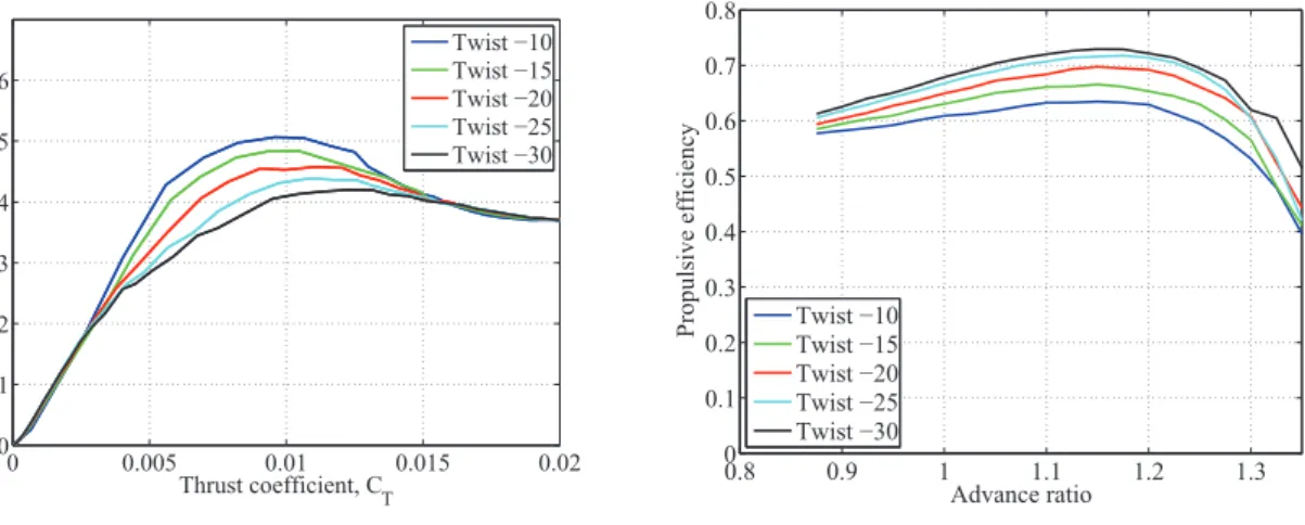
Fig. 2(a) shows the twist effect on hovering efficiency - Figure of Merit (FM) - with the variation to thrust coefficient. Thrust coefficient is adjusted by collective pitch for the five blades with built-in twist -10◦, -15◦, -20◦, -25◦and -30◦, respectively. The blade with built-in twist -10◦has the maximum
efficiency at CT=0.01. In Fig. 2(b), the propulsive efficiencies of the five blades are all analyzed for
a fixed value CT=0.003. They vary with the advance ratios in forward flight. The blade with twist
-30◦ exhibits the highest efficiency of all, at advance ratio J=1.25. Overall, high twist of blade is
beneficial for forward flight while low twist can improve hovering efficiency. According to the mission requirement of MAVion, the solution of proprotor for MAVion is given in Tab. 3.
0 0.005 0.01 0.015 0.02 0 0.1 0.2 0.3 0.4 0.5 0.6 Thrust coefficient, C T FM Twist −10 Twist −15 Twist −20 Twist −25 Twist −30
(a) Twist effect on rotor efficiency
0.8 0.9 1 1.1 1.2 1.3 0 0.1 0.2 0.3 0.4 0.5 0.6 0.7 0.8 Advance ratio
Propulsive efficiency Twist −10
Twist −15 Twist −20 Twist −25 Twist −30
(b) Twist effect on propeller efficiency
Hover Forward flight Built-in twist (degree) -10 -30 Collective pitch (degree) 31 54
Table 3: Optimum proprotor of MAVion
3
Concept of adaptive proprotor
CFIT concept aims at realizing a deformable, durable and stable blade for MAV proprotor, which are characterized by the deformation, failure performance and dynamics behavior. The initial step of the procedure is to select suitable reinforcing fiber for the laminate blade. The significant factor to select a reinforcing fiber for small-scale proprotor is linked to its tailoring capacity. Glass/epoxy was determined for the MAV flexible proprotor in current study. In order to improve the aerodynamic performance of flat plate at low Reynolds number, the thickness of laminate blade should be thin enough to provide a low thickness-to-chord ratio. Thus, two typical laminate configurations are considered here, a symmetric laminate [θ θ]T, and a antisymmetric laminate [θ − θ]T. A critical issue
in the design of a laminate blade is failure analysis. The comparison of strength of UD and angle-ply laminates was described based on a typical carbon/epoxy composite (AS4/3501-6) using first angle-ply failure analysis [12]. All of the uniaxial tensile strength, uniaxial compressive strength and in-plane shear strength of the angle-ply laminate are evidently higher than those of the off-axis UD material. Thus, in current study, antisymmetric laminates [θ − θ]T are employed as balanced laminates. The
layup of specimen in the current study is selected as [45 − 45]T.
The Classical Lamination Theory (CLT) demonstrates that, for a general composite laminate, the forces and moments on it are related to the strains and curvatures at reference surface. The 6×6 matrix consisting of the components Aij, Bij, and Dij (i, j = 1, 2, 6) is the laminate stiffness matrix,
is also called ABD matrix. In order to be able to obtain the strains and curvatures at the reference surface in terms of the force and moment resultants, the ABD matrix is inversed and then becomes the laminate compliance matrix consisting of the components aij, bij, and bij. The torsion can be
directly given by the curvature:
κ0xy= b16Nx+ b26Ny+ b66Nxy+ d16Mx+ d26My+ d66Mxy (7)
Where the Nx, Ny and Nxy are the tensile forces in the directions of x, y and xy. Besides, Mx, My
and Mxy represent the moments in varied directions. Terms b16, b26, b66, d16, d26 and d66 are the
corresponding compliance factors.
The adaptive proprotor should not only be flexible to produce the required deformation, but also stable to maintain the required twist in each of flight mode. For a stable blade, the blade CG must be ahead of the aerodynamic center [13]. Hence, in CFIT flexible concept, tip mass is designed to adjust the global CG of laminate blade. In addition, tip mass is beneficial for improving the nose-down twisting moment and increasing the torsion of laminate blades. On one hand, tip mass is required to be heavy enough to be able to adjust the global CG. On the other hand, it should be light enough to provide weight efficiency for the application on MAVs. Tab. 4 shows the basic parameters on the blade with tip mass. In order to estimate the twist of laminate blades, the tensile force and twisting moment of a spinning blade are introduced to CLT model. At any local section of blade, the total centrifugal force and total nose-down moment are defined by [13]:
Nx(y) = Fcf(y) =
Z R y
Table 4: Basic parameters of blade Weight of blade 7.0g Weight of tip mass 6.5g Chord 30mm Length 185mm Radius 200mm Thickness of blade 0.75mm Length of tip rod 35.0mm Diameter of tip rod 5.0mm
Diameter of tube 7.0mm
kL Feathering axis
L Tip rod
Figure 3: Definition of rotating axis factor k
Mxy(y) = Mnd(y) = IθΩ2(R − y)sin(θ) + ITΩ2sin(θT). (9)
Where x is the chordwise coordinate, y is the spanwise coordinate, R is the proprotor radius, Ω is the rotation speed, my is the local mass of laminate blade and mT is the tip mass. In addition, θ
is the local twist angle and θT represents the twist angle at the blade tip. The torsional moment of
inertia of the blade Iθ is small compared to the torsional moment of inertia of the tip rod IT, thus
the nose-down moment acting on the blade airfoil is negligible compared to the nose-down moment acting on the tip mass. Similarly, the centrifugal force on the blade airfoil is negligible compared to the one on the tip mass. Hence,
Fcf(y) = mTΩ2R, (10)
Mnd(y) = ITΩ2sin(θT). (11)
The moment of inertia of the tip rod IT is defined as:
IT =
Z (1−k)L
−kL
ρx2sdx. (12)
Where L is the length of tip rod and k is the rotating axis factor. k is used to define the distance from one side of tip rod to the twisting axis, as shown in Fig. 3. For example, k=0.5 means that the twisting axis is on the midpoint of tip rod. If k is between 0 and 1, the twisting axis is on the tip rod. Else, the tip rod rotates about the off-body axis. Changing density ρ with mass m, section area s and rod length L, it becomes:
IT = Z (1−k)L −kL m sLx 2sdx = m 3L[((1 − k)L) 3 − ((−k)L)3]. (13)
−1 −0.5 0 0.5 1 1.5 2 −30 −25 −20 −15 −10 −5 0 k
Tip twist, deg
Collective pitch 35°
Collective pitch 55°
Figure 4: Predicted torsion of adaptive blade
Here, the twist behavior of laminate blades with low and high collective pitches based on 1,500 RPM. As discussed above, low collective pitch requires low twist for rotor mode while high twist is needed at high collective pitch for propeller mode. As it can be seen in Fig. 4, at both low and high collective pitches, the tip torsion shows the symmetrical behavior with respect to k=0.5 since the torsional moment of inertia of tip rod IT at k=0.5 is minimum. Through sliding the tip rod, the CFIT concept
blade can achieve the beneficial torsion at the required level.
The final laminate blades with tip masses are shown in Fig. 5. The bending and torsion distri-butions during rotation are considered as the blade deformation, since beneficial torsion can increase the overall performance while bending tends to decrease the thrust.
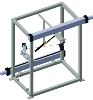
Figure 6: LDS rig model
4
Testing and discussion
In order to measure the deformation of rotating laminate blade, a LDS system was developed, as shown in Fig. 6. To avoid any disturbance on flow field, the two LDSs were fixed at an incidence angle to measure the blade deformation. The LDS used in this experiment is a KEYENCE LK-G502. The sampling frequency was set to 10,000Hz. Diffuse reflection mode of LDS was used for measurements. The distance of reference was 500mm, and the range of measuring was between -250mm to 500mm. For a long range measurement, the measuring accuracy is typically ±0.1% of Full Scale (FS). In
40 60 80 100 120 140 160 180 200 −20 −10 0 −25 −20 −15 −10 Span, mm Chord, mm mm −24 −22 −20 −18 −16 −14 −12 −10 −8 −6
(a) Rotor mode: RPM 1,300
40 60 80 100 120 140 160 180 200 −20 −10 0 −20 −10 0 Span, mm Chord, mm mm −25 −20 −15 −10 −5 0
(b) Propeller mode: RPM 800 and inflow 8m/s
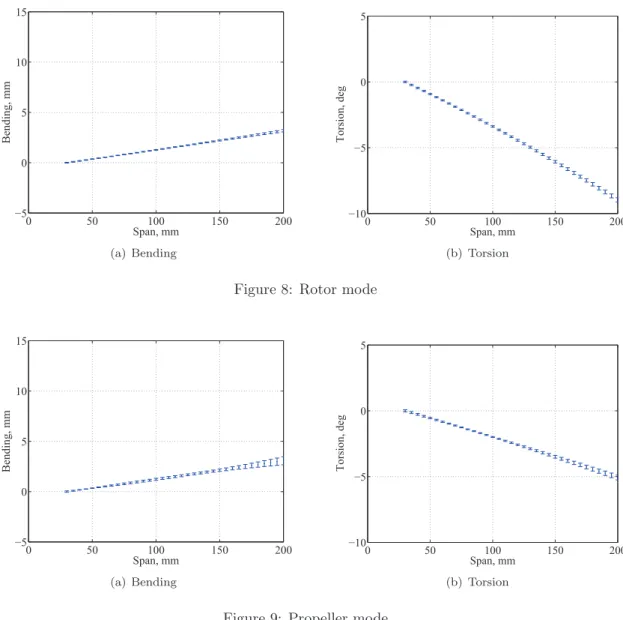
0 50 100 150 200 −5 0 5 10 15 Span, mm Bending, mm (a) Bending 0 50 100 150 200 −10 −5 0 5 Span, mm Torsion, deg (b) Torsion
Figure 8: Rotor mode
0 50 100 150 200 −5 0 5 10 15 Span, mm Bending, mm (a) Bending 0 50 100 150 200 −10 −5 0 5 Span, mm Torsion, deg (b) Torsion
Figure 9: Propeller mode
order to reconstruct the deformed blade and to extract the bending and torsion, the post-processing methodology based on polynomial surface fitting was developed for LDS technology, including error propagation of measurement based on the Kline-McClintock method [14].
The results on shape reconstruction are shown in Fig. 7. In both hover and forward flight, the obvious deformation occurred during rotation. The detailed bending and torsion were extracted according to surface function. From Figs. 8 and 9, it was found that the CFIT blade is capable of generating -8.96◦ torsion at RPM 1,300 in hover mode. In propeller mode, with high collective pitch,
it generated around -5◦torsion at RPM 800, inflow 8m/s. Meanwhile, the maximum values of bending
at blade tip are less that 5mm for both modes. In propeller mode, the blade can afford inflow and keep away from large bending.
5
Conclusion
The BEMT results showed high twist of blade is suitable for propulsive efficiency while low twist is beneficial for hovering efficiency. The CFIT concept of adaptive proprotor was verified first by CLT model. Glass/epoxy was used for the adaptive proprotor with the antisymmetric stacking sequence. A post-processing methodology was proposed to reconstruct deformed blade based on LDS technique, including uncertainty analysis based on Kline-McClintock method. In both of hover and forward flight, the adaptive proprotor produced evident torsion. However, the torsion generated in propeller mode was not capable of reaching the required twist. In coming tests, the motor of high torque capacity is expected to be used for high RPM and torsion. The adaptive proprotor based on CFIT concept showed the application on MAVion. The developed models and LDS technique are reliable tools for designing and analyzing the proprotor made of composite material.
References
[1] S. Shkarayev, J. M. Moschetta and B. Bataille, Aerodynamic Design of Micro Air Vehicles for Vertical Flight(Journal of Aircraft, Vol. 45, No. 5, 2008) pp. 1715-1724.
[2] M. A. McVeigh, H. J. Rosenstein and F. J. McHugh, Aerodynamic Design of the XV-15 Advanced Com-posite Tilt Rotor Blade (39th Annual Forum of the American Helicopter Society, St. Louis, MO, May 1983).
[3] M. W. Nixon, Improvements to Tilt Rotor Performance through Passive Blade Twist Control (NASA Technical Memorandum 100583, April 1988).
[4] S. Rajpal, Optical Methods of Measurement: Whole-field Techniques (Second edition, Francis and Tay-lor/CRC Press, 2009).
[5] G. A. Fleming and S. Gorton, Measurement of Rotorcraft Blade Deformation Using Projection Moiré Interferometry (Proceedings of the 3rd International Conference on Vibration Measurements by Laser Techniques: Advances and Applications, SPIE the International Society for Optical Engineering, Ancona, Italy, June 1998) pp. 514-527.
[6] T. Schmidt and J. Tyson, Full-Field Dynamic Displacement and Strain Measurement Using Advanced 3D Image Correlation Photogrammetry: Part 1(Experimental Techniques, Vol. 27, No. 3, 2003) pp. 47-50. [7] M. S. Lawson and J. Sirohi, Measurement of Deformation of Rotating Blades Using Digital Image
Corre-lation (Proceedings of 52nd AIAA/ASME/ASCE/AHS/ASC Structures, Structural Dynamics and Ma-terials Conference, Denver, Colorado, April 2011).
[8] B. J. Hein and I. Chopra, Hover Performance of a Micro Air Vehicle: Rotors at Low Reynolds Number (International Specialists Meeting Unmanned Rotorcraft: Design, Control ans Testing, Chandler, AZ, January 2005).
[9] M. Drela, XFOIL 6.9 User Guide (Massachusetts Institute of Technology, 2001).
[10] P. Lv, S. Prothin, F. M. Zawawi, E. Benard, Joseph Morlier and J. M. Moschetta, Study of A Flexible Blade for Optimized Proprotor (ERCOFTAC International Symposium, Unsteady Separation in Fluid-Structure Interaction, Mykonos, Greece, June 2013).
[11] J. G. Leishman, Principles of Helicopter Aerodynamics (Cambridge Aerospace Series, 2nd edition, 2006). [12] I. M. Daniel and O. Ishai, Engineering Mechanics of Composite Materials (Oxford University Press 1994). [13] J. Sicard, Investigation of an Extremely Flexible Stowable Rotor for Micro-helicopters (Master’s thesis,
University of Texas at Austin, May 2011).
[14] S. J. Kline and F. A. McClintock, Describing Uncertainties in Single-Sample Experiments (Mechanical engineering, Vol. 75, January 1953) pp. 3-8.