Contents lists available atScienceDirect
Journal of Power Sources
journal homepage:www.elsevier.com/locate/jpowsour
Electrochemical performances of Li
4
Mn
5
O
12
films prepared by spray-coated
sol-gel reaction
Christelle Alié
a,∗, Cédric Calberg
a, Carlos Páez
a, Dimitri Liquet
b, David Eskenazi
b,
Benoît Heinrichs
a, Nathalie Job
aaUniversity of Liège, Department of Chemical Engineering - Nanomaterials, Catalysis, Electrochemistry, B6a Quartier Agora, 13 Allée du VI Aout, 4000, Liège, Belgium bPrayon S.A., 144 rue J Wauters, 4480, Engis, Belgium
H I G H L I G H T S
•
Li4Mn5O12films have been prepared by spray coating and sintering.•
Films show superior rate performances and good stability compared to powder samples.•
Theoretical capacity of 163 mAh g−1has been attained.•
Specific capacity of 330 μAh cm−2has been achieved.A R T I C L E I N F O
Keywords:
Li4Mn5O12cathode Thin film battery Spray coating Cycling stability
A B S T R A C T
The electrochemical performances of Li4Mn5O12powders prepared via an aqueous sol-gel method using either
citric acid orL-lysine as complexing and combusting agent are compared. At current rate of 0.1 C, a discharge
capacity of 163 mAh g−1and a good cyclability are obtained for powder cathode materials prepared withL
-lysine and processed as composite electrode. Films of the corresponding Li4Mn5O12were deposited by direct
spray coating of precursors' solutions and subsequent thermal treatment at 400 °C. Films exhibit better elec-trochemical performances than powders with a discharge capacity of up to 165 mAh g−1at 0.1 C and a capacity
retention of 95% after 100 cycles at 0.5 C and 89% after 100 cycles at 2 C. Increasing the active material loading up to 2 mg cm−2leads to a small loss of cyclability, especially at high cycling rates, but a specific capacity of 275
μAh cm−2is still achieved at 2 C. These values of specific capacities are higher than those observed in the
literature for lithium manganese oxide films.
1. Introduction
During the past decades, rechargeable lithium and lithium-ion batteries have been extensively investigated and broadly used in a wide variety of portable electric devices owing to their high energy densities [1–4]. Lithium manganese oxides are a promising cathode material for lithium-ion batteries on account of advantages such as a good rate ca-pacity, high electrode potential, high abundance of Mn on earth, low cost, low toxicity and good safety [5–7]. Among them, the spinel LiMn2O4has become of particular interest [8–10]. However, large ca-pacity fade upon cycling is encountered due to Jahn-Teller distortion as the average valence of manganese falls below +3.5 in LiMn2O4 [11,12]. The anisotropic expansion/contraction of the unit cell that occurs during discharge/charge destroys the structural integrity of
spinel cathodes and significantly reduces the cycling efficiency. With a manganese oxidation state of +4, the Jahn-Teller distortion can be suppressed in spinel Li4Mn5O12 [13]. Li4Mn5O12 is an attractive cathode for rechargeable 3 V lithium batteries because it exhibits a theoretical capacity of 163 mAh g−1in the 3 V region (i.e. 2.0–3.5 V vs. Li/Li+), corresponding to the insertion of 3 lithium atoms per formula unit, while no capacity is expected in the so-called 4 V region (i.e. 3.5–4.3 V vs. Li/Li+) as this would mean that no pure Li4Mn5O12has been obtained [14,15].
However, preparing Li4Mn5O12with appropriate properties is not straightforward. Li4Mn5O12powders are usually synthesized by a solid state reaction that involves the mechanical mixing of lithium and manganese salts followed by a long period of calcination and extended grinding [13,15–18]. On the one hand, it is difficult to synthesize
well-https://doi.org/10.1016/j.jpowsour.2018.09.081
Received 7 June 2018; Received in revised form 11 September 2018; Accepted 23 September 2018
∗Corresponding author.
E-mail address:c.alie@uliege.be(C. Alié).
Available online 06 October 2018
0378-7753/ © 2018 Elsevier B.V. All rights reserved.
crystallized Mn4+spinels due to the concomitant formation of Mn3+by the reduction of tetravalent manganese ions at 400 °C or above. Indeed, Li4Mn5O12 is unstable under heat treatment and disproportionates to LiMn2O4and Li2MnO3at more or less high temperature, depending on synthesis conditions [14,19]. On the other hand, it is well known that the electrochemical performances of the cathode are strongly affected by the physical properties such as the particle morphology, the crys-tallinity and the composition of the material [20,21]. Both issues are of course linked. Indeed, solid state reaction synthesis of lithium manga-nese oxides has several disadvantages: it often leads to irregular mor-phology, large particle size and broad particle size distribution and it does not allow a good control of the stoichiometry. The final electro-chemical performances are thus difficult to control.
A possibility to overcome these problems is the use of sol-gel tech-nique to prepare the electrode materials. Sol-gel method has indeed been recently introduced for the synthesis of high performance active materials for positive electrode in rechargeable lithium and lithium-ion batteries [8,9,22] as this method has several advantages, such as lower calcination temperature and shorter processing times, and leads to sub-micron sized particles with a narrow size distribution. Achieving a highly pure Li4Mn5O12powder by sol-gel process is a decisive feature for high battery performance.
Besides the development of lithium manganese oxide powders for application as relatively thick composite electrodes with carbon as conductive additive and a binder, extensive research has been per-formed on the development of lithium and lithium-ion microbatteries. These microbatteries are utilized in various application fields related to microsystems in consumer and medical electronics. Literature reports on thin films of LiMn2O4 synthesized by a variety of techniques, in-cluding sputtering [23,24], pulsed laser deposition [25,26], electro-static spray deposition [27] and chemical processing via a wet route [28,29]. The overall capacity of the battery being linked to the amount of material deposited, film deposition techniques able to achieve high loading with minimum coating times should be developed for economic reasons.
In the present work, we report on the preparation and electro-chemical characterization of pure Li4Mn5012films with high loadings deposited by an innovative rapid method. Loadings up to 2 mg cm−2 have been developed using spray coating of sol-gel derived precursors' solutions. First we performed a screening of syntheses of Li4Mn5O12 powders prepared by sol-gel process in order to select the synthesis leading to the best electrochemical properties in terms of specific ca-pacity and caca-pacity retention. These Li4Mn5O12powders were tested as composite electrodes made of the active material, carbon as electrical conductor additive and a binder (PVDF). The three synthesis methods studied were chosen for the easiness of the process in view of scale-up and compatibility with the spraying technique. They are based on re-sults previously reported in the literature by other research groups. On the one hand, Li4Mn5O12 was synthesized similarly to Li4Mn5O12 powders developed for supercapacitor applications [30,31]. On the other hand, the synthesis conditions of LiMn2O4[32] and Li2MnO3[33] were adapted to the synthesis of Li4Mn5O12. In a second step, the synthesis route leading to materials with the best electrochemical properties in composite electrode configuration was selected; the recipe was updated for direct spray coating of precursors’ solutions to deposit pure Li4Mn5O12as thin film on stainless steel discs used as substrate and current collector. The electrochemical performances of the obtained films were then measured and compared to that of the corresponding powder and to results reported in the literature.
2. Experimental section
2.1. Powder synthesis and characterization
Three ways of preparation of Li4Mn5O12by sol-gel process were investigated and the powders obtained were tested as composite
electrodes combining the active material with a conductive additive and a binder.
The first synthesis route is inspired by Hao et al. and Thackeray et al. [30,33]. Lithium acetate (CH3COOLi.2H2O, Sigma Aldrich 98%, 1.6 × 10⁻²mol) and manganese acetate ((CH3COO)2Mn.4H2O, Aldrich 99%, 2 × 10⁻²mol) were dissolved in 15 mL deionized water; the Li:Mn molar ratio was chosen as 4:5. The precursors' solution was mixed with an aqueous solution of citric acid (Sigma Aldrich 99%, 3.6 × 10⁻²mol in 10 mL deionized water) which acts as complexing and combusting agent. The pH was adjusted to 8.5 with either addition of ammonia to the citric acid solution before mixing with the pre-cursors' solution [33] or addition of ammonia after mixing the citric acid solution with the precursors' solution [30]; the citric acid to total metal ions molar ratio was 1:1. The stirred solution was then heated at 75 °C and kept at that temperature until a viscous gel was obtained (1.5 h). After drying under vacuum (100 mbar) at 100 °C, the solid was ground in an agate mortar for 5 min, preheated in air at 300 °C for 2 h, mortar-ground again for 5 min and further calcined in air at 400 °C for 10 h or 500 °C for 4 h. Hereafter, the final products are named P1A400, P1A500, P1B400 and P1B500. In these names, P corresponds to ‘powder sample’, 1 stands for ‘first synthesis method’, A or B for the adjustment of pH after or before mixing the citric acid solution with the precursors' solution, respectively, and 400 or 500 is the temperature of calcination.
The second preparation method is inspired by Hwang et al. and Thackeray et al. [32,33]. First, manganese nitrate (Mn(NO3)2.4H2O, Alfa Aesar 98%, 2 × 10⁻²mol) was dissolved in deionized water (15 mL) and solid lithium nitrate (LiNO3, Fluka 98%, 1.6 × 10⁻²mol) was added progressively. The precursors' solution was mixed with an aqueous solution of citric acid (Sigma Aldrich 99%, 3.6 × 10⁻²mol in 15 mL deionized water). Like for synthesis 1, the pH was adjusted to 6 with either addition of ammonia to the citric acid solution before mixing with the precursors' solution or addition of ammonia after mixing the citric acid solution with the precursors' solution (molar ratio of citric acid to total metal ions of 1:1). The solution was then heated at 80 °C and kept at that temperature until a viscous gel was obtained (1.5 h). After drying under vacuum (100 mbar), the solid was preheated in air at 300 °C for 6 h, mortar-ground for 5 min and further calcined in air at 400 °C for 10 h. The final products were respectively named P2A400 and P2B400 where ‘P2’ corresponds to a powder prepared by synthesis route 2, A or B stands for the adjustment of pH after or before mixing with precursors, respectively, and 400 refers to the temperature of calcination. The third synthesis method is inspired by Zhao et al. [31] who introduceL-lysine instead of citric acid to play the role of
com-plexing and combusting agent and to adjust the pH without addition of ammonia. Lithium acetate (CH3COOLi.2H2O, Sigma Aldrich 98%, 1.6 × 10⁻²mol), manganese acetate ((CH3COO)2Mn.4H2O, Aldrich 99%, 2 × 10⁻²mol) andL-lysine (Alfa Aeasar 98%,L-Lysine to total metal ions molar ratio equal to 1:50) were ground together in an agate mortar for 5 min and then dissolved in deionized water (20 mL). The solution was heated to 80 °C and kept at that temperature until a vis-cous gel was obtained (1 h). After drying under vacuum (100 mbar) at 100 °C, the solid was mortar-ground for 5 min, preheated in air at 300 °C for 2 h, mortar-ground again for 5 min and further calcined in air at 500 °C for 4 h. The final product was named P3_500 where ‘P3’ corresponds to a powder prepared by the third synthesis route and 500 stands for the temperature of calcination.
The as-prepared products were characterized by X-ray powder dif-fraction (Siemens D5000 powder diffractometer, CuKα radiation) and scanning electron microscopy (Philips ESEM-XL30). The electro-chemical properties of the products were investigated on a multi-channel battery tester (Bio-Logic VMP3) using CR2032 coin-type cells. For the screening of the powders, the composite electrodes were fab-ricated by intimately mixing the active material Li4Mn5O12(75 wt.%) and carbon (Timcal Super C65, 15 wt.%) by ball milling followed by mixing with polyvinylidene fluoride PVDF (10 wt.%) in N-methyl
2-pyrrolidone as solvent for 1 h to form a homogeneous slurry. The solid and solvent amounts were adjusted to obtain a slurry that can be easily coated using a doctor blade technique onto an aluminum current col-lector. The electrodes were dried under vacuum (20 mbar) at room temperature for 16 h; after drying, the material peels off as a solid flexible membrane. This membrane was punched out and weighed; the typical active material loading was around 2.5–3.0 mg cm−2. The coin cell batteries were assembled in an argon-filled glove box (MB 200B)
with the composite membrane as positive electrode, a Li metal foil as counter-electrode, a layer of separator (2 Celgard®2730 membranes) and two stainless steel discs as fillers. 1 M LiPF6in ethylene carbonate/ diethylcarbonate (EC:DC 1:1, w/w, Merck) was used as electrolyte. Cyclic voltammograms (CVs) were measured at a scan rate of 0.1 mV s−1between 1.5 and 4.5 V vs. Li/Li+and galvanostatic cycling was performed between 1.8 V and 3.6 V vs. Li/Li+at 0.1C (i.e. 10 h to fully charge/discharge the electrode, assuming that the active material
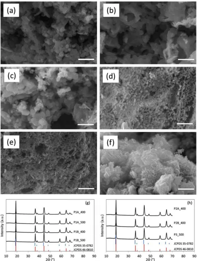
Fig. 1. SEM micrographs of Li4Mn5O12. (a) P1A400, (b) P1A500, (c) P1B400, (d) P2A400, (e) P2B400, and (f) P3_500. On each figure, the bar represents 1 μm. XRD
patterns of Li4Mn5O12powder samples (g and h). Standard XRD patterns of Li4Mn5O12(JCPDS 46-0810) and LiMn2O4(JCPDS 35-0782) are presented for
displays a capacity of 163 mAh g−1, corresponding to the theoretical capacity of Li4Mn5O12). All characterizations were carried out at room temperature.
2.2. Film synthesis and characterization
The deposition of pure Li4Mn5O12as thin layers was carried out by spray coating on stainless steel discs as substrate and current collector (1.88 cm2). Due to its good electrochemical properties (see Results and Discussion section), synthesis 3 with L-lysine was chosen for direct
spray coating of Li4Mn5O12 films. The precursors' solution for spray coating was first prepared with similar conditions to those of synthesis 3: lithium acetate (CH3COOLi.2H2O, Sigma Aldrich 98%, 0.8 × 10⁻²mol), manganese acetate ((CH3COO)2Mn.4H2O, Aldrich 99%, 10−2mol, i.e. a Li:Mn molar ration of 4:5) andL-lysine (L-Lysine to total metal ions molar ratio equal to 1:50) were ground together in an agate mortar for 5 min and then dissolved in 25 mL deionized water. Since the wettability of the substrate with aqueous precursor solution proved bad, films were also prepared by spray coating of precursors dissolved in 25 mL methanol. After washing, the stainless steel discs were placed on a support at the center of the spray coating device and were preheated at 90 °C. The precursors' solution was sprayed through a Nordson (EFD 781) nozzle at a distance of 7.5 cm from the substrate and the lateral displacement rate was 50 cm s−1. About 0.1 mL solution was sprayed at each spray passing and films of around 0.4 μm thickness and 0.08 mg weight were sprayed each time on the substrate. Multiple layers were deposited to reach the desired film mass. After the first 10 layers, the films were dried under vacuum (10 mbar) at 70 °C for 15 min and heated in air at 400 °C for 15 min before spraying another series of 10 layers. After reaching the desired film weight, the films were dried under vacuum at 70 °C and pretreated for 15 min at 400 °C. In all cases, a final thermal treatment (10 h at 400 °C) was performed. Hereafter, the final products are respectively labelled SC0.8W, SC0.8 M and SC2M where ‘SC’ stands for spray coating, 0.8 or 2 stands for the final elec-trode mass loading (in mg cm−2electrode) and W or M stands for the films
made from aqueous precursor solutions or methanolic precursor solu-tions, respectively. SC0.8W and SC0.8 M required two times 10 layers whereas SC2M required 4 times 10 layers.
The film thickness was measured with a Dektak profilometer. For the electrochemical characterization of spray-coated Li4Mn5O12, the films coated on stainless steel discs (1.88 cm2) were used as positive electrode in the coin-cell battery. CVs were recorded at a scan rate of 0.1 mV s−1between 1.5 and 4.5 V vs. Li/Li+and galvanostatic cycling was performed at different rates (0.1C-2C) between 1.8 V and 3.6 V vs. Li/Li+as observed performances at 0.1 C are highly satisfactory. Again, cycling speed is defined assuming that the obtained electrode material displays the theoretical capacity of Li4Mn5O12.
3. Results and Discussion
SEM images of Li4Mn5O12 obtained from the different synthesis methods are shown in Fig. 1. Li4Mn5O12 synthesized by method 1 (acetate precursor salts and citric acid as reactants, adjustment of pH at 8.5 either before or after addition of precursors) presents well dis-tributed particles of analogous morphology with particle size around 150 nm (Fig. 1a–c). The particles seem a little more agglomerated if the final thermal treatment is performed at 500 °C (sample P1A500). The particles obtained with synthesis 2 (nitrate precursor salts and citric acid as reactants, adjustment of pH at 6 either before or after addition of precursors) display particles about 100 nm in size with a more compact organization than in synthesis 1 (Fig. 1d and e). Li4Mn5O12 from synthesis 3 (acetate precursor salts and L-lysine as reactants)
shows a completely different morphology, i.e. stacking of somewhat interconnected nanoflakes about 20 nm thick (Fig. 1f).
X-Ray diffraction patterns are similar for all powders.Fig. 1g and h compare the diffractograms of the powders with the standard XRD patterns of Li4Mn5O12 (JCPDS 46-0810) and LiMn2O4 (JCPDS 35-0782); the 2θ values of all diffraction peaks are consistent with JCPDS 46-0810, indicating the effective formation of Li4Mn5O12. However, the presence of small amounts of LiMn2O4 cannot be totally excluded
Fig. 2. Cyclic voltammograms (second cycle) at a scan rate of 0.1 mV s−1for the powder samples in composite electrode configuration: (a) P1A400 ( ) and P1A500
because of the similarity in the diffraction patterns of Li4Mn5O12and LiMn2O4. Therefore, the exact composition is difficult to determine from XRD diffractograms [34].
Regarding the electrochemical properties,Fig. 2shows the second cycle of cyclic voltammograms (CV) recorded at the scan rate of 0.1 mV s−1 in the voltage range 1.5–4.5 V vs. Li/Li+ for Li4Mn5O12 prepared as powders by the three different methods; all electrodes are composite ones where PVDF and conducting carbon were added to the active material. The classical pair of reversible reduction/oxidation peaks of Li4Mn5O12[35] can be seen at 2.7/3.1 V vs. Li/Li+for all samples except those obtained through preparation method 2 (Fig. 2c). In the latter case (samples P2A400 and P2B400), the voltammograms show higher oxidation potential in charge process (3.2 V vs. Li/Li+) and lower reduction potential in discharge process (2.6 V vs. Li/Li+). The-oretically, Li4Mn5O12shows no capacity in the 4 V region (i.e. 3.5–4.3 V vs. Li/Li+) because manganese ions are tetravalent [14]. Thus, the peaks observed around 4 V indicate that the overall oxidation state of manganese in all of the obtained powder samples should be less than 4, meaning that Mn3+ions (and thus LiMn2O4) exist in these samples in a significant proportion. LiMn2O4 presents two pairs of redox current peaks (3.95/4.05 V and 4.08/4.18 V) that correspond to a two-step reversible intercalation reaction, in which lithium ions occupy two different tetragonal 8a sites in spinel LixMn2O4(x < 1) [36]. Synthesis 1 with post-adjustment of pH and thermal treatment at 400 °C (P1A400) and synthesis 3 withL-lysine (P3_500) show the sharpest peaks, whereas
the other samples show broader peaks. Sharp peaks in the CV curve imply that the electrochemical reaction is completed in a short time interval, i.e. that the redox reaction is not delayed by ion diffusional limitations [37]. Results point thus toward enhanced electrode kinetics in the case of P1A400 and P3_500.
The three families of samples issued from the three synthesis pathways were subjected to charge-discharge cycling at a rate of 0.1 C (assuming that the active material displays the theoretical capacity of 163 mAh g−1) in the 1.8–3.6 V vs. Li/Li+voltage range.Fig. 3shows
the charge-discharge curves over the first 20 cycles for all the powder samples andTable 1provides the corresponding initial discharge ca-pacity values, the percentage of caca-pacity loss after 20 cycles and the initial capacity of the discharge plateau located around 2.8 V vs. Li/Li+ (corresponding to discharge peak observed in CVs).
Thermal treatment at 400 °C for synthesis 1 (samples P1A400 and P1B400), which starts from acetate salts and citric acid, and for which the pH is adjusted at 8.5, leads to higher initial capacities, improved capacity retention and a longer discharge plateau than post-treatment at 500 °C (samples P1A500 and P1B500), regardless of the moment the pH adjustment is performed. For example, P1A400 exhibits an initial capacity of 138 mAh g−1with a capacity fade of 25% in 20 cycles, vs. 128 mAh g−1and 42% fade for P1A500. For a given temperature of calcination, the pH adjustment before mixing the citric acid solution with the precursors’ solution leads to better initial discharge capacity but to a slightly lower capacity retention and shorter discharge plateau at 2.8 V vs. Li/Li+. For example, P1B400 exhibits an initial capacity of 158 mAh g−1with a capacity fade of 28% after 20 cycles whereas the initial capacity and capacity fade of P1A400 are 138 mAh g−1and 25%
Fig. 3. Charge-discharge curves at 0.1 C rate for the powder samples in composite electrode configuration: (a) P1A400 ( ) and P1A500 ( ), (b) P1A400 ( ) and
P1B400 ( ), (c) P2A400 ( ) and P2B400 ( ) and (d) P3_500 ( ).
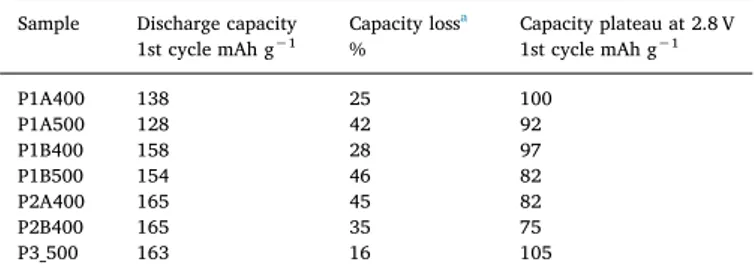
Table 1
Electrochemical performances of Li4Mn5O12powder samples tested with carbon
and binder.
Sample Discharge capacity
1st cycle mAh g−1 Capacity loss a
% Capacity plateau at 2.8 V1st cycle mAh g−1
P1A400 138 25 100 P1A500 128 42 92 P1B400 158 28 97 P1B500 154 46 82 P2A400 165 45 82 P2B400 165 35 75 P3_500 163 16 105
respectively. Similar trends were observed with thermal treatment at 500 °C (samples P1B500 and P1A500). The shorter discharge plateau observed at 2.8 V vs. Li/Li+(Table 1) and the slight shift of the plateau towards lower voltages for samples treated at 500 °C and/or with ad-justment of pH before mixing with precursors (Fig. 3a and b, samples P1B500 and P1A500) are consistent with the observations on CVs, i.e. a broader peak linked to poorer electrode kinetics compared to P1A400. The electrochemical performances of synthesis 2, which starts from nitrate precursor salts instead of acetate salts, and for which the pH is adjusted at 6, are shown inFig. 3c andTable 1. Adjustment of the pH before mixing leads to better capacity retention after 20 cycles, i.e. 64% for P2B400 compared to 55% for P2A400. Synthesis 2 exhibits slightly higher initial capacities than synthesis 1, 165 mAh g−1and 158 mAh g−1being the highest capacities observed for both syntheses respec-tively. A measured discharge capacity slightly higher than the theore-tical value (163 mAh g−1) is linked to the error on weight measurement of the cathode. The capacity of the discharge plateau is lower (82 mAh g−1) for synthesis 2 compared to synthesis 1 (100 mAh g−1) and the voltage of the plateau is also lower (2.8 V vs. Li/Li+for synthesis 2 compared to 2.85 V vs. Li/Li+for synthesis 1) indicating poorer elec-trode kinetics for synthesis 2 as already shown by the corresponding CVs (Fig. 2c). This is counter-intuitive since particles observed in P2A400 and P2B400 are smaller than those observed in samples pre-pared by method 1, which should have led to increased performances due to shorter diffusion length for lithium ion [37]. Thus, the poorer electrochemical results of synthesis 2 could be related to the more compact arrangement of particles in the corresponding powders (see Fig. 1), reducing the interaction between the active material and the electrolyte and leaving less space between particles for easy diffusion of lithium ions into the material [35].
Synthesis 3, with introduction ofL-lysine as alternative to citric acid,
shows the best electrochemical properties in charge-discharge mode with an initial discharge capacity of 163 mAh g−1, a discharge plateau capacity of 105 mAh g−1and a capacity fade of 16% after 20 cycles. This capacity fade is still high but it can be seen fromFig. 3d that most of the capacity loss (11%) takes place at cycle 2. After cycle 2, P3_500
shows good capacity retention compared to synthesis 1 and 2 for which the capacity fade is continuous during successive cycles. In the case of P3_500, a capacity over 130 mAh g−1is maintained after 20 cycles. The better electrochemical performances of synthesis 3 could be due to its particular nanoflake morphology, which could increase the contact area between electrolyte and active material, thus reducing Li+ diffusion paths as demonstrated with a similar morphology by Fu et al. [35].
The good electrochemical properties of P3_500 (acetate precursor salts and L-lysine as reactants) can be compared to electrochemical
performances of Li4Mn5O12 powders [13–18,35,38,39] and spinel-layered Li4Mn5O12.Li2MnO3material [34,40–42] from the literature in Table 2. All these materials were tested as composite positive electrode made of the active material, carbon as electrical conductor and a binder. For Li4Mn5O12material, the highest initial discharge capacity at low cycling rate (0.1–0.3 C) is 150–160 mAh g−1with a capacity fade of minimum 5% after 50 cycles [15]. The largest discharge plateau at 2.8 V vs. Li/Li+observed during initial discharge is 131 mAh g−1at a medium rate of 0.5 C [16]. Positive electrode materials with spinel-layered hybrid structure Li4Mn5O12/Li2MnO3[34,40–42] combine the advantages of the two phases, such as the excellent cyclic stability and high coulombic efficiency of the spinel phase (Li4Mn5O12), as well as the high discharge capacity and the outstanding structural stability of the layered phase (Li2MnO3) [43]. However, the increase of discharge capacity above 200 mAh g−1is at the expense of the capacity of the discharge plateau at 2.8 V vs. Li/Li+[34,41]. Thus, our material P3_500 shows respectable results compared to the literature, showing initial discharge capacity similar to the best ones observed for pure Li4Mn5O12 [16,35] but lower capacity retention and capacity plateau than the best materials found in the literature [15,16]. However, in the latter cases, the Li4Mn5O12powders were synthesized by solid state reaction and can therefore not be transposed to film deposition via a wet route.
Due to its good electrochemical properties, synthesis 3 (P3_500) withL-lysine and acetate salts as precursors was chosen for direct spray
coating of pure Li4Mn5O12films on stainless steel discs. The precursors’ solution for spray coating was first prepared with similar conditions as for synthesis of powder 3 with water as solvent (sample SC0.8W). As
Table 2
Comparison of electrochemical performances of Li4Mn5O12obtained with different synthesis methods.
Author Method Voltage range vs.
Li/Li+ V
Discharge capacity
1st cycleamAh g−1 Capacity loss b
% Capacity plateau at2.8 V 1st cycle mAh g−1
Thackeray 1992 [13] Solid state reaction 2.3–3.3 135 (0.5 mA cm−2) 7 (3) 112
Takada 1997 [14] Molten salt reaction 2.5–3.6 135 (0.3 mA cm−2) 26 (10) 117
Kim 1998 [38] Co-precipitation 2.3–3.3 153 (0.1 mA cm−2)
150 (0.5 mA cm−2) 1 (10)1 (40) 132117
Tian 2007 [39] Molten salt reaction 2.3–3.3 154 (0.2 C) 9 (30) 110
Choi 2007 [15] Solid state reaction 2.4–3.3 148 (0.2 C) (Li4Mn5O12)
160 (0.2 C) (Li4Mn5O12-ɳFɳ) 5 (50)3 (50) 130133 Jiang 2010 [16] Spray-dried assisted solid state reaction 2.4–3.7 159 (0.5 C)
130 (1 C) 18 (50)15 (50) 131
Ivanova 2013 [17] Solid state reaction 1.6–3.6 182 (0.05 C)
90 (0.2 C) 60 (1 C)
29 (20) 88
Fu 2014 [35] Porous Li4Mn5O12by solution reaction 2–3.5 161 (0.3 C) 135 (0.6 C) 110 (1.2 C) 100 (3 C)
24 (50) 122
Zhang 2015 [18] Solid state reaction 2.3–3.3 140 (0.2 C) 7 (30) 122
Cao 2011 [34] Tubular 0.5Li2MnO3.0.5Li4Mn5O12self-templating method 2–4.8 200 (0.1 C)
155 (0.5 C) 5 (15)26 (15) 58 Li 2011 [39] Core-shell Li2MnO3.Li4Mn5O12solid state reaction 2–4 136 (0.06 C) 6 (50) 63 Kim 2014 [40] mesoporous Li2MnO3.Li4Mn5O12inverse micelle method 2–4.8 270 (0.1 C) 17 (25) 48 Liu 2016 [41] Li2MnO3.Li4Mn5O12solid state reaction 2.3–3.3 135 (0.2 C)
110 (0.5 C) 90 (1 C) 15 (50) 5 (50) 0 (50) 119
a The number into brackets indicates the rate at which the initial discharge capacity was measured. b The number into brackets indicates the number of cycles after which the capacity loss was observed.
the wettability of the substrate with aqueous precursor solution was bad, films were also prepared by spray coating of precursors dissolved in methanol (SC0.8 M and SC2M); this modification led to significantly better adhesion of the film onto the stainless steel substrate. The final thermal treatment of the thin films was performed at 400 °C and not at 500 °C as for the corresponding powder because 400 °C generally leads to better electrochemical properties than 500 °C (see comparison for synthesis 1 and [18]).
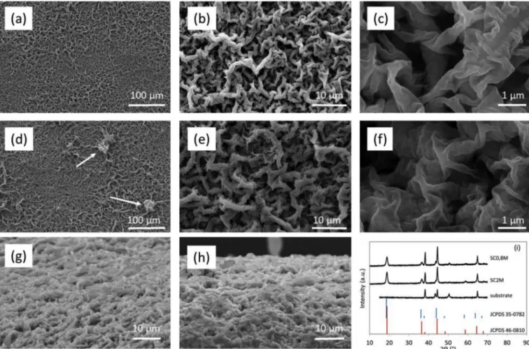
SEM images of Li4Mn5O12films prepared by spray coating of me-thanolic precursors' solutions are shown in Fig. 4. No SEM images of Li4Mn5O12films prepared from aqueous precursors' solutions are pre-sented because the electrochemical properties of these films are poor, as will be demonstrated hereafter. The microstructure is quite similar for both thicknesses (Fig. 4b, c and g for SC0.8 M andFig. 4e, f and h for SC2M) and displays an open porosity, which promotes the migration of lithium ions inside the lithium manganese oxide matrix through in-creased wetting of the film by the liquid electrolyte. The difference between the two films lies in the clusters of material (shown by arrows), which are only present for thicker films (Fig. 4d).Fig. 4i shows the XRD patterns of Li4Mn5O12films prepared from methanolic precursors’ so-lutions. The XRD pattern of the bare substrate is also presented as its diffraction peaks interfere with those of lithium manganese oxide. The diffraction peaks of the films are consistent with the formation of Li4Mn5O12.
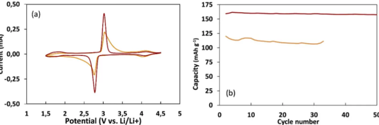
Fig. 5a shows the CV curves for SC0.8W and SC0.8 M. For both films, no redox peaks are observed within the 3.5–4.3 V vs. Li/Li+ re-gion, pointing to the absence of LiMn2O4in the films. This result shows that it is possible to avoid the formation of LiMn2O4species by the direct deposition of the precursors as electrode material. The two redox
peaks of Li4Mn5O12are sharper and more intense for the film processed using a methanol solution, indicating better electrochemical kinetics. The cycling performances at 0.5 C are much better for SC0.8 M than for SC0.8W, with a discharge capacity of 160 and 120 mAh g−1, respec-tively (Fig. 5b). Thus, films with higher loadings were prepared by spray coating of methanolic precursors’ solutions.
Fig. 6shows the comparison of the CVs obtained with the powder sample P3_500 in composite electrode configuration (mixture with carbon and binder) and with the two Li4Mn5O12 films, SC0.8 M and SC2M. In this figure, the current is expressed in A per gram of lithium manganese oxide as the active mass is different for all samples. No redox peaks are observed within the 4 V region (i.e. 3.5–4.3 V vs. Li/ Li+) for both films, proving the absence of LiMn2O4in the films. The presence of LiMn2O4in the powder sample, P3_500, could possibly be due to the reduction of part of the Mn4+to Mn3+owing to the addition of carbon for electrode processing. The pair of reversible redox peaks of Li4Mn5O12 around 3 V vs. Li/Li+ is sharper for films, especially for SC0.8 M, suggesting good electrochemical kinetics for this sample. The redox potential in charge process (oxidation) is shifted towards lower value for SC0.8 M (3.05 V vs. Li/Li+) compared to P3_500 (3.09 vs. Li/ Li+) and the redox potential in discharge process is shifted towards higher value (2.78 V vs. Li/Li+, to be compared to 2.70 vs. Li/Li+for P3_500), pointing to lower overvoltage values and thus better cycling efficiency. The diffusion path for lithium ions is longer in thicker films of active materials (SC2M). Thus, broader redox peaks due to the slower insertion and extraction of lithium ion are observed in cyclic voltam-mograms.
The Li4Mn5O12 films deposited by spray coating were tested in charge-discharge mode at different rates from 0.1 C to 2 C.Fig. 7shows
Fig. 4. Top view SEM micrographs of Li4Mn5O12films prepared by spray coating of methanolic precursors' solutions: (a, b and c) SC0.8 M and (d, e and f) SC2M. Side
view SEM images of SC0.8 M film (g) and SC2M film (h). XRD patterns of Li4Mn5O12film samples and stainless steel substrate (i). Standard XRD patterns of
the successive charge and discharge curves for the two films prepared with methanol and loadings of 0.8 or 2 mg cm−2. Specific capacities (i.e. per electrode surface area) of respectively 132 (SC0.8 M) and 330 μAh cm−2(SC2M) are obtained during first discharge at a rate of 0.1 C; at a rate of 2C, capacities still reach 120 (SC0.8 M) and 275 μAh cm−2(SC2M) during first discharge.
Fig. 8a and b show the rate capability for the two loadings. The electrochemical properties of the films are excellent at a rate of 0.1 C whatever the Li4Mn5O12loading (Fig. 7a and b,Fig. 8andTable 3). At medium rates of 0.25 C and 0.5 C, the excellent performances are maintained for SC0.8 M: the capacity is close to the theoretical capacity and the cyclability is very good. The capacity fade is higher for SC2M, reaching 17% vs. 5% only for SC0.8 M after 100 cycles (Table 3). The difference of capacity fade between the two loadings becomes more acute with faster cycling rates of 1C and 2 C as shown onFig. 8. The capacity fade reaches 37% for SC2M vs. 10% for SC0.8 M after 50 cycles (Table 3). The initial capacity is affected by the cycling rate and its decrease is more intense for a higher Li4Mn5O12loading. An excellent initial capacity of nearly 150 mAh g−1 is however reachable for SC0.8 M at a high rate of 2 C. The loss of capacity at 2 C is not due to a degradation of the electrode material: indeed, cycling at lower rates subsequent to a cycling period at 2C leads to capacity values similar to those obtained if the battery had undergone the same number of cycles at 0.5 C or 1C only (Fig. 8a and b).
The length of the discharge capacity plateau around 2.8 V vs. Li/Li+ is also influenced by the cycling rate and, again, its shortening with rate is more pronounced for SC2M compared to SC0.8 M (Table 3). For
example, the capacity of the plateau is 115 mAh g−1for SC0.8 M vs. 100 mAh g−1for SC2M at 0.5 C. For both loadings, the oxidation pla-teau shifts to higher potential values while the reduction plapla-teau shifts gradually to lower potential values as the cycling rate increases. Thus, the potential difference between charge and discharge plateaus, ΔV, is increased, which leads to the appearance of electrical polarization phenomenon.
The cyclic voltammograms recorded after the 150 rate performance cycles are very similar to those obtained with fresh batteries for both loadings (Fig. 8c and d). The only differences are a slight peak shift towards higher oxidation potential in charge process and a slightly higher peak in the 4 V region (i.e. 3.5–4.3 V vs. Li/Li+) for both films. This indicates that the films are not altered by the 150 cycles of charge and discharge at rates between 0.1 and 2 C.
The mechanism proposed for the energy storage in Li4Mn5O12 electrode, which is based on the concept of intercalation of Li+ions [44], can be described as follows:
Li4Mn5O12+ xLi++xe− Li4+xMn5O12 (1) During the charge process, Li+ions present in spinel Li4+xMn5O12 material deinsert, leading to the formation of Li4Mn5O12. As a con-sequence, many Li vacant sites are formed in the electrode material. During the discharge process, Li+ions can be reinserted into the vacant sites, following equation(1). Li4Mn5O12can accommodate 3 Li+ions to form Li7Mn5O12[45]. Increasing the charge-discharge rate has a direct impact on the diffusion of Li+ions into the Li4Mn5O12matrix. In other words, when the cycling rate is faster, Li+ions reach only the outer surface of the electrode and not the interior of Li4Mn5O12film matrix. This reduces the available capacity from 165 to 149 mAh g−1 for SC0.8 M and from 165 to 138 mAh g−1for SC2M when the cycling rate is increased from 0.1 to 2 C. Hence, it is clear that when the current density is higher, the participation of the Li4Mn5O12electrode is limited to a certain film depth, leaving the inner of the film inactive. This phenomenon leads to a lower specific capacity, especially for a higher Li4Mn5O12loading. The shortening of the discharge and charge pla-teaus are due to the increasing cell polarization caused by lithium dif-fusion resistance with increasing cycling rate. The faster capacity fade and shorter plateaus observed for SC2M indicates that the film thick-ness plays an important role in the electrochemical performances as the thickness of SC2M is 15 μm compared to 8 μm for SC0.8. Moreover, the lithium insertion/deinsertion requires longer time to reach equilibrium for thicker films as they contain a larger amount of material [46,47]. So, an effort still has to be done on the improvement of the rate cap-ability of Li4Mn5O12films for loadings higher than 1 mg cm−2.
Despite the above-mentioned limitation, a specific capacity of 330 μAh cm−2 is reached with a loading of 2 mg cm−2, which is sig-nificantly higher than the loadings and specific capacities reported for lithium manganese oxide films in the literature [25,26,28,48,49]. In
Fig. 6. Cyclic voltammograms (second cycle) at a scan rate of 0.1 mV s−1for
spray coated films with different loadings, SC0.8 M ( ) and SC2M ( ), and corresponding powder sample P3_500 ( ). The current is expressed in A per gram of lithium manganese oxide to allow comparison.
Fig. 5. (a) Cyclic voltammograms (second cycle) at a scan rate of 0.1 mV s−1and (b) capacity retention (0.5 C rate) of the films prepared by spray coating of aqueous
fact, the present study constitutes the second report on thin films of Li4Mn5O12; the first study deals with spin-coated Li4Mn5O12film using a Li1.5Al0.5Ge1.5(PO4)3(LAGP) solid electrolyte [48] and not a liquid electrolyte as in this study, so the results are not comparable. Former published literature on lithium manganese oxide films to which we can compare our results deals with thin films of LiMn2O4, leading to lower specific capacity values. As an example, Striebel et al. [49] prepared LiMn2O4thin films by pulsed laser deposition with thicknesses from 0.2 to 1.5 μm. The corresponding discharge capacities evolve from 7 to 84 μAh cm−2at a current rate of 10 μA cm−2. Since the theoretical capa-city of LiMn2O4equals 148 mAh g−1, this current corresponds to 0.8 C and 0.1 C for the 0.2 μm and 1.5 μm thick films, respectively. The LiMn2O4thin films, 0.3 μm thick, prepared by pulsed laser deposition by Tang et al. [25] develop a specific capacity of 14 μAh cm−2with a current density of 50 μA cm−2(2.5 C), a value calculated assuming that the films are not porous and display the theoretical density of LiMn2O4 (4.3 g cm−3). Yim et al. [26] reported on Sn-substituted LiMn
2O4thin films prepared by pulsed laser deposition showing a specific capacity of 67 μAh cm−2 at a current rate of ∼4 C. Rho et al. [28] prepared LiMn2O4 thin films by PVP-assisted (Poly(vinylpyrrolidone)) sol-gel coating method (spin coating) with thickness around 1 μm. The specific
discharge capacity was 60 μAh cm−2at a current density of 50 μA cm−2 (0.8 C). As already pointed out, these values are much lower than those reported in the present study, which highlights the interest of the method to manufacture efficient lithium manganese oxide films for microbatteries.
4. Conclusions
We developed an innovative rapid method to prepare pure Li4Mn5O12 films with high loading, up to 2 mg cm−2, and excellent electrochemical properties as Li-ion positive electrode. Films were de-posited on stainless steel current collectors using spray coating of sol-gel derived precursors’ solutions. This method allows preparing elec-trodes without any binder or additive.
First, we carried out a screening of Li4Mn5O12powders synthesis pathways via sol-gel process, easily applicable to spray coating of films, in order to select the synthesis method leading to the best electro-chemical properties. These syntheses used either citric acid orL-lysine
as complexing and combusting agent. These Li4Mn5O12powders were tested as composite electrodes made of the active material, carbon as electrical conductor additive and PVDF as a binder. Due to their
Fig. 7. Charge-discharge curves at various C-rates (0.1 C, 0.5C and 2C) for films with different loadings: SC0.8 M with 0.8 mg cm−2(a, c and e) and SC2M with
nanoflake structure, and thus to the higher surface area, Li4Mn5O12 prepared with L-lysine displays an increased number of conducting
pathways at the electrode/electrolyte interface; this explains the better electrochemical performances of this synthesis method.
In a second step, theL-lysine synthesis method was used to deposit
pure Li4Mn5O12film with various thickness by spray coating on stain-less steel discs. Films with excellent performances at high cycling rates and good cyclability could be obtained. For a 0.8 mg cm−2loading, an initial discharge capacity of 162 mAh g−1is achievable at a current rate of 0.5 C (assuming that the active material displays the theoretical ca-pacity of 163 mAh g−1) with a capacity fade of 5% after 100 cycles. At a rate of 2 C, the initial capacity is still 149 mAh g−1with a capacity fade of 11% after 100 cycles. For high Li4Mn5O12 film loadings (2 mg cm−2), the active material is however not completely utilized at high rates and redox reactions are difficult for the very inner lattice of Li4Mn5O12matrix, leading to a lower capacity with increasing cycling rate (138 mAh g−1at a rate of 2 C). However, the sol-gel process withL -lysine may be a basic key technology for development of microscale rechargeable lithium batteries from Li4Mn5O12 leading to high
capacities of 330 μAh cm−2compared to LiMn2O4film from the lit-erature.
Acknowledgements
This work was supported by the Walloon Region (Phosphagel pro-ject, grant n°0917013), the EU H2020 ECSEL program (ENSO propro-ject, grant n°692482) and by Prayon S.A. through private funding.
References
[1] J.M. Tarascon, M. Armand, Nature 414 (2001) 359.
[2] V. Etacheri, R. Marom, R. Elazari, G. Salitra, D. Aurbach, Energy Environ. Sci. 4 (2011) 3243.
[3] N. Nitta, F. Wu, J. TaeLee, G. Yushin, Mater. Today 18 (2015) 252. [4] A. Manthiram, ACS Cent. Sci. 3 (2017) 1063.
[5] M.M. Thackeray, J. Electrochem. Soc. 142 (1995) 2558.
[6] P.G. Bruce, B. Scrosati, J.M. Tarascon, Angew. Chem. Int. Ed. 47 (2008) 2930. [7] F. Schipper, E.M. Erickson, C. Erk, J.Y. Shin, F.F. Chesneau, D. Aurbach, J.
Electrochem. Soc. 164 (2017) A6220.
[8] Y.J. Park, J.G. Kim, M.K. Kim, Solid State Ionics 130 (2000) 203.
Fig. 8. Rate performance and cyclability for films with various thickness: (a) SC0.8 M and (b) SC2M. Cyclic voltammograms (second cycle) at a scan rate of
0.1 mV s−1for films before (-) and after (…) the 150 rate performance cycles: (c) SC0.8 M and (d) SC2M.
Table 3
Electrochemical performances of pure Li4Mn5O12films.
Sample Rate
C Discharge capacity1st cycle mAh g−1 Capacity loss% Capacity plateau at2.8 V
1st cycle mAh g−1 Cycle number 10 20 50 100 SC0.8 M 0.1 165 3 5 9 132 SC0.8 M 0.5 162 1 2 2 5 115 SC0.8 M 2.0 149 7 9 10 11 90 SC2M 0.1 165 2 2 120 SC2M 0.5 165 5 6 11 17 100 SC2M 2.0 138 20 30 37 70
[9] H. Xia, Z. Luo, J. Xie, Prog. Nat. Sci-Mater. 22 (2012) 572.
[10] J.S. Kim, K. Kim, W. Cho, W.H. Shin, R. Kanno, J.W. Choi, Nano Lett. 12 (2012) 6358.
[11] T. Ohzuku, M. Kitagawa, T. Hirayi, J. Electrochem. Soc. 137 (1990) 769. [12] E. Levi, M.D. Levi, G. Salitra, Solid State Ionics 126 (1999) 109.
[13] M.M. Thackeray, A. De Kock, M.H. Rossouw, J. Electrochem. Soc. 139 (1992) 363. [14] T. Takada, H. Hayakawa, E. Akiba, F. Izumi, B.C. Chakoumakos, J. Power Sources
68 (1997) 613.
[15] W. Choi, A. Manthiram, Solid State Ionics 178 (2007) 1541.
[16] Y.P. Jiang, J. Xie, G.S. Cao, X.B. Zhao, Electrochim. Acta 56 (2010) 412. [17] S. Ivanova, E. Zhecheva, D. Nithianova, M. Mladenov, R. Stoyanova, J. Alloy. Comp.
561 (2013) 252.
[18] J. Zhang, W. Wang, Y. Li, D.Y.W. Yu, Electrochim. Acta 185 (2015) 76. [19] M.M. Thackeray, M.F. Mansuetto, C.S. Johnson, J. Solid State Chem. 125 (1996)
274.
[20] C.H. Lu, S.W. Lin, J. Power Sources 97–98 (2001) 458. [21] K. Matsuda, I. Taniguchi, J. Power Sources 132 (2004) 156.
[22] Y.H. Rho, K. Kanamura, T. Umegaki, J. Electrochem. Soc. 150 (2003) A107. [23] K.F. Chiu, H.C. Lin, K.M. Lin, C.H. Tsai, J. Electrochem. Soc. 152 (2005) A2058. [24] B.J. Hwang, C.Y. Wang, M.Y. Cheng, R. Santhanam, J. Phys. Chem. C 113 (2009)
11373.
[25] S.B. Tang, H. Xia, M.O. Lai, L. Lu, J. Alloy. Comp. 449 (2008) 322. [26] H. Yim, D.W. Shin, J.W. Choi, J. Kor. Phys. Soc. 68 (2016) 41.
[27] J.L. Shui, G.S. Jiang, S. Xie, C.H. Chen, Electrochim. Acta 49 (2004) 2209. [28] Y.H. Rho, K. Dokko, K. Kanamura, J. Power Sources 157 (2006) 471. [29] Y.H. Ikuhara, X. Gao, R. Huang, C.A.J. Fisher, A. Kuwabara, H. Moriwake,
K. Kohama, J. Phys. Chem. C 118 (2014) 19540.
[30] Y.J. Hao, Y.Y. Wang, Q.Y. Lai, Y. Zhao, L.M. Chen, X.Y. Ji, J. Solid State Electrochem. 13 (2009) 905.
[31] Y. Zhao, Q.Y. Lai, H. Zeng, Y.J. Hao, Z. Lin, Ionics 19 (2013) 1483. [32] B.J. Hwang, R. Santhanam, D.G. Liu, J. Power Sources 101 (2001) 86. [33] M.M. Thackeray, C.S. Johnson, S.H. Kang, L. Trahey, J.T. Vaughey, U.S. Patent 8,
313,721, 2010.
[34] J. Cao, J. Xie, G. Cao, T. Zhu, X. Zhao, S. Zhang, Electrochim. Acta 111 (2011) 447. [35] Y. Fu, H. Jiang, Y. Hu, L. Zhang, C. Li, J. Power Sources 261 (2014) 306. [36] Y. Chen, K. Xie, Y. Pan, C. Zheng, J. Power Sources 196 (2011) 6493. [37] M.A. Kiani, M.F. Mousavi, M.S.T. Rahmanifar, Int. J. Electrochem. Sci. 6 (2011)
2581.
[38] J. Kim, A. Manthiram, J. Electrochem. Soc. 145 (1998) L53. [39] Y. Tian, D. Chen, X. Jiao, Y. Duan, Chem. Commun. (2007) 2072. [40] Y. Li, Y. Makita, Z. Lin, S. Lin, N. Nagaoka, X. Yang, Solid State Ionics 196
(2011) 34.
[41] S.J. Kim, Y.W. Lee, B.M. Hwang, S.B. Kim, W.S. Kim, G. Cao, K.W. Park, RSC Adv. 4 (2014) 11598.
[42] G. Liu, S. Zhang, S. Wang, Int. J. Electrochem. Sci. 11 (2016) 5792.
[43] C. Liu, Z. Wang, C. Shi, E. Liu, C. He, N. Zhao, ACS Appl. Mater. Interfaces 6 (2014) 8363.
[44] A. Brett, J. Deborah, J. Roziere, J. Burns, R. Gary, Chem. Mater. 7 (1995) 2151. [45] E. Ferg, R.J. Gummow, A. de Kock, M.M. Thackeray, J. Electrochem. Soc. 141
(1994) L147.
[46] Z. Quan, S. Ohguchi, M. Kawase, H. Tanimura, N. Sonoyama, J. Power Sources 244 (2013) 375.
[47] A. Rougier, K.A. Striebel, S.J. Wen, E.J. Cairns, J. Electrochem. Soc. 145 (1998) 2975.
[48] M. Kotobuki, Adv. Chem. Sci. 2 (2013) 29.
[49] K.A. Striebel, C.Z. Deng, S.J. Wen, E.J. Cairns, J. Electrochem. Soc. 143 (1996) 1821.