The development and applications of a ground-based
fiber nulling coronagraph
Stefan Martin, Eugene Serabyn, Kurt Liewer, Frank Loya, Bertrand Mennesson*, Charles Hanot**
and Dimitri Mawet.
Jet Propulsion Laboratory, California Institute of Technology,
4800 Oak Grove Drive, Pasadena, CA, USA 91109. *Formerly at JPL, **AEOS, University of
Liege, Belgium.
ABSTRACT
A rotating nulling coronagraph has been built for use on ground-based telescopes. The system is based on the concept of sub-aperturing the pupil of the telescope with two elliptical apertures and combining the resulting two input beams on a single-mode fiber. By a relative π phase shift of the beams, the starlight can be nulled and a relatively faint companion
star can be detected. Rotation of the aperture mask on the telescope pupil results in a signal similar to that expected from a space-borne telescope system such as the proposed TPF/Darwin interferometer. The design of the nulling coronagraph and the ancillary systems that are needed, such as the fringe tracker, are described and the potential for observations on telescopes such as the Palomar 200” is discussed. Results of a nulling experiment using a single mode fiber as a beam combiner for broadband light between 1.50 µm and 1.80 µm are shown.
Keywords: Nulling interferometry, nulling coronagraphy, exo-planets.
1. INTRODUCTION
Large nulling interferometer designs proposed by ESA[1] and by NASA[2] for exo-planet characterization in the
mid-infrared utilize several telescope apertures formed by an array of spacecraft. For example, the recent Darwin proposal to ESA proposed an array of four telescopes disposed in an X-formation with a beam-combining spacecraft at the center. While such telescopes would have extraordinary performance, simpler and much less costly designs can also utilize some of the technology to make productive instruments for astronomical studies. In a nulling interferometer, light from a target star is dimmed by destructive interference. This increases the relative brightness of any off axis objects, such as planets or companion binary stars. In the infrared, together with local zodiacal light and other sources of thermal noise, a target system will radiate significant exozodiacal light, so that this extraneous light will be greater than the nulled starlight. To detect the faint companion object against this background, the telescope array will be rotated so as to sweep interference fringes across the object, thus modulating its signal. To do this with an array of large telescopes is a significant challenge, but the same or similar techniques can be employed on a monolithic telescope either on space or ground-based platforms. Once a single telescope structure is involved, the design challenges become more tractable and this opens the door to a low-cost instrument that can be attached to existing telescope facilities. This approach allows the inexpensive application and testing of multi-aperture techniques as well as providing science results.
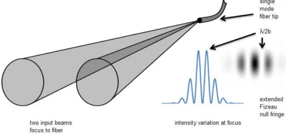
Placing two apertures over a single telescope entrance pupil and achromatically shifting the phase of the starlight in one aperture by exactly π produces a laterally extended (Fizeau) fringe at the focus. At the fringe center, the starlight is
nulled, while away from the center it is alternately constructively and destructively interfered, see Figure 1. Placing a single mode fiber at the focus so that both apertures fall symmetrically within its field of view produces a null in the starlight, while off-axis sources will produce slightly laterally shifted fringes that will, in general, not be nulled. Since this type of interferometer uses neither multiple independent apertures nor beamsplitters it has been called a nulling coronagraph[3], a term which is intended to indicate its relatively simple, single telescope-based design. By combining
the incoming beams on a single fiber tip[5][6], the complex beamsplitter and compensator plate designs found in standard
single mode fiber tip J2 b
4
II,
extended Fizeau null ftingetwo input beams intensity variation at focus
focus to fiber
to retain high spatial resolution on the target the wavelength is also reduced. A further simplification over the TPF-Emma X-array design, for example, is to use only two instead of four apertures. This creates a simpler fringe pattern on the sky, eliminating the ability to perform phase chopping, a background reduction technique; at the shorter operating wavelength the zodiacal and instrument thermal backgrounds are reduced so that the need for the background reduction is removed. Another important property of phase chopping is to break the symmetry of the output reconstructed signal so that the location of the detected object is restricted to one side of the star. Without this, the reconstructed maps have mirror symmetry across the star.
Figure 1: Principle of a fiber nulling coronagraph. Two incoming beams of light from the source are focused onto a single mode fiber. At the focus, Fizeau fringes are formed with an intensity variation in space as shown on the right. If the electric field of one of the beams is inverted, the central fringe is nulled (inverted). The telescope is pointed at the star which is nulled and an off-axis object at an angle λ/2b will be constructively interfered.
1.1 Fiber nulling coronagraph experiments
Such a nulling coronagraph has been demonstrated in the laboratory. Using laser light at 633 nm wavelength, null depths of almost 1 million to one have been achieved[6] and with a similar test setup (top part of Figure 2) using
broadband light of 1.50 to 1.80 µm (full width, half maximum), null depths of 14,000:1 were achieved as shown in the
lower part of Figure 2. The graph was made by smoothing the output from the nuller with a time constant of 10 s. In this broadband experiment the output of a tungsten-halogen lamp was coupled to a single mode fiber and introduced into the nuller. After collimation of the expanding output beam by a parabolic mirror, a pair of circular apertures intersected the beam to produce two beams of light. Two slightly wedged plates approximately 1 mm thick made of CaF2 (known as
phase-plates) were inserted into the collimated beams with differential thicknesses chosen to approximately achromatize the null across the passband. Twin piezoelectrically controlled mirrors reflected the light to a refocusing parabolic mirror and thence to a single mode output fiber. The twin mirrors allowed control of the beam tip/tilt and piston, and by applying piston control in opposite directions, the optical path difference between the beams could be controlled. The null was maintained using a lock-in technique to continuously adjust the phase difference between the two input apertures to achieve the deepest null. Also, intensity balance was manually adjusted by fine control of the apertures’ positions using a microstepping motor. Since the output beam from the fiber has a near-Gaussian profile, small lateral adjustments of the aperture mask affect the relative intensity of the two output beams. Tip/tilt mirror angles were also maintained using the lock-in technique to achieve stable nulls. These experiments showed that high levels of performance near the best achieved using other types of nulling interferometer[7],[8],[9] are possible.
1.2 Inner working angle
The inner working angle is the nominal smallest angular separation at which an object can be distinguished from the star is the angle αλ/2b where λ is the wavelength, b the baseline and α a constant of proportionality. The baseline is
measured between aperture centers. The angle is the location of the first constructive fringe when the null fringe is on the star. As the fringe pattern is rotated around the star the target object’s transmission through the optics will vary and
Phase [ plates
Fiber coupling from thermal source
Twin tip/ti Its
with piston 100 — 1 0 10 a a) 0 Z io 1o4 0 100 200 300 400 500 Time (s)
for close-in objects the peak transmission will never reach the maximum encountered at λ/2b. The constant of
proportionality α for the inner working angle may therefore be chosen to be less than one and sometimes as low as 0.5.
Compared with a conventional coronagraph, in which the target star is occulted using a mask, having typically an inner working angle of a few λ/D where D is the telescope diameter, the nulling coronagraph promises significantly higher
angular resolution.
Figure 2: Top: layout of the fiber nuller used for broadband nulling tests. Bottom: broadband null with 18% bandwidth centered at 1.65 um from the fiber nuller breadboard at JPL. Between ~ 40 s and ~ 310 s the null is better than 10-4. At
the right of the plot, the constructive fringe peak is shown.
2. DESIGN CONCEPT
To test this concept on the sky, a fiber nulling coronagraph has been built and is initially to be deployed on the Palomar Observatory’s 200” telescope. Located following the adaptive optics (AO) bench, the instrument takes advantage of the phase corrections applied across the telescope aperture which are expected to leave a residual 150 to 200 nm rms optical path difference between the apertures.
Class block
Compressed pupil
Pupil
0 000
Figure 3: On the left, the white area represents the telescope entrance pupil at Palomar and the dark area the large
obscuration of the secondary mirror. Telescope secondary mirror spiders are not shown. Center, the aperture with two circular sub-apertures of near maximum size. Right, the aperture with two elliptical sub-apertures of twice the area.
2.1 Efficiency
Fiber beam combiners generally have lower efficiency than conventional combiners because they fail to fill the field of view of the fiber. In a conventional beamcombiner built using beamsplitters, the two incoming beams are coaxial and can be well matched to the numerical aperture of a single mode fiber. (A fiber is used in this instance to improve the wavefront quality and decrease the sensitivity of the null to misalignments.) However, in the fiber beamcombiner, the input apertures do not fill the fiber’s field of view. This can be remedied to some extent by increasing the aperture sizes as much as possible. Figure 3 shows, on the left, the input pupil of the Palomar 200” telescope with the central obscuration in black. Center and right, two circular apertures and two elliptical apertures are placed on the pupil. Table 1 shows the relative aperture areas compared with an unobscured circular aperture. Modeling a standard single mode fiber of numerical aperture 0.13 at the focus of an appropriate lens, we found the coupling efficiencies at the design wavelength shown in the table, improving approximately with the square of the aperture area.
Table 1: Relative areas and coupling efficiencies to a single mode fiber for various apertures.
Aperture type Unobscured
“top hat” obscuration Central circular apertures Two separated elliptical apertures Two separated elliptical apertures Two densified
Relative area 100% 82% 19% 38% 38%
Coupling
efficiency 81% 52% 3% 10% 52%
Figure 4: Compression of the entrance pupil using a prism.
Finally, by ‘densifying’ the elliptical apertures so that they fill the fiber’s mode field more fully, the aperture configuration shown on the right in Figure 4 can be produced. The coupling efficiency is up to 52% with the relative area of 38%, as shown in the table. This densification could be achieved by inserting some additional optics in the
phase Apertures plates
.
piston mirror telescope Input fromgle
mode fibercollimated beam as illustrated in the figure. This approach produces a small chromatic variation of the densification which can be avoided in more complex designs using mirrors.
At the focus the focal spot dimensions will have the scale 1/a0 where a0 is one of the diameters of the entrance ellipse.
The fringe spacing at the focus will have the scale 1/(D- a0) where Dis the telescope diameter. Therefore, for the
geometry shown on the right in Figure 3, the field of view will contain approximately two fringes. To obtain a wider field of view, the elliptical aperture diameter should be decreased relative to the entrance pupil. Pupil densification then becomes more important to maintain the coupling efficiency.
2.2 Rotation
To rotate the fringe system either the apertures can be rotated, the telescope can be rotated or the input pupil can be rotated using a K-mirror arrangement. Telescope rotation is an option; for a spacecraft a simple spin around the optical axis is possible. Such an approach would help to maintain null stability since the parts of the optical system that the beams touch will remain the same. For a ground-based telescope, the focal plane optical system sometimes may be rotated; such is the case at Palomar. A simpler scheme would be rotation of the sub-apertures but this requires that the nulling optics can accept the apertures at all angles; this is not the case in the design described below in which only a limited rotation is possible because of the fixed phase control mirrors. Rotation of the input pupil using a K-mirror or Dove prism allows the apertures and downstream optics to remain fixed but adds some complication to the alignment control. If the K-mirror’s rotation axis is off-center it will cause the beam axis to describe a cylinder and if the axis is tilted the beam will describe a cone. Also the K-mirror’s components must be accurately assembled to avoid similar internally produced effects.
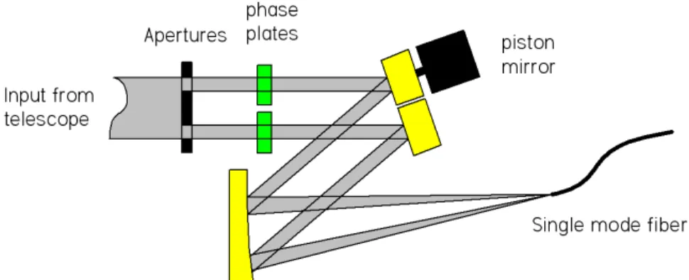
2.3 Phase shifting
Figure 5 shows a simplified layout of our fiber nulling coronagraph. The input beam is apertured to create two beams, which pass through phase plates, reflect from a pair of mirrors and are then focused onto a single mode fiber. One of the mirrors has adjustable piston, so that the distance traveled by one of the two beams can be varied. The phase plates are made of one or more glasses and have slightly different thickness in the two beams. To achieve an achromatic null across the passband, path differences would be set up between the beams using different air paths and different types and thicknesses of glass. If the bandwidth is not large, and the null depth requirement not deep however, a simple air path difference would suffice. For example over the passband 2.0 to 2.3 µm, a mean null depth of ~300 is achievable using
only an air path difference.
Figure 5: Simplified layout of the fiber coronagraph
3. IMPLEMENTATION
The fiber nulling coronagraph built for Palomar has to fit on a section of optical bench adjacent to the adaptive optics (AO) system. The AO system corrects pointing and wavefront error across the main pupil, leaving residual errors such as non-common path pointing drifts to be corrected on the fiber nuller bench. Wavelengths from the target longer than about 1 µm are available at the output of the AO bench. On the coronagraph bench, nulling is performed at Ks-band
Fiber Nuller breadboard J-band quad cells: pointing H-band M Optical fringe M alignment tracker camera Detectors
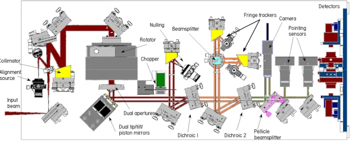
Figure 6: General layout of the fiber nuller. 3.1 General layout
Referring to Figure 6, light from the star enters the telescope, passes through the AO bench and then enters the fiber nuller. After beam steering at the input matching stage it is collimated and passed through a pupil rotator to a mask which produces two elliptical beams. Following the mask, piezoelectrically controlled mirrors are used to control the relative phase and pointing of the beams. K-band light is then separated using a dichroic beamsplitter and directed through a chopper to the nulling fiber. Similarly H-band light is separated from the remaining beam and directed to a fringe tracking system. The remaining light is shared between an alignment camera used during set-up and a set of quad cells used for dynamic pointing control when observing.
Figure 7: The fiber nuller breadboard.
Figure 7 shows the implemented nulling breadboard. A converging beam from the AO bench enters the instrument at the lower left and is collimated and passed through the rotator to the dual apertures which mask out two elliptical beams. The rotator may have nothing inside, a dove prism or a K-mirror. The K-mirror is the ideal solution but at the time of writing is still in fabrication. The dove prism can be procured off the shelf but has some performance drawbacks in that standard glasses are absorbtive above the 2 µm in wavelength so that the throughput is only around 25%. Also the prism
introduces some lateral shear across the spectrum so that at certain rotation angles, some of the wavelengths being used may be partially vignetted. Next, the beams are reflected from the dual tip/tilt/piston mirrors which control the pointing and relative phase of the beams. At the following optic, dichroic beamsplitter #1, the K-band light is reflected and directed towards the nulling fiber parabola where it is focused onto a single mode fiber of the fluoride glass type. The shorter wavelength radiation passes through dichroic #1 and reaches dichroic #2, where the H-band light is reflected. This light is directed to the fringe trackers. The remaining light, of wavelengths shorter than 1.5 µm, passes through
alignment and the other half goes to a pair of quad cell pointing detectors. These detectors are used to maintain alignment of the input beams during the observations.
3.2 Chopping
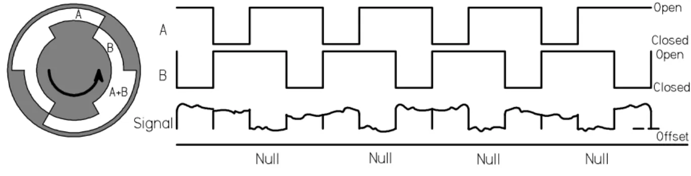
The nulled beam is chopped using a mechanical chopper which allows measurement of the intensity of each beam (IA, IB)
individually as well as both beams together (IAB). This means that at any moment during the nulling cycle, given a
knowledge of the electronic and sky offsets, the instantaneous null can be calculated based on the detected signal and the means of the individual beams during their open phase. The process is illustrated in Figure 8. The instantaneous null depth during the nulling part of the cycle is given by:
B A B A AB I I I I I N ˆ ˆ 2 ˆ ˆ + + =
where the quantities in the denominator are averages of the single beam intensities during the last cycle. The measured intensities have their background offsets removed.
3.3 Fiber fringe trackers
A pair of fringe tracking detectors use light centered at 1.65 µm (H-band) to maintain the null to a level better than that
provided by the AO system. The fringe tracking light is split 50/50 and sent to two single mode fibers which feed the light to thermoelectrically cooled detectors, in the same arrangement as the null detector. By laterally displacing the receiving fiber from the exact center of the interference fringe, any desired phase can be chosen. For fringe tracking, one fiber is displaced to the left by a sufficient distance to bring the interference phase to -π/2, the other is displaced to the
right by π/2. Thus the two detectors see signals with identical intensities (F1 and F2) but opposite sensitivity to phase
changes. The phase φ of the nulled beams is calculated using the fringe tracker outputs as
) /( ) ( ) sin(φ ≈ F1−F2 F1+F2 .
Initially, the fringe tracker phase is measured at the null of the K-band light and then the fringe tracking software maintains this phase by controlling the piston mirrors.
A B A+B A B Signal
Null Null Null Null
Offset Open Closed
Open Closed
Figure 8: The chopper wheel and the chop cycle. Apertures A and B allow beams 1 and 2 to strike the fiber in turn. Then both apertures are opened and the null is measured. Electronic and sky offsets must also be removed from the data.
3.4 Detectors
Three kinds of detectors are being used, not counting a CCD camera used for setup and alignment. The null and fringe tracker detectors are 250 µm diameter InGaAs detectors with extended wavelength response and a 10° FOV. They have
four stage thermoelectric coolers that allow them to operate at -85° C. The null detector has a response to 2.6 microns while the fringe tracker detector cutoff is 1.9 microns with slightly lower noise.
At the Palomar 200" telescope the apertures used are about 1.5 in diameter and will give about 400 pW at H-band (fringe trackers) and 150 pW at K-band (nulling, mean signal) at the detectors for an M type star with a K magnitude of zero.
The detector amplifiers have a large gain (109) with a 100 Hz bandwidth. The expected SNR in the fringe tracking
channels is about 3000 and is dominated by photon noise. For the nulling signal the bandwidth is ~10 Hz and the SNR is 2500. For the nuller the primary SNR contribution is from the detector.
The pointing detectors are InGaAs quad cells operating at J-band. For the same star as above the SNR per element is 2500 in a 400 Hz bandwidth.
3.5 Alignment
Several picomotors and piezo-electrically controlled stages are used to maintain alignment. At the left of Figure 6 the first fold mirror allows control of the input beam shear and the second fold mirror adjusts pointing. A combination of adjustments to these mirrors is made to position the incoming light centrally over the dual apertures. An initial measure of the beam shear can be made using the pointing sensor total outputs; when these are balanced the beams are centered. The tip/tilt stages can then be used to point the incoming beams individually onto the nulling fiber. The chopper wheel is rotated to allow adjustment of each beam in turn. Having established the alignment, the position is measured on the quad cell and a control loop then maintains the pointing using the tip/tilt mirror. The fringe trackers can be adjusted by making small position changes to their respective fibers so as to bring them to the correct phase.
3.6 Control
System alignment, control, and calibration techniques and software have been developed and tested as necessary parts of the instrument. The control system is based on a dual processor PC. Analog signal input and output is accomplished using a set of boards giving 16 output channels and 16 input channels. All the I/O channels operate simultaneously at 5 kHz, so that data is always synchronized with a single master clock. Simultaneously, all input and output data and much other information is logged to a hard disk. In post-processing, relevant data streams can be selected for analysis. In addition, real-time data can be observed in a 3 second long ring buffer so that detector inputs can be used for processes such as fringe-finding without having to log to disk.
All real-time processes run on one of the two CPUs which loops continuously to execute its I/O activities and data processing. The user’s control processes run under Windows-XP on the second processor, and access to the real-time process is achieved through Active-X calls. Control routines for the testbed are scripted in Matlab. This enables access to data and control of the real-time process directly without interfering with the timing. Control can be achieved either by command line scripts or via graphical user interfaces (GUIs). The result is a flexible system which when coupled with the data logging facility allows access to the data and control signals at both high and low levels as needed.
3.7 Image reconstruction
The image reconstruction method involves testing the measured signal for a full rotation of the aperture against computed signal templates for a range of possible companion object positions. The template is made by varying the phase of two beams of light from a simulated companion object in a sinusoidal fashion so that the object appears to move from one side of the star to the opposite side and back again. The phases ψ for light in the two apertures relative
to the center of the telescope are given by:
and ) 2 cos( t R A πλ πω ψ = Ω πω π π λ π ψB = RΩcos(2 t+ )+
where R is the distance of the aperture from the telescope center, λ is the infrared wavelength, Ω is the angular offset of
the companion from the star and 2πωt is the rotation angle of the aperture mask. An additional offset of π has been
introduced for the second aperture to simulate the nulling effect so that for an on-axis object with Ω equal to zero, the
phases ΨA and ΨBare zero and π, and for an off-axis object with RΩ/λ equal to one half, the phases ΨA and ΨBare π/2 and π/2, so they are constructively interfered.
Characteristic signals will be obtained from the companion object depending on its angular separation from the star. To detect the object’s signal in the output signal, which will contain substantial noise, the measured signal for one or more rotations will be compared with (correlated with) a series of object signal templates. Two such signal templates are shown in Figure 9. (These template models exclude details of the effect of the limited field of view.) The correlation will yield a two-dimensional map of the correlation in space as shown in Figure 10. A second, similar processing step will yield absolute planet signal magnitude.
38 72 108 144 180 218 262 288 324 380 Figure 9: Signal template models for objects at ~0.8 (blue) and ~1.2 (red) µradian from the star. The aperture separation is
3.3 m and the wavelength is 2.25 µm. Vertical axis is intensity in arbitrary units. The horizontal axis represents a single
rotation of the input apertures.
To test a recorded signal S(t) for the presence of a companion signal we create a series of companion object signal templates T(R,θ, t) where R is the radius from the star, θ is the rotation angle and t the time and calculate:
) , , ( * ) , , ( ) , , ( * ) ( ) , ( t R T t R T t R T t S R θ θ θ θ
∑
∑
= Φ (1)for all values of θ (0 to 2π) and R of interest. If S contains a companion object the result is proportional to the object’s
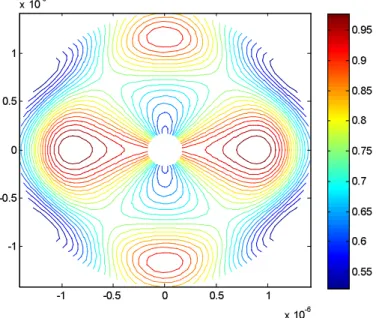
intensity. -1 -0.5 0 0.5 1 x 10⁻⁶ -1 -0.5 0 0.5 1 x 10⁻⁶ 0.55 0.6 0.65 0.7 0.75 0.8 0.85 0.9 0.95
Figure 10: Simulation of the correlation map for an object located ~0.9 µradian from the star. The object was positioned on
the center right. The star is nulled and is at the center. The object has a symmetric image on the left side of the star.
4. CONCLUSION
A fiber nulling coronagraph has been built for use on the Palomar 200” telescope. It implements a rotating two aperture nulling interferometer using the large telescope mirror. The Palomar adaptive optics system will correct most of the atmospheric disturbance across the telescope and a fringe tracking system has been included to remove the residual disturbances. Target null depths for the instrument are modest, around 500:1, while the null depths achieved on the internal source on the Palomar AO bench so far are at 200:1. Both the fringe tracker and the nulling beam combiner use the principle of combination on a single mode fiber, leading to a relatively simple in-line optical system without beamsplitters. Relative phase control is achieved using a pair of piezoelectrically controlled mirrors moving in differential piston. These mirrors also control the internal beam alignment which is sensed using a pair of quad cells. An alignment camera is also included to assist with initial setup. In forthcoming engineering trials on the telescope, the instrument will be used to look at bright binaries and also at single stars for calibration purposes.
Acknowledgements
This work was carried out at the Jet Propulsion Laboratory, California Institute of Technology, under contract with the National Aeronautics and Space Administration.
REFERENCES
[1] “DARWIN mission proposal to ESA”. Alain Leger, Tom Herbst, et al., submitted 23 Jul 2007. Astrophysics,
arXiv:0707.3385v1 [astro-ph].
[2] “Design Study for a Planet-Finding Space Interferometer”. Stefan Martin, Daniel P. Scharf, Richard Wirz et al.
IEEE Aerospace Conf, Big Sky, Mt, USA. March 2008.
[3] “Accessing Small Inner Working Angles with a Rotating Sub-aperture Nuller”. E. Serabyn and B. Mennesson,
Proceedings IAU Colloquium No. 200, 2005.
[4] “Testing the TPF Interferometry Approach Before Launch”. E. Serabyn and B. Mennesson. IEEE Aerospace Conf,
Big Sky, Mt, USA. March 2005.
[5] O. Wallner, J.M.P. Armengol and A. Karlsson 2004, “Multi-axial single-mode beam combiner,” in Proc. SPIE
5491, 798
[6] P. Haguenauer and E. Serabyn, 2006, Applied Optics, in press.
[7] “Terrestrial planet finder interferometer: 2006-2007 progress and plans”. P. R. Lawson et al. Proc SPIE, Volume
6693, Sept 19th, 2007.
[8] “Current progress on TPF-I mid-infrared achromatic nulling at the Jet Propulsion Laboratory”. Robert O.
Gappinger, Rosemary T. Diaz, Stefan R. Martin, Frank M. Loya, Peter R. Lawson. Proc SPIE, Volume 6693, Sept 19th, 2007.