HAL Id: tel-02409262
https://tel.archives-ouvertes.fr/tel-02409262
Submitted on 13 Dec 2019HAL is a multi-disciplinary open access
archive for the deposit and dissemination of sci-entific research documents, whether they are pub-lished or not. The documents may come from teaching and research institutions in France or abroad, or from public or private research centers.
L’archive ouverte pluridisciplinaire HAL, est destinée au dépôt et à la diffusion de documents scientifiques de niveau recherche, publiés ou non, émanant des établissements d’enseignement et de recherche français ou étrangers, des laboratoires publics ou privés.
On the Study of Large-Dimension Reconfigurable
Cable-Driven Parallel Robots
Dinh Quan Nguyen
To cite this version:
Dinh Quan Nguyen. On the Study of Large-Dimension Reconfigurable Cable-Driven Parallel Robots. Automatic. UNIVERSITE MONTPELLIER 2, 2014. English. �tel-02409262�
Délivré par UNIVERSITE MONTPELLIER 2
Préparée au sein de l’école doctorale : Information,
Structures, Systèmes
Et de l’unité de recherche : Laboratoire d’Informatique de
Robotique et de Microélectronique de Montpellier
Spécialité : Génie Informatique, Automatique et Traitement
du Signal
Présentée par Dinh Quan NGUYEN
Soutenue le 18/12/2014 devant le jury composé de
Mr. Jacques GANGLOFF, Professor, University of Strasbourg, France
Reviewer
Mr. Andreas POTT, Professor, University of Stuttgart, Germany
Reviewer
Mr. Cédric BARADAT, Director of Technology, Tecnalia France
Examiner
Mr. François PIERROT, Research Director, LIRMM/CNRS, France
Supervisor
Mr. Marc GOUTTEFARDE, Researcher, LIRMM/CNRS, France
Joint Supervisor
On the Study of Large-Dimension
Reconfigurable Cable-Driven Parallel Robots
A
CADÉMIE DEM
ONTPELLIERU
N I V E R S I T É
M
O N T P E L L I E R
II
Sciences et Techniques du LanguedocP
H
.D T
HESIS
présentée au Laboratoire d’Informatique de Robotique et de Microélectronique de Montpellier pour
obtenir le diplôme de doctorat
Spécialité : Génie Informatique, Automatique et Traitement du Signal
Formation Doctorale : Systèmes Automatiques et Microélectroniques
École Doctorale : Information, Structures, Systèmes
On the Study of Large-Dimension Reconfigurable
Cable-Driven Parallel Robots
by
Dinh Quan N
GUYEN
Soutenance on 18 December 2014, before the jury composed of :
President
Mr. Jacques GANGLOFF, Professor . . . University of Strasbourg, France
Reviewers
Mr. Andreas POTT, Professor . . . Uviversity of Stuttgart, Germany
Examiners
Mr. Cédric BARADAT, Director of Technology . . . Tecnalia France
Supervisor
Mr. François PIERROT, Research Director . . . LIRMM/CNRS, France
Joint Supervisor
A
CKNOWLEDGEMENT
First and foremost, my utmost appreciation to my thesis supervisor, Dr. Marc Goutte-farde, whose invaluable advice, guidance, patience, sincerity, encouragement I will never forget. My gratitude for his kind and constant support is beyond words.
I would like to express my thanks to all the partners involved in the CableBOT project: from CNRS LIRMM (Mr. Marc Gouttefarde, Mr. François Pierrot,...), from Tecnalia (Ms. Mariola Rodríguez, Mr. Micaël Michelin, Mr. Cédric Baradat), from INRIA (Mr. Jean-Pierre Merlet, Mr. Laurent Blanchet), from IPA Germany (Mr. Andreas Pott, Mr. Philipp Miermeis-ter), from UDE Germany (Mr. Tobias Bruckmann, Mr. Christopher Reichert, Ms. Katharina Müller), from EADS France (Mrs. Marie-Paule Guillou), from ACCIONA Spain (Mr. Manuel Palomino), from VICINAY CEMVISA Spain (Mr. Jesús Canãda, Mr. José Ignacio Olmos) and from the European commission (Mr. Vincenzo Nicoló). It was my great pleasure to work with them during the 3 years of CableBOT project. I have learnt a lot and gain a lot of in-valuable experience in cable robots, in robotics. During this time, I have the opportunities of meeting with many great people in various robotic fields all around the world.
I would also like to thank my friend and colleague, Johann Lamaury, with whom I had the pleasure of working in the same laboratory and sharing ideas on cable robots during my first two years. My great thanks to Pierre-Elie Herve, with whom I have spent days of exciting experiments on the CoGiRo prototype. Without his help I may get lost on the theoretical highway. Special thanks to Samah Shayya my neighbor colleague (his desk is right next to mine in the lab room), a workaholic and very academic friend. His comments and arguments on various topics related to kinematics and dynamics of parallel robots are greatly appreciated. I used to find myself ashame before his tenacity of doing research. Thanks to that sometimes it boosts me more energy to work harder during my PhD life.
Many thanks to all general staffs at LIRMM who helped me complete my thesis. Special thanks to Mr. Nicolas Serrurier, who is always be there giving kindness supports to PhD students like me to deal with complicated administrative procedures during my staying in Montpellier, France.
This thesis is dedicated to my dear parents and brother, who always give me the confi-dence and strength to pursue my goals. Their unconditional support and voices filled with love always give me energy and motivation.
C
ONTENTS
Acknowledgement I Contents III List of Figures VI List of Tables IX Notations X 1 Introduction 1 1.1 Thesis Context . . . 1 1.2 CDPRs: an Overview . . . 31.3 Recent Developments of Reconfigurable CDPRs . . . 12
1.4 On the Use of Large-Dimension Reconfigurable CDPRs in Two Targeted In-dustrial Applications . . . 13
1.4.1 Factory Workshop . . . 13
1.4.2 Airplane Maintenance Workshop . . . 21
1.5 Contributions and Content of the Thesis . . . 27
2 Preliminaries 29 2.1 General CDPR Modeling . . . 30 2.1.1 Kinetostatic Modeling . . . 30 2.1.2 Dynamic Modeling . . . 31 2.2 Cable Modeling . . . 32 2.2.1 Cable Profile . . . 33 2.2.2 Linearization . . . 36
2.2.3 A Limitation of the Simplified Cable Model . . . 37
2.2.4 Computation of the Cable Unstrained Length . . . 39
2.3 The Tension Distribution Problem . . . 41
2.4 Stiffness Matrix of CDPRs . . . 43
2.4.1 Stiffness Matrix of One Cable . . . 43
2.4.2 Stiffness Matrix of 6-DOF CDPRs . . . 45
2.5 On the Collision Detection Problems . . . 47
2.5.1 Interferences between Cables and Cables . . . 48
2.5.2 Interferences between Cables and the CDPR Mobile Platform . . . 51
2.5.3 Checking that a Given Workspace is Collision Free . . . 54
2.5.4 Example . . . 56
3 Extended Modeling - Application to the CoGiRo CDPR 59 3.1 The Modeling and Control of the CoGiRo CDPR . . . 61
3.1.1 Assumptions . . . 61
3.1.2 Using the Inverse Kinematics Solution in the CDPR Control Scheme . 63 3.1.3 Modeling of Friction . . . 64
3.2 Cable Profile with Thermal Effect . . . 67
3.2.1 Catenary Equation with Thermal Effect . . . 67
3.2.2 Linear Relationship between Cable Force Components . . . 68
3.3 CDPR Extended Modeling . . . 68
3.3.1 Cable Segment between the Drum and the Pulley . . . 68
3.3.2 Cable Segment between the Pulley and the Cable Anchor Point . . . . 70
3.4 Solving the Inverse Kinetostatic Problem Using the Catenary Cable Model . . 73
3.5 Error Analysis . . . 78
3.5.1 Impact of Thermal Effect . . . 79
3.5.2 Impact of Cable Characteristics . . . 80
3.5.3 Impact of the Method to Solve the CDPR Tension Distribution Problem 81 3.6 Case Study . . . 82
3.6.1 Case 1: Neglecting the Influence of the Pulleys and of Friction . . . . 82
3.6.2 Case 2: CoGiRo with Extended CDPR Modeling . . . 88
4 The CDPR Reconfiguration Problem 92 4.1 Introduction . . . 93
4.1.1 Large-Dimension Reconfigurable Suspended CDPR Architecture . . 93
4.1.2 The General Problem of CDPR Reconfiguration . . . 95
4.2 CDPR Reconfiguration as a Single-Objective Optimization Problem . . . 96
4.2.1 Performance Indices . . . 96
4.2.2 Step 1: Define Desired CDPR Performances . . . 97
4.2.3 Step 2: Formulate Two Optimization Sub-Problems . . . 98
CONTENTS V
4.2.5 Case Study . . . 101
4.2.6 Remark on the Methodology . . . 105
4.3 CDPR Reconfiguration as a Multi-Objective Optimization Problem . . . 107
4.3.1 Performance Indices . . . 109
4.3.2 Scalarization of the Performance Indices . . . 112
4.3.3 Systematic Procedure to Solve a Reconfiguration Problem . . . 114
4.3.4 Case Study . . . 115
5 Conclusion 121 Publications 125 Conferences . . . 125
A Complementary Modeling 127 A.1 Extended Modeling: a General Case . . . 127
A.1.1 Cable Segment between Two Vertically Aligned Pulleys . . . 129
A.1.2 Cable Segment between Two Horizontally Aligned Pulleys . . . 130
A.1.3 Cable Segment between the Drum and the First Pulley . . . 131
1.1 The NIST Robocrane . . . 7
1.2 The FALCON prototype . . . 7
1.3 The DeltaBot prototype . . . 8
1.4 The SEGESTA prototype . . . 8
1.5 The IPAnema CDPR family . . . 9
1.6 The ReelAx8 prototype . . . 9
1.7 The CoGiRo prototype . . . 10
1.8 The MARIONET crane prototype . . . 10
1.9 The FAST project . . . 10
1.10 Spidercam . . . 11
1.11 Skycam . . . 11
1.12 Handling heavy parts using cranes . . . 13
1.13 All winches are mounted on one overhead bridge crane . . . 15
1.14 A CDPR on two overhead bridge cranes . . . 16
1.15 All winches can move: two pairs on overhead bridge cranes, two pairs on side rails attached to the walls . . . 16
1.16 All winches can move: two pairs on overhead bridge cranes, two pairs on beams connecting the two bridge cranes . . . 17
1.17 Preferred Scenario: 8-cable suspended reconfigurable CDPR, all winches are mounted on two overhead bridge cranes . . . 17
1.18 Concept of cable-driven systems . . . 18
1.19 Case 6-Cable CDPR: All pairs of winches can move freely on overhead bridge cranes . . . 19
1.20 Case 8-Cable CDPR: All pairs of winches can move freely on overhead bridge cranes . . . 19
List of Figures VII
1.21 Case 8-Cable CDPR: on each overhead bridge crane, 1 pair of winches (or ca-ble exit points) is fixed at the middle, the other two pairs can move (within a restricted range). Additional movable beams might be used to sustain lateral
forces exerted on the two cranes. . . 20
1.22 Using multiple CDPRs in a factory workshop . . . 20
1.23 Conventional method of carrying workers in an airplane maintenance workshop 21 1.24 Using grid of winches to reconfigure CDPRs in 4 sections over the airplane body 23 1.25 All pairs of winches can move on fixed rails along the airplane body . . . 23
1.26 All pairs of winches can move on reconfigurable rails (this solution is similar to factory workshop use case) . . . 24
1.27 Fully constrained CDPRs: 4 winches can move on the rails on top of the airplane body, the other 4 winches can be switched among a grid of winches on the ground 24 1.28 Solution of using 4 CDPRs in an airplane maintenance workshop: covered areas 25 1.29 Solution of using 4 CDPRs in an airplane maintenance workshop: perspective view . . . 25
1.30 Modified mobile platform: perspective view . . . 26
1.31 Modified mobile platform: elongate the platform working area to reach the lower part of airplane body . . . 26
2.1 General m-cable CDPR . . . 30
2.2 Diagram of a sagging cable in 2D (cable local frame) . . . 33
2.3 Sketch of a sagging cable in 3D . . . 43
2.4 A general m-cable CDPR . . . 48
2.5 Usual method to check interference between two cables . . . 49
2.6 Checking interference between two cables . . . 50
2.7 Interferences between cables and the CDPR mobile platform . . . 52
2.8 Simplification of the mobile platform shape . . . 52
2.9 Detecting collision between cable i and the mobile platform . . . 53
2.10 Example of an 8-cable CDPR . . . 56
3.1 Winch and cable transmission components of the CoGiRo prototype . . . 60
3.2 Control scheme of the CoGiRo prototype used in the experiments . . . 63
3.3 Measured output torque of the motor . . . 65
3.4 Steady-state values of the friction torque . . . 66
3.5 Cable segment AB . . . 70
3.6 Solving the CDPR inverse kinetostatic problem using catenary cable . . . 74
3.8 The change of cable unstrained length due to the change of the cable Young’s
modulus . . . 80
3.9 The CoGiRo CDPR . . . 81
3.10 Maximum errors of the cable unstrained length computed from different ten-sion distribution methods . . . 82
3.11 Accuracies of different cable models - Case 1a : following a desired trajectory . . 83
3.12 Accuracies of different cable models - Case 1b : varying payloads . . . 84
3.13 CoGiRo control scheme: Without the influence of pulley kinematics . . . 86
3.14 Static equilibrium poses in the workspace of CoGiRo - Case study 1 . . . 86
3.15 CoGiRo control scheme: Including the influence of pulley kinematics . . . 88
3.16 Static equilibrium poses in the workspace of CoGiRo - Case study 2 . . . 89
4.1 Solution using large-dimension reconfigurable suspended CDPR to replace conventional cranes . . . 94
4.2 Example of a scenario in a workshop . . . 101
4.3 Bounds on reconfiguration parameters and desired Cartesian workspace . . . . 103
4.4 Desired trajectory . . . 104
4.5 Results of online reconfiguration . . . 105
4.6 Solution for the upper bounds on the reconfiguration parameters . . . 106
4.7 CDPR Mobile platform . . . 108
4.8 Displacements of Op and M at the mobile platform of a CDPR . . . 110
4.9 Using CDPRs to replace gantry nacelles in an airplane workshop . . . 115
4.10 Reconfiguration parameters . . . 117
4.11 Reconfiguration solutions in case nr= 4 . . . 119
A.1 Drum and cable transmission components: a general case . . . 128
A.2 Cable segment between two vertically aligned pulleys . . . 129
A.3 Cable segment between two horizontally aligned pulleys . . . 130
A.4 Cable segment between the drum and the first pulley . . . 132
L
IST OF
T
ABLES
2.1 Collision detection computation times . . . 57 3.1 Loss of torque due to friction in the winch . . . 66 3.2 Measured positions of the mobile platform of CoGiRo at several static
equilib-rium poses - Case study 1 . . . 87 3.3 Positioning accuracy of CoGiRo at several static equilibrium poses - Case study 1 87 3.4 Measured positions of the mobile platform of CoGiRo at several static
equilib-rium poses - Case study 2 . . . 90 3.5 Positioning accuracy of CoGiRo at several static equilibrium poses - Case study 2 90 4.1 Results obtained by solving the different optimization problems . . . 119
In the thesis, a vector is expressed either as a lower-case bold letter (e.g. f) or as an upper-case italic letter (e.g. F ). A matrix is expressed as an upper-case bold letter (e.g. R).
The variables with a subscript containing the letter L (e.g. coordinate xLbor force
com-ponent fLbx) indicates that these variables are expressed in the local cable frame. The
vari-ables without subscription letter L are expressed in global frame.
C DP R Cable-Driven Parallel Robots
I K P Inverse Kinetostatic Problem
kuk, kKk The 2-norm of a vector or a matrix
13×3 Identity matrix
03×3 Null matrix
(u)× Cross-product matrix of vector u (x1 x2) , [x1 x2]T Column vectors
[x1 x2] Row vectors
m The number of cables
Ai The base frame exit point of cable i
Bi The anchor point of cable i , onto the mobile platform
Op The origin of the local frame attached to the mobile platform
ui Unit vector that direct the cable force at the cable i anchor point
bi Position vector of Bi expressed in mobile platform frame < Op> C The center of mass of the mobile platform
R Rotation matrix of the mobile platform
S Matrix that maps angular velocities
onto the time derivative of Euler angle vector
X = (P,Φ) Pose vector of the mobile platform
Xc Home pose
Xd Desired pose
d X = (dP,dΦ) Infinitesimal displacement vector
d P = (d x,d y,d z) Displacement vector in Cartesian space
XI
dΦ = ¡dθx, dθy, dθz
¢
Displacement vector in orientation space
fe External wrench applied by the cable on the mobile platform d XH Homogeneous infinitesimal displacement vector
d feH Homogeneous infinitesimal wrench
mp Mass of the mobile platform
W CDPR wrench matrix (general case)
Wx CDPR wrench matrix (simplified cable model case)
W+, W+x Pseudo inverse matrices of wrench matrices
N, Nx Null-space matrices of wrench matrices
τb The vector of cable tensions at anchor points Bi τa,τb Cable tensions at cable end points A, B
τs Cable tension at a point with cable coordinate s τmin,τmax Lower bound and upper bound on cable tensions
FBi, FAi Cable force vector at end points Bi, Ai
ap Acceleration vector of the origin Op of the mobile platform frame
α Angular acceleration vector
ω Angular velocity vector
K Stiffness matrix of 6-DOF CDPR
KB Stiffness matrix of one cable
J CDPR Jacobian matrix
KH Homogeneous stiffness matrix
E Cable Young’s modulus
A0 Cable cross-section area
w Cable self-weight
L0 Cable unstrained length
αT Thermal expansion coefficient
T0 Reference temperature
µs Static friction coefficient between pulley and cable
Γf Loss torque due to frictional effect
L(P,Q)0 Cable unstrained length between two end points P,Q
r = (r1, r2, ...) Vector of reconfiguration parameters
rmin, rmax Lower and upper bound vectors on the reconfiguration parameters
Cr Set of reconfiguration parameters that satisfy all constraints
ropt Optimal reconfiguration (planning) solution
4r Maximum step size of reconfiguration parameters
fΣ Sum of cable tensions index, wrt. a given workspace
σM Normalized upper bound on the infinitesimal displacement vector
C
H A P T E R1
I
NTRODUCTION
Summary
1.1 Thesis Context . . . 1 1.2 CDPRs: an Overview . . . 31.3 Recent Developments of Reconfigurable CDPRs . . . 12 1.4 On the Use of Large-Dimension Reconfigurable CDPRs in Two Targeted
Industrial Applications . . . 13 1.5 Contributions and Content of the Thesis . . . 27
1.1 Thesis Context
CABLEBOT
The research leading to the results presented in this thesis is associated with the Cable-BOT project1, an European Community’s Seventh Framework Programme project under grant agreement No. NMP2-SL-2011-285404.
The main objective of the CableBOT project is to develop a new generation of modular and reconfigurable CDPRs that are capable to perform many different steps in the life-cycle stages of large-scale structures.
1. http://www.cablebot.eu
Within CableBOT two fields of application were targeted in close cooperation to indus-try: Aircraft life-cycle maintenance in the aerospace industry and the construction beams post-production handling.
Several issues were addressed in the project:
– Design of reconfigurable CDPRs: Preferred implementations of reconfigurable CD-PRs were proposed as solutions to the two targeted industrial applications. Powerful software tools have been developed to deal with the design and reconfigurations of CDPRs.
– CDPR simulation tools: A C++ framework has been developed allowing to create sim-ulation scenes of CDPRs composed of elementary components such as winches, pul-leys, cables and mobile platform. This software framework can be used in the design and control of CDPRs.
– CDPR control modules: Control schemes and algorithms have been developed and applied on different CDPR prototypes, providing solutions to various application scenarios.
THESIS GOAL
The main objectives of the thesis are directly related to the CableBOT project goals. We seek for possible solutions of using reconfigurable CDPR to replace conventional methods of handling large and heavy parts in a workshop.
A reconfigurable CDPR can change its geometry by adjusting the cable exit points po-sitions or by reordering or changing the popo-sitions of the cable attachment points onto the mobile platform. Reconfigurability should enable the robot to adapt to a variety of tasks and dimensions. A reconfigurable CDPR should thus fulfil several requirements, e.g. hav-ing suitable architectures (geometries) that satisfy the followhav-ing typical constraints, which represent robot capabilities:
– All poses of a given workspace can be reached. – Workspace is singularity free.
– Adequate degrees of freedom are kept across the whole workspace. – Cable tensions satisfy minimum and maximum values.
– Workspace is collision free (no cable interferences, no collision with objects in the workspace,...).
– Ability to balance varying reaction forces due to carried devices (e.g. robot arm) or workers.
1.2. CDPRS: AN OVERVIEW 3
To this end, we aim to develop a fundamental framework for reconfigurable CDPRs. It consists of several topics:
1. The general architecture of the studied reconfigurable CDPR family is required. This architecture should enable the CDPRs to achieve most of the desired tasks and its implementation in the assigned environment should be feasible (e.g. in a factory workshop or in an airplane maintenance workshop).
2. Analysis tools that can aid the design and control of reconfigurable CDPRs. 3. Methods and tools to solve the CDPR reconfiguration problem efficiently.
1.2 CDPRs: an Overview
CDPRs have been an active research topic in the past decades in favor of their appeal-ing advantages such as light-weight, simple in design, easy to reconfigure and implement, high payload to weight ratio and relatively low cost. Compared to parallel manipulators with rigid links which are limited to work in small work cells, CDPRs use cables to position their mobile platform (end-effector) directly by controlling the length of each cable and can thus be adapted to very large workspaces. However, the use of cables can also have some peculiar drawbacks. Firstly, cables can transmit tension forces but not compression forces. Thus, all the cables driving the mobile platform should be under tension such that the tension value lies in an admissible tension range. Secondly, the nonlinear characteris-tics of the cables might affect the robot performance. These factors increase the difficulty of important issues such as the CDPR kinematic and dynamic modeling, tension distribu-tion, workspace analysis and control schemes. In other words, most of the methods related to rigid-link parallel manipulators have to be modified for CDPRs.
Possible applications of CDPRs are positioning and handling of large and heavy parts across wide workspaces such as for structure construction [1, 2], rescue operation [3, 4], rehabilitation [5, 6, 7], aerial transportation [8, 9], astronomical observation [10].
CLASSIFICATION OF CDPR
The first general classification of CDPRs was given by Ming and Higuchi [11]. Based on the number of cables (m) and the number of degrees of freedom (n), cable-driven parallel robots were classified into two categories, namely the incompletely restrained positioning mechanisms IRPM (m < n + 1), the completely restrained positionpositioning mechanisms -CRPM (m = n + 1) . In [12], Verhoeven introduced one more category which is the redun-dantly restrained positioning mechanisms - RRPM (m > n + 1).
In terms of force-closure (wrench-closure), CDPRs are classified into two main cate-gories: fully constrained and under-constrained. For the first category, there exists at least one mobile pose having force-closure, for which any wrench applied on the platform can be balanced through tension forces in the cables [13]. Notable examples are the FALCON prototype [14] and the SEGESTA prototype [15]. On the contrary, for under-constrained CDPRs, the cables cannot balance any external wrench because to this end, they might have to push on the platform. Gravity is then used to keep the cables under tension. The latter case can be referred to as suspended CDPRs (all the cables are “above" the mobile platform), e.g. the NIST ROBOCRANE [16] or the CoGiRo prototype [17].
KINETOSTATIC MODELING OF CDPR
In the kinematic modeling of CDPRs, different cable models were used in previous works, including massless elastic model (straight line) [14, 18, 19, 20, 21, 22], simplified model (parabolic model) [23], and catenary model [24]. The massless elastic cable model is sufficient in many CDPR case studies. However, the effect of cable sagging due to cable mass and elasticity, especially for large-dimension CDPRs, may have great impact on the robot performance and thus should be considered in the kinematic modeling. Ottaviano presented an analysis of the effects of the cable mass and elasticity on the end-effector of a planar 2-DOF CDPR in [25]. The studies in [26, 27] specifically discuss the difference in the CDPR workspace when using the simplified or catenary cable model compared to massless elastic cable model.
Tension distribution is another important issue, especially in the case of redundant CDPRs. Several real-time capable tension distribution methods have been developed [15, 18, 19, 28, 29, 30, 31, 32, 33]. Two main approaches are applied. The first approach uti-lizes fast optimization tools to obtain the tension distribution in optimizing certain criteria. For example, Lim et al. in [31] use a gradient projection method to compute the solutions. Meanwhile, the authors in [29, 34] address the same problem by using minimization of the Euclidean norm of the cable tensions and p-norm of the relative cable tensions to avoid cable tension discontinuities that may be caused by linear programming. In the second approach, e.g. in [32, 33], the solutions of cable tensions are found for redundantly ac-tuated CDPRs based on geometric considerations applied to the two-dimensional convex polytope of feasible cable tension distributions. This polytope is defined as the intersec-tion between the set of inequality constraints on the cable tension values and the affine space of tension solutions to the mobile platform static or dynamic equilibrium. The so-lutions also guarantee the continuity of cable tensions in a continuous trajectory of the CDPR mobile platform.
1.2. CDPRS: AN OVERVIEW 5
Regarding the workspace analysis, a number of studies on the determination of CDPR workspaces have been made [1, 27, 35, 36, 37, 38]. In [39], an interval analysis based tool is developed to compute the Wrench-Feasible Workspace (WFW) of a CDPR. Several studies quantified the CDPR workspaces based on classical criteria which were used for rigid-link parallel manipulators. For example, in [40] Hay analyzed the CDPR dexterous workspace, which refers to the intersection of orientation workspaces with a range of rotation angles. The workspace “quality" of a CDPR can also be evaluated based on indices derived from its stiffness matrix (which can be used to account for the CDPR stability) [41, 42, 43].
In term of CDPR dynamics, most of previous studies consider only the dynamics of the mobile platform and the winches. Cable dynamics has rarely been addressed due to its complexity. Du et al. [44] evaluated the effect of cable vibration on the positioning accuracy of the end-effector of a large-dimension CDPR by using finite element method. In [45], Yuan et al. analyzed the elastodynamic of a 6-DOF suspended CDPR. They con-struct the dynamic stiffness matrix of a sagging cable and study the natural frequency of the CDPR mobile platform. They showed that the cable dynamics should be considered when it comes to perform high speed applications. In a more recent work [46], Weber made an analysis on the cable dynamics and proposed a method to reduce the vibration effect at the mobile platform of a 2-DOF CDPR.
CDPR CONTROL PROBLEM
Many control schemes used for rigid-link parallel manipulators may be adapted to cable-driven parallel robots. The most common approach is to drive the mobile platform by means of controlling the cable lengths or the required torques. A feedback control loop allows the realization of desired cable lengths corresponding to a desired position and ori-entation of the mobile platform, or of the motor torque corresponding to a desired CDPR dynamics. In [47], Fang et al. proposed nonlinear feedforward control laws in the joint space, taking the advantage of an optimal tension distribution. Williams et al. [48] pro-posed a computed torque controller using the encoder feedback for each cable length. Motion convergence using simple control laws (e.g. PD feedback controller) in the joint space was proven with a Lyapunov function and a "vector closure" analysis by Kawamura et al. [49]. Kino et al. [50] proposed a robust PD controller with an adaptive compensa-tion for fully constrained CDPRs. In recent studies, Lamaury applied a dual-space feedfor-ward controller [17] (which was previously successfully implemented on rigid-link parallel robots [51]). This control scheme was also implemented with a PID control law and an adaptive control law considering the use of an effective tension distribution method [32]. Similar approaches have been applied by Bruckmann et al. [15, 33].
Controlling CDPRs in the joint space sometimes face the difficulty in accomplishing ac-curate pose of the end-effector mainly due to the use of simplified cable models. Attempts to control CDPRs in the task space have been carried out such as with visual servoing and using real-time forward kinematic modeling. Dallej et al. [52] proposed a 3D pose visual servoing and developed a vision-based computed torque control. In a recent study, Chellal et al. [53] also proposed a vision-based position control for a 6-DOF CDPR.
Keeping all the cables under tensions during operation is another issue of CDPR con-trol problems. The constraints set upon cable tensions make concon-trol of CDPRs a lot more challenging than their counterpart rigid-link parallel robots. Effective tension distribution methods can be used in the CDPR control schemes [15, 18, 19, 28, 29, 30, 31, 32, 33] . Taking the advantage of such methods, several control strategies were proposed to meet the conditions of positive cable tensions. Alp and Agrawal [54] described the structures of Lyapunov based controller and feedback linearizing controller that guarantee positive cable tensions. Oh and Agrawal [55, 56] proposed techniques to estimate the admissible workspace of set-point control for a cable-suspended robot under disturbances and input constraints based on a sliding mode controller. Alikhani [57] proposed a propagation algo-rithm in order to generate feasible set points for the end-effector motion while satisfying constraints on control inputs. In [58], Khosravi formulated a robust PID position control in task space and used a corrective term to ensure positive cable tensions.
NOTABLE CDPR PROTOTYPES AND APPLICATIONS
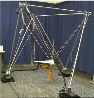
Since the 1980s, various CDPR prototypes have been built and studied. Early in 1989 the NIST Robocrane system for large-scale handling [16, 59, 60] is one of the first CDPR prototypes (Fig. 1.1). NIST implemented ROBOCRANE to carry on a series of application research on assembly, lifting, spraying, and building with cable robots [61, 62, 63, 64].
Later, an ultrahigh speed cable robot FALCON (Fig. 1.2), a 7-cable 6-DOF CDPR, was designed in Japan. One can say it was the first CDPR prototype for very fast pick-and-place applications [14, 49].
DeltaBot [65], a rigid-cable hybrid ultra-high-speed cable robot, was developed by Amir Khajepour at the University of Waterloo, Canada (Fig. 1.3).
SEGESTA (Fig. 1.4), another lightweight prototype, was developed at the University of Duisburg-Essen, Germany. A number of studies have been made with SEGESTA on the kinematic modeling, workspace calculation, tension distribution, and trajectory planning issues [15, 18, 28, 66, 67].
1.2. CDPRS: AN OVERVIEW 7
Figure 1.1: The NIST Robocrane
Figure 1.3: The DeltaBot prototype
1.2. CDPRS: AN OVERVIEW 9
Figure 1.5: The IPAnema CDPR family
Figure 1.6: The ReelAx8 prototype
The IPAnema family of cable robots (Fig. 1.5) is developed by Fraunhofer IPA, Germany for medium to large scale inspection, handling, and assembly operations [2, 19, 30, 68].
LIRMM and Tecnalia France developed two redundantly actuated 8-cable CDPR pro-totypes: the small-medium workspace CDPR ReelAx8 (Fig. 1.6) and the large-dimension suspended CDPR CoGiRo (Fig. 1.7) [17, 32, 69, 70].
The CDPR prototype MARIONET crane (Fig. 1.8) for rescue and personal assistance was developed at INRIA in France [71].
The 500-meter Aperture Spherical radio Telescope (FAST), which is currently under construction in the Karst region of Guizhou Province, China [72, 73, 74] would be the world’s largest cable robot. The FAST is composed of the active main reflector and the feed support system. The huge CDPR and the feed cabin constitute the feed support
sys-Figure 1.7: The CoGiRo prototype
Figure 1.8: The MARIONET crane prototype
1.2. CDPRS: AN OVERVIEW 11
Figure 1.10: Spidercam
Figure 1.11: Skycam
tem. The CDPR with the radius of 600m is driven with six steel cables, providing receivers with large workspace (Fig. 1.9).
Spidercam in Germany [75] (Fig. 1.10) and Skycam in USA [76] (Fig. 1.11) are two suc-cessful applications of CDPRs used to carry a camera over a very large area (e.g. in a soccer stadium), allowing the camera to be positioned at different angles and positions.
1.3 Recent Developments of Reconfigurable CDPRs
Most of the studies on CDPRs in the past decades have been focused on fixed config-uration CDPRs where the cable exit points and attachment points are fixed at pre-defined locations. The properties of a CDPR in general can be easily changed by re-adjusting its cable layout, e.g. by adjusting the locations of the cable exit points or by changing the attachment order or positions of the cables connected to the mobile platform (or to the end-effector). For example, one can transform a fully constrained CDPR (e.g. IPAnema prototype in Fig. 1.5) into an under constrained suspended CDPR (e.g. CoGiRo prototype in Fig. 1.7) simply by moving the cable exit points to any positions where all the cables are above the mobile platform.
Recent studies [4, 77, 78, 79] deal with reconfigurable CDPRs where the geometry of the CDPRs can be reconfigured by changing its cable layout. Reconfigurability of a CDPR could greatly increase its capability (compared to fixed configuration CDPR), but at the same time, it adds redundancy and increases the complexity of the system . For the design of such CDPRs, in [77], Rosati introduced the concept of adaptive cable-driven systems. He discussed a systematic procedure to determine the design solution for planar cable-driven systems which minimizes or maximizes some local performance indices such as cable ten-sion based criteria and dexterity of the CDPRs. Later on, Xiaobo Zhou in [78] presented an analysis framework for cooperating cable mobile robots. The proposed method to solve the reconfiguration problem is similar to that of Rosati in the sense that the solutions were derived from optimizing certain criteria. In [79], Zhou et al. proposed a generalized mod-eling framework for systematic design and analysis of cooperative mobile cable robots. They dealt with the redundancy resolution by optimally repositioning the mobile bases to maximize the so-called tension factor which is the ratio between minimal and maximal values of cable tensions along a given trajectory. However, all these previous studies only consider planar robot systems where important constraints such as cable interferences are not taken into account. Moreover, critical issues while using standard optimization tools to solve the redundancy of the robot system such as the continuity of the performance
in-dices with respect to the deciding parameters and the continuity and differentiability of the constraints have not been addressed. In fact, the continuity of the tension based
perfor-mance indices can be dealt with by using tension distribution methods such as the one in [32]. However, it is difficult to address the second issue since there are different types of constraints including wrench feasibility (continuous nonlinear constraints) and cable interferences (non-differentiable constraints). Furthermore, the problem becomes more complex for a highly redundant CDPR. Addressing these issues of reconfigurable CDPRs is one of our main objectives in the present thesis.
1.4. ON THE USE OF LARGE-DIMENSION RECONFIGURABLE CDPRS IN TWO
TARGETED INDUSTRIAL APPLICATIONS 13
1.4 On the Use of Large-Dimension Reconfigurable CDPRs
in Two Targeted Industrial Applications
Cable-driven parallel robots possess many appealing advantages. The use of cables provides great potential to CDPRs such as a wide workspace and high payload to weight ratio. We shall give a brief discussion of two possible applications for which CDPRs could replace conventional methods of handling large and heavy parts across wide workspaces. These two applications were considered in the framework of the CableBOT project.
1.4.1 Factory Workshop
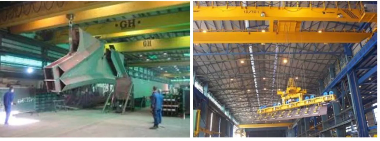
Fig. 1.12 shows conventional methods to handle large and heavy parts in a workshop. In the left (Fig. 1.12a), one or multiple overhead cranes are used to manipulate the parts. Each crane offers one degree of freedom along the vertical axis and one or two degrees of freedom in lateral directions. This solution has several drawbacks including limited flexi-bility and reduced orientation capabilities. Most of the time when the operation requires a change of orientation of the part, there is a need of involving workers which causes safety issues. For tasks that require several degrees of freedom of the part, such traditional meth-ods may not be sufficient. When lifting devices need more than one degree of freedom, they are complemented with other mechanisms that provide extra DOFs. As shown in Fig. 1.12b, the crane need an extra device to enable its rotational capability for some tasks that require rotational DOFs.
In those cases, using a CDPR would be much more convenient. By simply connecting
(a) Manipulating heavy part using multiple cranes (b) Crane with 10t vacuum prehension, 5 DOF
the cables directly to the parts, the CDPR can execute the tasks that require up to 6-DOF movements.
REQUIREMENTS
In a workshop, examples of tasks are the displacement of heavy structure elements (dis-place structure components from one (dis-place to another within the workshop) or position-ing of structure elements for assembly. Expected CDPR performances can be foreseen as follows:
– Number of degrees of freedom required by the tasks: For positioning tasks, the CDPR should have at least 4-DOF: translations in all directions and rotation around the vertical axis (e.g. up to ±90o). For assembly tasks, six DOFs are generally required. – Workspace: The robot must fit into the workshop area. Depending on the layout of a workshop, a CDPR is expected to cover a certain area or several connected sections in the workshop.
– Required speed or cycle time: The speed of the movements depends highly on the weight to be displaced. For light weight part, high speed motions can be used. For heavy payload (several tons), slow motion is expected. However, in both cases, the CDPR should be able to achieve a given desired performance in terms of maximum acceleration and velocity.
– Required accuracy and stiffness: Positioning structure elements may require a weak accuracy. However, in assembly tasks, high precision and high stiffness at the end-effector could be required. These factors could be attainable by using suitable con-figuration of the CDPR.
– Requirements on reconfigurability of the CDPR: The geometry and weight of the structures elements can change. Therefore, the CDPR has to be somehow recon-figurable, in order to fulfill the task requirements. When the CDPR uses its mobile platform to handle the part, an additional fastening device may be required to attach the part to the mobile platform. Alternatively, in the case the structure part itself be-comes the mobile platform of the CDPR, a suitable strategy to attach the cables to the part is required. On the other hand, the geometry of the CDPR may need to be reconfigurable in order to fulfill different task requirements (e.g. obtaining a larger orientation range within a specific area).
1.4. ON THE USE OF LARGE-DIMENSION RECONFIGURABLE CDPRS IN TWO
TARGETED INDUSTRIAL APPLICATIONS 15
PROPOSED CDPR ARCHITECTURES
It is common to use overhead bridge cranes to span all area in a workshop. As an evolution of this solution, it could be convenient to construct CDPRs using these cranes. Fig. 1.13 shows the first solution where each crane carries one CDPR. The mobile platform can be the structure part (load) itself - on which several anchor points are pre-defined to connect the cables. The winches may move freely on the overhead bridge to ensure maxi-mum flexibility. The number of winches in this case can be varied depending on the actual need. It is to be noted that 6 winches and, hence, 6 cables may be necessary to avoid com-plex motions resulting from under-constraining the 6 degrees of freedom of the load. In this solution, the CDPR workspace is limited. It is not much different from a conventional crane except that it provides more rotational capability.
In a second implementation (Fig. 1.14), the CDPR is constructed by using two overhead bridge cranes. This solution should offer more flexibility in terms of workspace and in handling large structure parts.
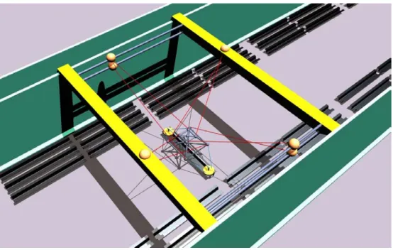
One can imagine different approaches to positioning the cable exit points of the CDPR in order to enable its reconfigurability. Fig. 1.15 shows a possible implementation of a re-dundant 8-cable 6-DOF CDPR where the cable exit points can move by pairs along different directions. There are two pairs mounted on side rails attached to the wall of the workshop. This solution is not necessarily feasible because the walls may have to sustain large lateral forces. One way to overcome this problem is to add extra beams that connect the two over-head bridge cranes. The cable exit points can then move along these additional beams as
shown in Fig. 1.16. In this way, the lateral forces acting on the side walls of the workshop are minimized. This approach offers great reconfigurability to the CDPR. However, the workspace is still limited which is depended on the length of the extra beams. Moreover, it is not trivial to design such a system.
Fig. 1.17 shows a preferred scenario where the four pairs of cable exit points of the CD-PRs are constrained to move along two overhead bridge cranes.
Figure 1.14: A CDPR on two overhead bridge cranes
Figure 1.15: All winches can move: two pairs on overhead bridge cranes, two pairs on side rails attached to the walls
1.4. ON THE USE OF LARGE-DIMENSION RECONFIGURABLE CDPRS IN TWO
TARGETED INDUSTRIAL APPLICATIONS 17
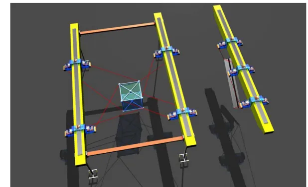
Figure 1.16: All winches can move: two pairs on overhead bridge cranes, two pairs on beams connecting the two bridge cranes
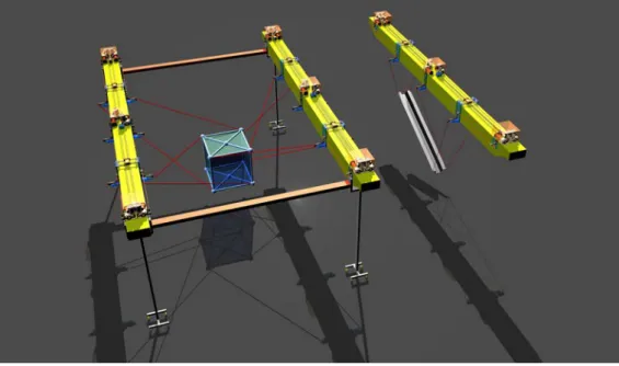
Figure 1.17: Preferred Scenario: 8-cable suspended reconfigurable CDPR, all winches are mounted on two overhead bridge cranes
PREFERRED SCENARIOS
Fig. 1.18 shows possible solutions to enable reconfigurability of a CDPR. The second case represents a more practical solution. It consists in only changing the position of the cable exit points. The winches are fixed at predefined locations on the overhead bridge crane.
The following figures Fig.1.19-1.21 detail several preferred CDPR architectures. In these solutions, the cable exit points are moving by pairs on each overhead bridge crane. To enable modularity of the system, all the cranes are similar to each other. Each of the crane can constitute a suspended CDPR. Furthermore, any two overhead bridge cranes can be used in collaboration to form a CDPR with 6 cables or 8 cables with a larger workspace and larger orientation capabilities. Fig. 1.22 shows a scenario where multiple CDPRs are used to work in different sections in a factory workshop.
Moving winches
Fixed winches Cable exit points can move
1.4. ON THE USE OF LARGE-DIMENSION RECONFIGURABLE CDPRS IN TWO
TARGETED INDUSTRIAL APPLICATIONS 19
Figure 1.19: Case 6-Cable CDPR: All pairs of winches can move freely on overhead bridge cranes
Figure 1.20: Case 8-Cable CDPR: All pairs of winches can move freely on overhead bridge cranes
Figure 1.21: Case 8-Cable CDPR: on each overhead bridge crane, 1 pair of winches (or cable exit points) is fixed at the middle, the other two pairs can move (within a restricted range). Additional movable beams might be used to sustain lateral forces exerted on the two cranes.
1.4. ON THE USE OF LARGE-DIMENSION RECONFIGURABLE CDPRS IN TWO
TARGETED INDUSTRIAL APPLICATIONS 21
1.4.2 Airplane Maintenance Workshop
In the second targeted industrial application, CDPRs may be used to replace conven-tional methods to perform maintenance tasks in an airplane workshop. Fig. 1.23 shows the general method where several telescopic platforms are used to carry the workers across the airplane fuselage. Each telescopic platform offers 4 degrees of freedom (three translations in Cartesian space and one rotation around the vertical z-axis) which allows the task to be done quite efficiently. However, this solution has some disadvantages. Firstly, each tele-scopic platform weights from 9 to 11 tons which implies high costs for the building con-struction to sustain such heavy systems. Secondly, the workers sometimes need to work in hazardous environment where the operation requires to use chemical material like paint or stripping products. In the latter case, using CDPRs to automatically handle the tasks could be a more preferable solution.
REQUIREMENTS
To be able to replace conventional methods in an airplane maintenance workshop, there are different requirements that the CDPRs must strictly follow:
– Number of degrees of freedom required by the tasks: Depending on specific tasks (painting, cleaning, inspection...), the number of degrees of freedom of the mobile platform is variable. It also depends on the tools or mechanical devices embedded on the CDPR mobile platform.
Chemical paint stripping
Painting
Figure 1.23: Conventional method of carrying workers in an airplane maintenance work-shop
– Workspace: The CDPRs are expected to reach all parts of the airplane body. Depend-ing on the size of the airplane, several CDPRs must be used to cover different areas of the workspace simultaneously. The airplane has to be approached by the CDPRs without any shock or collision.
– Required speed or cycle time: In some maintenance tasks (e.g. painting), fast po-sitioning of the mobile platform is required (e.g. velocity is greater than 0.6m/s) in order to complete the tasks within a strictly given time limit.
– Required accuracy and stiffness: High accuracy is mainly required for automatic operation mode. In most use cases, it is preferable to have high stiffness at the mobile platform (e.g. carrying workers or carrying tools).
– Requirements on reconfigurability of CDPRs: Because of the complex shape of the airplane body, in order to reach all parts and avoid collisions, each CDPR should be able to change its cable layout (e.g. by changing the positions of the cable exit points). Suspended type CDPRs are preferable to avoid cable collisions. Reaching the upper part of the airplane body can be achieved. However, lower parts of the airplane fuselage are difficult to reach. In the latter case, suitable modifications of the mobile platform are required (e.g. by increasing the reachable range of the mobile platform or embedded tools to access the lower parts of the airplane fuselage).
PROPOSED CDPR ARCHITECTURE
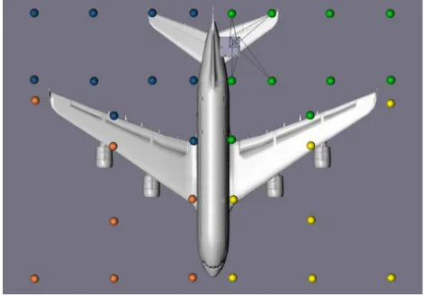
Several solutions are proposed which have been inspired from the experiences of part-ners in the CableBOT project. In the first approach (Fig. 1.24), several CDPRs are used to cover the airplane body (at least 4 CDPRs). Possible locations to place the cable exit points of each CDPR can be set on top of the airplane body or on the ground. The geometric structure of the CDPRs can be reconfigured by switching the cables at the beginning of each task.
In a second approach, the winches can move along rails preferably positioned on the ceiling as shown in Fig. 1.25. Four CDPRs can be used to work in four separate sections according to the shape of the airplane, and to satisfy the constraint of having no cable running above the airplane due to strict requirements in some maintenance tasks (e.g. in painting tasks, the above areas of the airplane fuselage must be clean, having cables across these areas may bring dust and unwanted substances falling down on the painting sur-face). The main drawbacks of this solution are that the cable lengths might be quite long to span a large area and the mobile platform has to move near the boundary of the workspace. Furthermore, the building has to sustain large lateral forces exerted by the cables.
1.4. ON THE USE OF LARGE-DIMENSION RECONFIGURABLE CDPRS IN TWO
TARGETED INDUSTRIAL APPLICATIONS 23
In a third scenario (Fig. 1.26), the winches of each CDPR can move freely on two over-head bridge cranes. These cranes can move along other perpendicular rails directed along the airplane main dimension (on the right-side of the figure). This solution is quite flexible since we can find optimal way to update the positions of the winches to achieve appro-priate performances. On the left-side of the figure, a more complicated implementation is proposed. The directions of the rails can be oriented differently. But, in order to adapt the system to various airplanes, these rail directions have probably to be changed which makes this second solution difficult to implement and costly.
Figure 1.24: Using grid of winches to reconfigure CDPRs in 4 sections over the airplane body
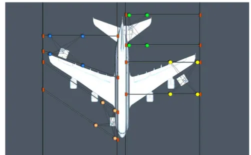
Note that in all scenarios, it is possible to have variable implementations in order to change each CDPR property (e.g. from under constrained type into fully constrained type), thereby providing more flexible solutions. Fig. 1.27 shows a solutions where there are avail-able winches on the ground. Each suspended CDPR can then be transformed into a fully constrained CDPR.
Figure 1.26: All pairs of winches can move on reconfigurable rails (this solution is similar to factory workshop use case)
Figure 1.27: Fully constrained CDPRs: 4 winches can move on the rails on top of the airplane body, the other 4 winches can be switched among a grid of winches on the ground
1.4. ON THE USE OF LARGE-DIMENSION RECONFIGURABLE CDPRS IN TWO
TARGETED INDUSTRIAL APPLICATIONS 25
PREFERRED SCENARIOS
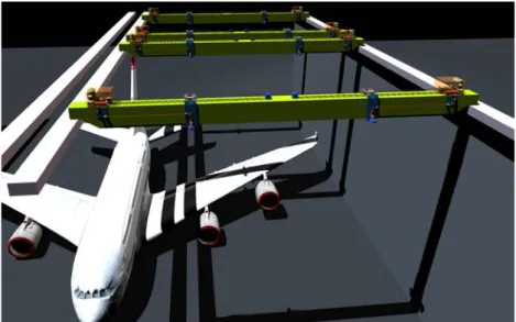
Fig. 1.28 and 1.29 show a preferred scenario of using 4 reconfigurable CDPRs in an airplane maintenance workshop. This solution is similar to the ones proposed in factory workshop use case. The cable exit points move by pairs on the two overhead bridge cranes which can slide along parallel rails attached to the side walls of the workshop. In this setup, all four CDPRs can simultaneously perform required tasks in four given sections of the workshop.
Figure 1.28: Solution of using 4 CDPRs in an airplane maintenance workshop: covered areas
Figure 1.29: Solution of using 4 CDPRs in an airplane maintenance workshop: perspective view
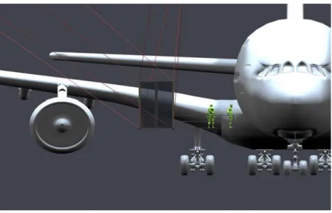
To overcome the difficulty of reaching all the parts of the airplane body, suitable means are required, e.g. by adjusting the design of the mobile platform to increase its reachable range to access the lower parts of the airplane body. A possible solution (Fig. 1.30 and 1.31) is to keep the shape of the mobile platform similar to that of telescopic platforms used in conventional methods (Fig. 1.23). It is then required to find suitable locations for the cable anchor points that connect the cables to the CDPR platform in order to have a good counter-balance design that could maintain the stability of the platform taking into account the presence of workers working onboard.
Figure 1.30: Modified mobile platform: perspective view
Figure 1.31: Modified mobile platform: elongate the platform working area to reach the lower part of airplane body
1.5. CONTRIBUTIONS AND CONTENT OF THE THESIS 27
1.5 Contributions and Content of the Thesis
The main objective of this thesis being to develop a framework for reconfigurable CD-PRs, the first step has been presented in Section 1.4 in which several general architectures of reconfigurable CDPRs were proposed (some of the solutions were inspired by the experi-ences from the partners in the CableBOT project). In the following chapters, I will detail my two main contributions. The first achievement is an extensive study on the CDPR model-ing, including cable models suitable for large-dimension CDPRs. The second contribution consists of systematic procedures to deal with the reconfiguration (planning) problem of a family of reconfigurable CDPRs.
Chapter 2 presents the state of the art of CDPR kinematic, dynamic and elastostatic modeling. The inverse kinematics problem, the tension distribution problem and the derivation of the stiffness matrix of general 6-DOF CDPRs are addressed in detail. Several collision detection algorithms are also presented. All of these are useful for design, motion planning and control of reconfigurable CDPRs. The solutions of the inverse kinematics and tension distribution problems are used in the robot control system. In the design or plan-ning phase, tension distribution solutions are used to verify wrench feasibility conditions guaranteeing that all cables could remain tensed while not exceeding maximum allowed cable tension values. Collision detection algorithms are needed to verify that the CDPR workspace is collision free, especially for spatial CDPRs with a large number of cables.
Chapter 3 details the extended modeling of CDPRs. The corresponding models con-sider most of the factors that could affect the CDPR performances such as: cable char-acteristics (cable mass, cable elasticity), thermal effect (the change of environment tem-perature), friction (between cables and pulleys, in the gear box of the winch...) and the influence of pulley kinematics. The CoGiRo prototype2, an 8-cable large-dimension sus-pended CDPR, is used to illustrate the procedure in simulations and experiments. Our study shows that one should take into account those factors in order to improve the CDPR performance, especially its positioning accuracy.
Finally, Chapter 4 deals with the CDPR reconfiguration problem. In the scope of this thesis, we consider the reconfiguration problem as a general nonlinear optimization prob-lem. The reconfigurability of the CDPR corresponds to the ability to adjust the positions of the cable exit points, thereby enabling the CDPR to adapt its performances. The fo-cus of our study is on the methods to formulate the optimization problems into standard forms. It allows one to use any available (suitable) optimization software to find the op-timal reconfiguration solutions. Two case studies are discussed. In the first case study,
the CDPR reconfiguration problem is considered as a single-objective optimization prob-lem. A systematic procedure is proposed to solve this problem using fast optimization tools (e.g. gradient-based optimization) which enable real-time capable resolutions. It can be implemented both in offline and online CDPR operation modes. However, optimizing only one objective function to derive the CDPR reconfiguration solution may be not satis-factory enough in some cases. Thus, in the second case study, we consider the CDPR re-configuration problem as a multi-objective optimization in which the solution is found by optimizing several performance indices. A systematic procedure is presented to formulate this problem and transform it into standard forms that could be solved with readily avail-able optimization softwares. The proposed approach offers more reliavail-able motion planning solutions for the CDPR while efficiently dealing with the tradeoff between several criteria.
C
H A P T E R2
P
RELIMINARIES
Summary
2.1 General CDPR Modeling . . . 30 2.2 Cable Modeling . . . 32 2.3 The Tension Distribution Problem . . . 41 2.4 Stiffness Matrix of CDPRs . . . 43 2.5 On the Collision Detection Problems . . . 47This chapter is dedicated to the modeling of a general CDPR. Several aspects, funda-mental to the design, motion planning and control of CDPRs, are presented. The well-known CDPR inverse kinetostatic problem (IKP) is discussed in Section 2.1. Section 2.2 presents the procedure to derive a simplified cable model which takes into account the cable mass and longitudinal elasticity. Section 2.3 briefly reminds the cable tension distri-bution problem of a general 6-DOF CDPR. The derivation of the stiffness matrix of a CDPR is then detailed in Section 2.4. This derivation is based on the elastic catenary cable model. Lastly, Section 2.5 discusses collision detection issues for CDPRs.
2.1 General CDPR Modeling
2.1.1 Kinetostatic Modeling
Fig. 2.1 shows a general m-cable CDPR where Ai and Bi (i= 1,..,m) are the cable i exit
point and anchor point, respectively. FBi
fbi x, fbi y, fbi z
andτbi are the force and tension
in cable i at anchor point Bi
xbi, ybi, zbi
. All the terms are expressed in the base frame of the robot (global frame).
The modeling of a CDPR, in general, is based on a cable model and the CDPR
equilib-rium equations. In [80], Irvine presents the well-known cable model known as the elastic catenary which takes the cable mass and elasticity into account. In [81], a cable catenary
model in 3D Cartesian space is introduced. A fully 3D cable catenary model can be ex-pressed in the following form:
xbi= f1i L0i, fbi x, fbi y, fbi z (2.1a) ybi= f2i L0i, fbi x, fbi y, fbi z (2.1b) zbi= f3i L0i, fbi x, fbi y, fbi z (2.1c)
where L0i is the cable i unstrained length and fj i are non-linear functions [81].
In the case of inverse kinematic problem, given the pose of the mobile platform then in (2.1), the coordinates of point Bi are determined. One need to find four unknown terms
(which are the cable unstrained length and cable force components). The number of un-known variables is larger than the number of equations, thus it is necessary to consider the
massless cables hefty cables A1 A2 Am B1 B2 Bm b1 bm u1 um FBm FB1 Bi i Bi bi bi F F F τ = = u
2.1. GENERAL CDPR MODELING 31
equilibrium equations of the mobile platform:
Wτb+ fe= 0 (2.2)
subject to:
τmin≤ τbi≤ τmax¡i = 1,m¢ (2.3)
and where W = " u1 u2 · · · um Rb1× u1 Rb2× u2 · · · Rbm× um # τb = h τb1 τb2 · · · τbm iT fe = h fx fy fz mx my mz iT
Here, feis the wrench applied by the cables on the mobile platform, biis the position vector
of the anchor point Bi with respect to the origin of the mobile platform frame with origin Op and ui is the unit vector directing the cable force FBi. τminandτmaxare the minimum
and maximum admissible limits on the cable tensions. R is the rotation matrix from the global frame to the mobile platform frame.
The condition (2.3) is to ensure the cables are always under tension (τmin≥ 0) and the
cable tensions are smaller than a maximum acceptable value. These conditions on the cable tensions make a CDPR different from a rigid-link parallel manipulator. The inequatl-ities in (2.3) introduce complexity in solving the kinetostatic problems of CDPRs (inverse kinematic and tension distribution problems).
2.1.2 Dynamic Modeling
In this thesis, only the dynamics of the mobile platform is considered. Cable dynamics is neglected. The center of mass of the mobile platform is denoted C . The coordinates of C in the mobile platform frame < Op> are (xc yc zc). We consider that the mobile platform
moves with acceleration ap (of the origin Op), angular velocityω and angular acceleration
α. Here, the dynamics of the cables and the dynamics of the systems that drive the cable
exit points, if any, are neglected.
According to Newton-Euler equations, one can write the equation of motions of the mobile platform as follows:
" F Mp # + " mpG d × mpG # + W τb= 0 (2.4)
where F and Mp are the inertia forces and moments acting on the mobile platform, and mp is the total mass of the mobile platform. W andτb are defined in (2.30), G = (0 0 g )
with g = 9.81m/s2, and d = R ·O−−−→pC is the projection of vector−−−→OpC onto the global frame.
Because the center of mass C is distinct from Op, we have:
F = mp£ap+ α × d + ω × (ω × d)
¤
(2.5)
Mp = mpd × ap+ Ipα + ω × ¡Ipω¢ (2.6)
where Ip is the moment of inertia about the reference point Op of the mobile platform
expressed in the global frame:
Ip= R IcRT+ mp £¡dTd¢ · 13×3− d dT
¤
(2.7)
Here, Icis the polar moment of inertia (or matrix of inertia about the center of mass) of the
mobile platform and 13×3is the identity matrix.
Depending on the context, either static modeling or dynamic modeling of the CDPR will be used. In fact, for control or motion planning, either (2.2) or else (2.4) will be used to compute the inverse kinematics solution (the cable unstrained lengths) and the desired cable tensions.
2.2 Cable Modeling
According to the previous section, to solve the inverse kinematics problem of a m-cable 6-DOF CDPR, there are 4m unknown terms¡L0i, fbi x, fbi y, fbi z¢ (i = 1,..,m) and a total of
3m + 6 equations, including 3m cable equations (2.1) and the equilibrium equations (2.2) or (2.4). We need numerical methods to solve the inverse kinematics problem as well as the tension distribution problem since these two problems are non-linear and coupled together [24]. It becomes more complicated especially for the case of redundantly actuated CDPRs driven by more than 6 cables. However, such methods are usually time consuming and may be impractical in real-time control schemes. Simpler cable models are thus of interest to reduce the complexity of the problem.
Different approaches to avoid using the catenary cable model in modeling CDPRs have been proposed. In many previous studies on CDPRs, all cables have been considered mass-less. For robots of reasonable size and carrying light payloads massless cable models can be used, but for large-dimension robots or for robots that carry heavy payloads, the cable mass may have to be taken into account [23]. In [80], Irvine presents a parabolic cable
2.2. CABLE MODELING 33
model. This cable model is valid if the sagging of the cable is small enough. However, the suggested validity condition is not explicitly derived. In [23], the parabolic hefty cable model is reintroduced in a simplified static analysis of large-dimension CDPRs which gives a linear relation between the cable horizontal and vertical force components. This relation helps to transform the cable tension distribution problem into one that is similar in form to the case of CDPRs with massless cables, from which one can apply advanced methods to find the cable tensions such as [18, 19, 32]. A nonlinear version of the relation between the cable horizontal and vertical force components is derived in [82] based on the catenary model. Knowing the cable tension, the cable unstrained length can be computed. In [24], Kozak gives an expression for the cable unstrained length, which takes into account the cable mass but without considering the cable elasticity. Later, an approximation of that expression is obtained by Rui Yao et al. in [83].
In this section, we shall give a discussion on the simplification of cable model as well as the determination of the cable unstrained length (solution to the inverse kinematics of a CDPR) as published in [69].
2.2.1 Cable Profile
Let us consider a steel cable that has unstrained length L0(m), self-weight w (N /m),
elastic modulus E (P a) and cable cross-section area A0(m2).
Fig. 2.2 shows the relevant coordinates and parameters of a cable lying in a vertical plane in static equilibrium. The cable is fixed between two end-points A (xLa, zLa) and
M(xL, zL; p; s) A B zL xL FB fLbx fLbz β g ( w , E, A0 ) L0
B (xLb, zLb)1. All the coordinates are in the local frame attached to the vertical plane
con-taining the cable. The term∆L represents the strain of the cable.
A point M along the strained cable has Cartesian coordinates xLand zL. The variable p
represents the strained length of the cable segment as measured from the end-point A of the cable to the point M . The variable s will be used to denote the unstrained length of the same cable segment. In Fig.2.2, the origin of the local frame will be placed at the end-point
A. Thus, the variable s lies in the range: 0 ≤ s ≤ L0with M (s = 0) ≡ A and M(s = L0) ≡ B.
The well-known catenary equations can be written as follows [80]:
xL(s) = xLb+ fLbx(s − L0) E A0 +fLbx w ln ·τ s+ fLbz+ w(s − L0) τb+ fLbz ¸ (2.8a) zL(s) = zLb+ fLbz(s − L0) E A0 +w (s − L0) 2 2E A0 + 1 w(τs− τb) (2.8b)
where fLbx, fLbz are the cable horizontal and vertical force components at point B and τs,τbare the tensions in the cable at point M and B , respectively:
τs= q fLbx2 +£ fLbz+ w(s − L0) ¤2 (2.9) τb= q fLbx2 + fLbz2 (2.10)
The shape of the cable must satisfy the geometric constraint: µ d xL d p ¶2 + µ d zL d p ¶2 = 1 (2.11) which implies: d p d xL = s 1 + µ d zL d xL ¶2 (2.12)
At point M , the force balance for the segment of the cable between points M and B can be written as follows: τs µ d xL d p ¶ = fLbx (2.13a) τs µ d zL d p ¶ = fLbz+ w(s − L0) (2.13b)
The cable tension at point M is considered to satisfy Hooke’s law:
τs= E A0 µ d p d s − 1 ¶ (2.14)
2.2. CABLE MODELING 35
The relationship between coordinates xLand zL which does not depend explicitly on the
variable s can be derived from (2.12), (2.13) and (2.14):
d2zL d xL2 = w fLbx · E A0 E A0+ τs· s 1 + µ d zL d xL ¶2 (2.15)
Let us assume thatτs¿ E A0. Then, the cable elasticity has a very little influence on the
cable shape since (2.15) can be reduced to the simpler expression:
d2zL d xL2 = w fLbx · s 1 + µ d zL d xL ¶2 (2.16)
The solution of (2.16) is:
zL(xL) = fLbx w cosh µ w fLbx xL+C1 ¶ +C2 (2.17)
which must satisfy the following boundary conditions:
zL(xLa) = zLa (2.18a)
zL(xLb) = zLb (2.18b)
As the origin of the local cable frame has been chosen at point A, xLa= 0 and zLa= 0, then:
C2= − 1 µcosh (C1) (2.19) zLb= 1 µ£cosh¡µxLb+C1¢ − cosh(C1) ¤ (2.20) where µ = w fLbx (2.21)
The term C1can be found by solving (2.20)
C1= ln q µ2z2 Lb+ eµxLb+ e−µxLb− 2 + µzLb eµxLb− 1 (2.22)
The conditions to achieve (2.22) are:
xLb> 0 (2.23a)