HAL Id: hal-01233654
https://hal.archives-ouvertes.fr/hal-01233654
Submitted on 25 Nov 2015
HAL is a multi-disciplinary open access
archive for the deposit and dissemination of
sci-entific research documents, whether they are
pub-lished or not. The documents may come from
teaching and research institutions in France or
abroad, or from public or private research centers.
L’archive ouverte pluridisciplinaire HAL, est
destinée au dépôt et à la diffusion de documents
scientifiques de niveau recherche, publiés ou non,
émanant des établissements d’enseignement et de
recherche français ou étrangers, des laboratoires
publics ou privés.
Small 3D Array Design Using Superdirective Antennas
Abdullah Haskou, Sylvain Collardey, Ala Sharaiha
To cite this version:
Abdullah Haskou, Sylvain Collardey, Ala Sharaiha. Small 3D Array Design Using Superdirective
Antennas. Loughborough Antennas and Propagation Conference, Nov 2015, Loughborough, United
Kingdom. �10.1109/LAPC.2015.7366122�. �hal-01233654�
Small 3D Array Design Using Superdirective
Antennas
Abdullah Haskou, Sylvain Collardey, and Ala Sharaiha,
IETR UMR CNRS 6164- Université de Rennes 1, Rennes, France
[email protected], [email protected], [email protected]
Abstract—In this paper, we present a compact broadside
superdirective antenna array based on a planar parasitic su-perdirective unit-element. The array is designed for 905M Hz frequency band, its dimensions are 200× 54 × 24mm3(0.6λ× 0.16λ× 0.07λ), and it presents a directivity of 9.2dBi and radiation efficiency of 8.3%. Integrating the initial parasitic array in a PCB of 110× 70mm2, the array total dimensions are 200× 110 × 70mm3(0.58λ× 0.32λ × 0.2λ), and it presents a directivity of 9.8dBi and radiation efficiency of 64%.
Keywords—ESA, compact, end-fire, broadside, superdirectivity, parasitic element
I. INTRODUCTION
Electrically Small Antennas (ESAs) are very attractive for emerging multi-band wireless technologies. These an-tennas have narrow bandwidths, low efficiencies and quasi-omnidirectional radiation patterns. However, for some RF pointing devices, in addiction to compactness, high directivities are required. In such a case, superdirective ESAs, where the array elements are put very closely together, may be an acceptable solution.
Since the pioneer works of I. Uzkov [1] and of E. N. Gilbert and S. P. Morgan [2], an important research was done on su-perdirective arrays [3]-[9]. Early works were mainly about the design of wire-antenna arrays [3]-[4]. A three-element fully-driven monopole-based array was presented in [3]. O’Donnell and Yaghjian showed that, in wire-type arrays, the parasitic (shorted) array presents approximately the same directivity as the fully-driven one [4]. Furthermore, Yaghjian et al. showed that in this type of arrays not only superdirectivity is feasible but also supergain [5]. An important chapter summarizing early works on superdirective arrays is presented in [6]. Recently, multiple planar parasitic superdirective ESAs were presented [7]-[9]. In this paper, we propose using such arrays as unit-elements to design compact classical 3D broadside arrays.1
II. SIMULATIONS ANDRESULTS
In [11] we presented a two-element parasitic superdirective array with an inter-element distance of 0.1λ and total dimen-sions of 54× 24mm2. It presents a simulated (HFSS [12]) maximum total directivity of 7dBi and radiation efficiency of 7.1%. The Half-Power Beamwidth (HPBW) in horizontal and vertical planes (XOY and YOZ) are respectively 110o
and 80o and the Front to Back Ratio (FBR) is equal to 9dB.
Two elements of this array are stacked with an inter-element
1This work was done with the funding of the French National Research
Agency as part of the project "SOCRATE" and the support of the "Images et Reseaux" cluster of Brittany region, France.
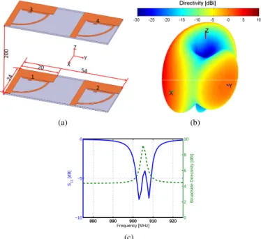
distance of 200mm(0.6λ) to design a 3D broadside array. Fig. 1(a) shows the array geometry and dimensions in mm, where elements 1 and 3 are excited with equal power, while elements 2 and 4 are loaded with a capacitor of 5.1pF (refer to [11] for more details on the loads calculation method). The antenna simulated 3D total directivity radiation pattern given in Fig. 1(b) reveals a directive pattern with a maximum total directivity of 9.2dBi toward the broadside direction (Yo). The HPBW in horizontal and vertical planes are now respectively 110◦ and 45◦, FBR is 8.6dB and Side Lobe Level (SLL) is
−13dBi. Furthermore, Fig. 1(c) shows that antenna’s
broad-side total directivity (D(θ=90o,ϕ=270o)) is maximal around the resonance frequency of 905M Hz (since the two elements are identical we are only showing the reflection coefficient of one of them). Finally, the antenna presents a simulated radiation efficiency of 8.3%. Comparing with the initial end-fire array, it can be noticed that the total directivity is increased by 2.2dB, the horizontal HPBW is the same, while the vertical one is divided by 1.8. As for antenna’s FBR and radiation efficiency, they are approximately the same as the initial end-fire’s ones.
(a) (b) 880 890 900 910 920 −10 −5 0 Frequency [MHz] S11 [dB] 880 890 900 910 920 0 2 4 6 8 10
Broadside Directivity [dBi]
(c)
Fig. 1. Broadside array geometry and simulated parameters. (a) Geometry and dimensions, (b) 3D total directivity radiation pattern, and (c) input reflection coefficient magnitude and end-fire total directivity.
The initial end-fire array was integrated in a PCB with total dimensions of 110× 70mm2 and optimized for operating at
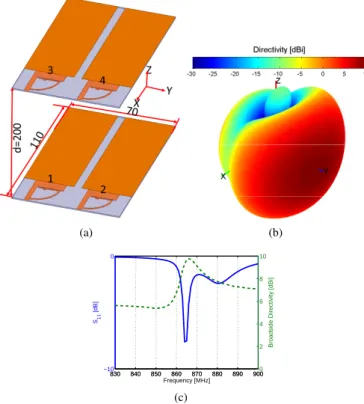
866M Hz frequency band. The integration in the PCB was done via a study similar to the one presented in [14]. This antenna presents a superdirective pattern with a maximum total directivity of 7.2dBi. The HPBW in horizontal and vertical planes are respectively 74◦ and 110◦, and the FBR is 8.4dB. The antenna has a radiation efficiency of 62%. Again, two elements of this array are stacked with an inter-element distance of 200mm to form a 3D broadside array as shown in Fig. 2(a). Elements 2 and 4 are excited with equal power, while elements 1 and 3 are loaded with an inductor of 4.35nH. As it can be seen from the antenna simulated 3D total directivity radiation pattern given in Fig. 2(b), the antenna is superdirective with a maximum total directivity of 9.8dBi. The HPBW in horizontal and vertical planes are respectively 76◦ and 45◦, FBR is 8.4dB and SLL is−10.6dBi. Fig. 2(c) shows that antenna’s broadside total directivity (D(θ=90o,ϕ=90o)) is
also maximal around the resonance frequency of 866M Hz. Finally, the antenna presents a simulated radiation efficiency of 64%. Comparing with the initial end-fire array, it can be noticed that the total directivity is increased by 2.6dB. The horizontal HPBW is almost the same, while the vertical one is divided by 2.4. As for antenna’s FBR and radiation efficiency, they are approximately the same as the initial end-fire’s ones.
(a) (b) 830 840 850 860 870 880 890 900 −10 0 Frequency [MHz] S11 [dB] 830 840 850 860 870 880 890 9000 2 4 6 8 10
Broadside Directivity [dBi]
(c)
Fig. 2. Broadside array on a PCB geometry and simulated parameters. (a)
Geometry and dimensions, (b) 3D total directivity radiation pattern, and (c) input reflection coefficient magnitude and end-fire total directivity.
III. DISTANCEEFFECT
To study the effect of the distance (d) on the array performance, we vary this distance in the PCB integrated array from 0.01λ to λ while monitoring antenna’s input reflection coefficient, total directivity and radiation efficiency. Fig. 3(a) shows the array simulated input reflection coefficient magnitude in dB as a function of the distance. The figure
shows that for d = 0.01λ the array resonance frequency is shifted to 969M Hz. This is due to the high mutual coupling that appears as a decrease in the array electrical length. As the distance increases the array resonance frequency decreases to converge to the one of the unit-elements. Fig. 3(b) shows the array simulated maximum total directivity and radiation efficiency as a function of the distance. The figure shows that for very small distances, the antenna’s efficiency is maximal and as the distance increases the efficiency decreases. This is mainly due to the the lost of superdirectivity for very small distances (superdirectivity is achieved by current opposition on the two elements which reduces the antenna efficiency). Fig. 4 shows the array simulated 2D total directivity radiation patterns at the design frequency (866M Hz) as a function of the distance. The figure shows that for very small distances, the array directive pattern is lost and the array has a quasi-omnidirectional radiation pattern. This is also due to the high coupling effect that makes the applied loads unsuitable for having directive unit-elements. As the distance increases, the achieved directivity increases till 0.8λ when it starts decreasing again. Furthermore, as expected, for distances greater than 0.5λ side lobes appear in the vertical plane and as the distance increases SLL also increases.
800 850 900 950 1000 −14 −12 −10 −8 −6 −4 −2 0 Frequency [MHz] S11 [dB] 0.01λ 0.3λ 0.6λ 0.9λ (a) 0 0.2 0.4 0.6 0.8 1 60 65 70 75 80 85 90 ra d [% ] d/ 0 0.2 0.4 0.6 0.8 10 2 4 6 8 10 12 Dma x [d Bi ] (b)
Fig. 3. Broadside array on a PCB simulated parameters as a function of the
distance. (a) input reflection coefficient magnitude, and (b) maximum total directivity and radiation efficiency.
−30 −20 −10 0 10 30 210 60 240 90 270 120 300 150 330 180 0 φ [°] Directivity [dBi] 0.01λ 0.3λ 0.6λ 0.9λ (a) −30 −20 −10 0 10 30 210 60 240 90 270 120 300 150 330 180 0 θ [°] Directivity [dBi] 0.01λ 0.3λ 0.6λ 0.9λ (b)
Fig. 4. Broadside array on a PCB simulated 2D total directivity radiation
patterns as a function of the distance. (a) Horizontal plane and (b) vertical plane.
IV. RESULTSVALIDATION VIAMEASUREMENTS
In [13], it was shown that the measured parameters of the end-fire array on a PCB are in a good agreement with the simulated ones. Fig. 5(a) shows a photograph of the fabricated
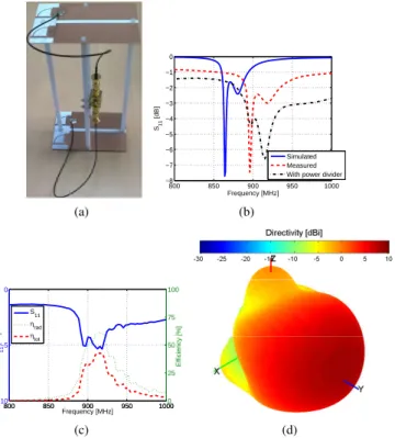
prototype of the broadside array on a PCB and Fig. 5(b) shows its measured input reflection coefficient magnitude. The measured resonance frequency is 896M Hz (a frequency shift of 3.5%). This shift is probably due to the UFL cable effect, the dispersion of the commercial SMD loads, and the modi-fications in the antenna geometry for fixing the two elements together. The higher losses in measurements can be attributed to the losses in the UFL cable and the SMA connections. The measured radiation efficiency in a reverberation chamber [15] is about 60.5% (Fig. 5(c)). The antenna far-field radiation pattern was measured in SATIMO stargate (SG 32) near-field measurement system. The measured 3D and 2D total directivity radiation patterns at the resonance frequency are given in Fig. 5(d) and Fig. 6. The measured pattern in the main-beam direction is in acceptable agreement with the simulated one. A considerable divergence is noticed in the backward direction. This divergence may be due to the feeding system, and the measuring system and environment. The measured directivity is about 8.6dBi and the HPBW in horizontal and vertical planes are respectively 56◦ and 84◦.
(a) 800 850 900 950 1000 −8 −7 −6 −5 −4 −3 −2 −1 0 Frequency [MHz] S11 [dB] Simulated Measured With power divider
(b) 800 850 900 950 1000 −10 −5 0 S11 [dB] Frequency [MHz] 800 850 900 950 10000 25 50 75 100 Efficiency [%] S11 ηrad ηtot (c) (d)
Fig. 5. Broadside array on a PCB prototype and measured parameters. (a)
Fabricated prototype, (b) input reflection coefficient magnitude, (c) efficiency and (d) 3D total directivity radiation pattern.
V. CONCLUSION
In this paper, we presented a compact broadside array based on a planar parasitic superdirective unit-element. The array dimensions were 0.6λ×0.16λ×0.07λ, and it presented a total directivity of 9.2dBi. Integrating the unit-elements in a PCB of 110×70mm2, the array dimensions were 0.58λ×0.32λ×0.2λ, and it presented a total directivity of 9.8dBi and radiation efficiency of 64%. By using a 2× 2 superdirective elements, a broadside array of 0.58λ× 0.58λ × 0.2λ presenting a total directivity of 11.4dBi and radiation efficiency of 72.3% can be achieved. −30 −20 −10 0 10 30 210 60 240 90 270 120 300 150 330 180 0 φ [°] Directivity [dBi] Simulated Measured (a) −30 −20 −10 0 10 30 210 60 240 90 270 120 300 150 330 180 0 θ [°] Directivity [dBi] Simulated Measured (b)
Fig. 6. Broadside array on a PCB measure 2D total directivity radiation
patterns. (a) Horizontal plane and (b) vertical plane.
REFERENCES
[1] I. Uzkov, "An Approach to the Problem of Optimum Directive Antennae
Design", Comptes rendues (Doklady) de l’académie des sciences de l’URSS, Vol. 53, No. 1, 1946.
[2] E. N. Gilbert, and S. P. Morgan, "Optimum Design of Directive Antenna
Arrays Subject to Random Variations", Bell System Technical Journal, Vol. 34, pp. 637-663, May 1955.
[3] E. E. Altshuler, T. H. O’Donnell, A.D. Yaghjian, and S. R. Best, "A
Monopole Superdirective Array", IEEE Transactions on Antennas and Propagation, Vol. 53, No. 8, pp. 2653-2661, August 2005.
[4] T. H. O’Donnell, and A. D. Yaghjian, "Electrically Small Superdirective
Arrays Using Parasitic Elements", IEEE Antennas and Propagation Society International Symposium 2006, pp. 3111,3114, 9-14 July 2006.
[5] A. D. Yaghjian, T. H. O’Donnell, E. E. Altshuler, and S. R. Best
"Electrically Small Supergain End-Fire Arrays", Radio Science, Vol. 43, 2008.
[6] R. C. Hansen, and R. E. Collin, "Small Antenna Handbook", John Wiley
& Sons Incorporation, Hoboken, New Jersey, 2011.
[7] M. Pigeon, A. Sharaiha, and S. Collardey, "Miniature and Superdirective
Two Elements Endfire Antenna Array", 8th European Conference on Antennas and Propagation (EuCAP 2014), 6-11 April 2014.
[8] A. Haskou, A. Sharaiha, S. Collardey, M. Pigeon, and K. Mahdjoubi,
"A Design Methodology for Electrically Small Superdirective Antenna Arrays", 2014 Loughborough Antennas and Propagation Conference (LAPC 2014), 10-11 November 2014.
[9] A. Haskou, A. Clemente, A. Sharaiha, C. Delaveaud, S. Collardey, and
L. Rudant, "A Parasitic Three-Element Superdirective Electrically Small Antenna Array, Proceedings of Ninth European Conference on Antennas and Propagation (EuCAP 2015), 12-17 April 2015.
[10] B. Sentucq, A. Sharaiha, and S. Collardey, "Superdirective Compact
Parasitic Array of Metamaterial-Inspired Electrically Small Antenna", International Workshop on Antenna Technology (iWAT), pp. 269,272, 4-6 March 2013.
[11] A. Haskou, S. Collardey, and A. Sharaiha, "A Design Methodology for
Impedance-Matched Electrically Small Parasitic Superdirective Arrays", 2015 IEEE Symposium on Antennas and Propagation (APS 2015), 19-25 July, 2015.
[12] ANSYS HFSS, Pittsburg, PA 15219, USA.
[13] A. Haskou, A. Sharaiha, and S. Collardey, "On Measuring
Superdirec-tive Electrically Small Antenna Arrays", 2015 International Workshop on Antenna and Technology (iWAT 2015), 4-6 March, 2015.
[14] A. Haskou, A. Sharaiha, and S. Collardey, "Integrating Superdirective
Electrically Small Antenna Arrays in PCBs", IEEE Antennas and Wire-less Propagation Letters, doi: 10.1109/LAWP.2015.2425913.
[15] G. Le Fur, C. Lemoine, P. Besnier, A. Sharaiha, "Performances of
UWB Wheeler Cap and Reverberation Chamber to Carry Out Efficiency Measurements of Narrowband Antennas", IEEE Antennas and Wireless Propagation Letters, Vol. 8, pp.332,335, 2009.