HAL Id: hal-00125078
https://hal.archives-ouvertes.fr/hal-00125078
Submitted on 17 Jan 2007HAL is a multi-disciplinary open access archive for the deposit and dissemination of sci-entific research documents, whether they are pub-lished or not. The documents may come from teaching and research institutions in France or abroad, or from public or private research centers.
L’archive ouverte pluridisciplinaire HAL, est destinée au dépôt et à la diffusion de documents scientifiques de niveau recherche, publiés ou non, émanant des établissements d’enseignement et de recherche français ou étrangers, des laboratoires publics ou privés.
Improvement of methane storage in activated carbon
using methane hydrate
Marie-Line Zanota, Laurent Périer-Camby, Fabien Chauvy, Yves Brullé,
Jean-Michel Herri
To cite this version:
Marie-Line Zanota, Laurent Périer-Camby, Fabien Chauvy, Yves Brullé, Jean-Michel Herri. Improve-ment of methane storage in activated carbon using methane hydrate. Fifth International Conference on Gas Hydrates (ICGH 5)„ Jun 2005, Tromdheim, Norway. �hal-00125078�
IMPROVEMENT OF METHANE STORAGE IN ACTIVATED CARBON
USING METHANE HYDRATE
M.L. Zanota(1), L. Perier-Camby(1), F. Chauvy(1), Y. Brullé(2), J.M. Herri(1*)
1- Centre SPIN, Ecole des Mines de Saint Etienne, 158 Cours Fauriel, 42023 Saint Etienne Cedex 2
2- Gaz de France, Direction de la Recherche, 361 Avenue du Président Wilson, BP 33, 93211 Saint-Denis La Plaine Cedex
ABSTRACT
The methane storage capacity of dry and wetted activated carbon is evaluated at 1°C in the pressure range [1-8MPa]. The experiments emphasize the complex influence of the water content. The presence of water decreases the storage kinetics. It decreases also the storage capacity excepted in a domain of water concentration which has not been evaluated precisely but which is located in the range 30-80 % mass of water
Keywords : activated carbon, adsorption, gas storage
INTRODUCTION.
With the massive increase of the urban traffic, coupled with its large contribution to the local pollution in the city centres, natural gas appears to be a favourable alternative to gasoline and diesel. In fact, among the different fuel elements, the methane shows the best ratio H/C which allows to reduce the CO2 emissions.
More, it is a clean fuel with specially low emissions of CO, NOx and particles. As the
natural gas resources are enormous, it represents a good alternative to oil in term of energetic independence.
The improvement of the natural gas onboard storage is one of the major parameters to develop this energy. Currently, the natural gas could be stored mainly as compressed gas in pressurised tanks at very high pressure of 20 MPa which can set the engineers a problem of security. It can also be liquefied at -162°C but then requires a cryogenic tank which can hardly be envisaged for onboard applications. The last solution is to store by adsorption on activated carbon for example [1].
..(*) Corresponding author : Phone +33 4 77 42 02
92 Fax +33 4 77 49 96 94 E-mail : [email protected]
The storage capacity of the adsorption technology reaches 100 to 140(n)m3/m3 at 3.5
MPa. This value is lower than that obtained in the compressed gas technology which storage capacity is 200 (n)m3/m3 but at a higher
pressure of 20 MPa. The storage pressure of the sorption technology is only 3.5 MPa and presents two main advantages : first, it limits the compression work for the tank filling up and allows to connect directly to the existing natural gas distribution network. Secondly, at low pressure, the tank geometry can adopt various shapes in order to adjust it to the vehicle body (polymorphous tanks).
The interest of the adsorption stays only if performances are sufficiently good, i.e. if the available natural gas volume is sufficient and compatible with the city runs. This article deals with a concept that aims to increase the adsorption capacity by coupling it to a gas hydrate formation. In fact, the gas hydrate formation in the remaining free porosity after classical physi-sorption of natural gas on activated carbon should permit to increase the storage capacity [2].
METHANE HYDRATE
For pure methane, only the SI structure
is stable. The lattice parameter is 1.203 nm. It is composed of 46 water molecules arranged to
form a network of two cavities 512 and six
cavities 51262. As a result, if all the cavities are
occupied by a methane molecule, the theoretical formula of methane hydrate is CH4(H2O)5.75. In the reality, not all the cavities
are filled and the methane storage in the hydrate structure is around 170 (n)m3/m3.
Table 1 shows the equilibrium curve of methane hydrate.
T [°C] 0 1 2 4 6 8 10 12
P [MPa] 2.6 2.9 3.2 3.9 4.8 5.9 7.4 9.2 Table 1. Methane hydrate equilibrium curve (For a more complete description of the hydrate structure and of the thermodynamics, please refer to Sloan [3])
LITTERATURE STUDY
In the purpose to form these compounds to complete the classical adsorption of natural gas on activated carbon, it is strictly compulsory to previously wet the porous media. But, the pre-adsorption of water on activated carbon is known to be a disadvantage because the presence of water generally limits the methane adsorption capacities. The idea of making hydrates in the porosity to enhance the storage capacity has been firstly attempted by Kaneko [4]. He showed a considerable improvement of the methane storage capacity of wetted activated carbon. He assigned this behaviour to the complementary methane hydrate formation. His experimental results has to be considered carefully because the experimental conditions which was applied (low pressure, ambient temperature) are very far from the classical conditions at which the methane hydrates could form in bulk conditions (see table 1). The concept was then tested and confirmed by Miyawaki [5] but the real experimental proof was published by Zhou [6,7]. He presents the influence of water on the storage of methane at pressures from 0.1 to 10 MPa and temperatures from 0 to 8°C. At pressure lower than 4 MPa, Zhou [6] observed a classical result : the presence of water decreases the storage capacities. But for sufficient water quantities and higher pressures, he observed an inversion of the tendency : the higher the water content, the higher the storage capacity.
In this article we give additional proofs showing the influence of water at low and high pressure. We give experimental evidences of
the existence of methane hydrates in the activated carbon porosity and that their formation allows to increase the methane storage capacity in comparison to pure adsorption on dry activated carbon in the same conditions of pressure and temperature. We also show that (P,T) conditions of methane storage and release by adsorption associated to the hydrate formation are influenced by the pore size distribution of the activated carbon. We show that the quantity of water pre-sorbed at the carbon surface is a crucial parameter on the storage capacity.
SAMPLE CHARACTERISATION
We present in this study results concerning two commercial activated carbons whose precursor is lingo-cellulose (They are denominated A and B). The porous texture characterisation was obtained by interpretation of physical sorption isotherms of nitrogen at 77K. The mesopore and micropore size distribution has been determined respectively by the BJH method and the Brunauer method. This last method is based on the exploitation of the t diagram, and requires the construction of a particular law giving the t parameter as a function of ρ/ρ0. The t parameter is calculated
from experiments on a non porous model sample exhibiting a similar surface chemistry. In this study, a black coal has been taken for reference.
Table 2 shows the characterisation of activated carbon A and B.
sample Mesoporous diameter (Å) Microporous diameter (Å) Surface t (m2/g)
Mesoporous volume
(cm3/g)
A 35< <45 < 8 1203 0.841
B <150 <12 967 0.647
Tableau 2.Activated carbon characteristics
EXPERIMENTS
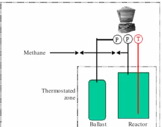
Experimental device
The set up is composed of a pressurised tank and a ballast reference which operating pressure is up to 10 MPa. The pressurised tank is temperature controlled in the range [-25°C, +80°C] by mean of a cooling jacket. The ballast is directly located into the cooling bath of the thermostat. The pressurised tank is
equipped with two sapphire windows (15 cm high, 1.5 cm wide) which allows us to look at the texture of the activated carbon during the methane hydrate crystallization. The total volume of the system is 2.6 litres (including ballast, pressurised tank and pipelines). A Pt
100 temperature probe monitors the
temperature in the activated carbon bed. A Labview program saves continuously the pressure of the pressurised tank and of the ballast, and the temperature.
Ballast Methane
Reactor Thermostated
zone
Figure 1. experimental device
Operating Protocol
Activated carbon samples are
previously heated and dried during 24 hours in a furnace at 140°C under primary vacuum. Then they are weighed to determine the mass of the dry carbon. This mass is used to calculate the number of moles of methane stored by kg of carbon.
The wetting of the carbon is done by pouring directly the liquid water in the bed under manual mixing. The wetted carbon are then weighed before the adsorption study. The quantity of water poured in the activated carbon is given in weight percentage of the dry carbon mass.
The methane storage capacity is measured by a differential method. The ballast is first filled and its pressure is measured to determine the total number of methane contained inside. Then, the connecting valve between the ballast and the reactor is opened. The temperature increases in the carbon bed due to gas compression, gas adsorption and gas hydrate crystallisation. After a while, the temperature reaches its equilibrium value imposed by the cooling jacket and then the
pressure is measured. The knowledge of the volume of the ballast and of the pressurised tank plus the determination of the final equilibrium pressure gives the total amount of methane which has been stored by the activated carbon. The term storing describes the gas
adsorption and/or the gas hydrate
crystallisation.
We studied pressure between 1 to 8 MPa in order to construct the isotherm of
methane sequestration. Temperature is
maintained constant at a value of 1°C. The inverse procedure has been used to study the release of the activated carbon bed. The pressurised tank containing the activated carbon bed is emptied by filling back the ballast and the final equilibrium pressure is measured to calculate the total amount of methane which has been released.
RESULTS AND DISCUSSIONS
methane storage
Sorption isotherms (1°C) of the sample B is presented on figure 2 as a function of the pressure up to 6 MPa, and as a function of the %mass of the water which has been previously
incorporated to the dry activated carbon (from 0 to 32.6 %mass). The results are consistent with
the literature [8] showing the negative impact of the water : the more the water quantity, the less the methane storage capacity. For sample A, this tendency has also been observed.
Figure 2. Effect of water content on the storage of methane in activated carbon B at 1°C It is interesting to note that the dry carbons which have been tested can be compared to the sample NC58 tested by Perrin et al [13] from the point of view of the massic methane uptakes. Their work must be mentioned here because they evaluated the massic methane uptakes of 5 different activated carbon in the
0 2 4 6 8 10 12 14 0 1 2 3 4 5 6 7 Pressure (MPa) A m ou nt o f C H 4 st o re d (m ol /k g d ry c ar b on ) … . dry carbon moiseture added 5.70 w% moiseture added 13.13 w% moiseture added 32.60 w% Amount of water Amount of water Amount of water
same pressure than us. They compared their results with 50 % mass wetted samples. They observed that the methane uptake is dramatically decreased in the presence of 100 % water mass. This is coherent with our results. But, for higher pressures, and higher water concentration, the tendency is inversed. The isotherm curves present an inflection point and an sudden increase of the storage capacity. The figure 3 presents the storage capacity on sample B for pre-sorbed water quantities higher to 30% mass and pressures up to 8 MPa. At a
water content of 32.6% mass, the storage
isotherm presents an inflexion point at a pressure of 6-6.5 MPa but it is not enough to increase notably the storage capacity. This inflexion point is more sensitive for water content of 73%mass and appears at lower
pressure of 3-3.5 MPa. The storage capacity reaches the performance of the dry activated carbon at a pressure of 6 MPa and higher. For higher concentration of 93%mass of water, the
storage performances remains at a very low value.
In first analysis, it appears that the methane storage capacity is very sensitive to the water content and that an optimum exists. The value
ot the optimum has not been looked for
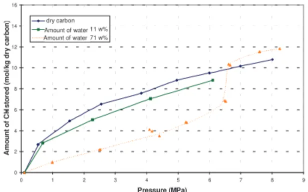
Figure 3. Effect of water content on the storage of methane in activated carbon sample B at 1°C This analysis is comforted by the experiments performed on sample A which exhibits the same behaviour (figure 4). The sorption capacities according to the pressure and for different quantities of water present an maximum at water concentration of 71 %mass.
More, in such a condition, the storage capacity of the wet carbon becomes higher than for the dry carbon for pressures higher than 6-6.5 MPa (increase of about 10% the storage capacity).
This increase can be attributed to the hydrate formation in the carbon sample for several reasons. First, the applied conditions (60 bar and 1°C) are favourable to the hydrate formation since the theoretical pressure of formation of methane hydrate in bulk condition at 1°C is 2.9 MPa. Secondly, the visual observation through reactor sapphire windows allows us the direct observation of the hydrate crystals at the surface of the activated carbon. Lastly, the sudden increase of the methane storage capacity is accompanied with a sudden increase of the temperature in the carbon bed. This behaviour is generally associated to the hydrates formation that is a exothermic crystallisation and that fixes methane.
Figure 4. Effect of water content on the storage of methane in activated carbon sample A at 1°C
6.2 Methane release
The final objective of the end user is not only the methane storage capacity but particularly the methane release capacity. In order to quantify the release capacity, the figure 5 and 6 shows the isotherm of storage and release at a temperature of 1°C for samples A and B. (Here the classical term of adsorption and desorption are not appropriated because the adsorption is accompanied with an hydrate formation). 0 2 4 6 8 10 12 14 16 0 1 2 3 4 5 6 7 8 9 Pressure (MPa) A m ou nt o f C H 4 st or ed (m ol /k g dr y ca rb on )… .. Dry carbon Charging Discharging 0 2 4 6 8 10 12 14 16 0 1 2 3 4 5 6 7 8 9 Pressure (MPa) A m ou nt o f C H 4 st or ed (m ol /k g dr y ca rb on ). … dry carbon moiseture added 32.6 w% moiseture added 73 w% moiseture added 94 w% Amount of water Amount of water Amount of water 0 2 4 6 8 10 12 14 16 0 1 2 3 4 5 6 7 8 9 Pressure (MPa) A m ou nt o f C H 4 s to re d (m ol /k g dr y ca rb on ).. . dry carbon moisture added 11 w% moisture added 71 w% Amount of water Amount of water
Figure 5. Hysteresis measurement for wet activated carbon sample A with 71%mass of
presorbed water at 1°C
The depressurisation curve of methane hydrates formed in sample A, containing 71%
mass of water, shows that the hydrates
dissociation begins to take place at a pressure 4.5 MPa and finishes at a pressure of 3.2 MPa which is very close to the theoretical dissociation pressure of methane hydrate in bulk conditions (2.9 MPa at 1°C). This dissociation value has to be compared to the pressure at which the hydrates have crystallised in the same experiment, i.e. a pressure of 6-6.5 MPa. So, the storage and release curves present an hysteresis which is very fruitful to analyse. In fact, after their formation at pressure higher than 6 MPa, it is possible to store methane hydrates at a pressure of 4 MPa for example. At this pressure, the storage capacity is 9.7 mole/kg whereas it is 7.5 mole/kg for the dry activated carbon under the same conditions of pressure and temperature. It represents an increase of about 30% of the storage capacity.
As we noted before, at 1°C, the pressure of formation of methane hydrate in bulk conditions is 2.9 MPa whereas it occurs in our experiment at a pressure of 6-6.5 MPa. This could be attributed in first analysis to a delay time in the nucleation of the solid phase. In fact, in other experiments performed in bulk conditions, many authors (see for example [9]) show that the methane hydrate formation in pure water in stirred tank reactor presents the same behaviour : the solution needs to be very supersaturated before the nucleation occurs. This behaviour is explained from a kinetic point of view by referring in first approximation to the simplified model of Volmer which expresses the nucleation rate J as a function of the supersaturation S=P/Peq :
( )
lnSB2A J= −
A and B are constants, P is the
operating pressure, Peq is the equilibrium
pressure. The nucleation rate becomes nil if the operating pressure tends to the equilibrium pressure and increase exponentially as the operating pressure increases. This implies that the question of metastability is a time dependent consideration. For example, in the work of Perrin et al [13] on same systems (activated carbon), it is observed hydrate
formation at pressure immediately greater than the equilibrium pressure. The reason is they waited for longer time until hydrate appearance (several weeks in some cases).
Such an induction delay imposed by the rate of nucleation is not observed for the dissociation which instantaneously occurs and always takes place at the equilibrium pressure. It is why the experimental procedures to determine the equilibrium curves are always based on the analysis of the dissociation curves. As a consequence, it allows us to determine precisely this equilibrium pressure from the analysis of the releasing curves.
From the point of view of
thermodynamic, the Gibbs-Thomson
relationship allows to correlate the temperature shift to the size of the pore in which the hydrate crystallisation occurs : e on dissociati bulk on dissociati HT Cos r T = ∆ ∆ ργ θ bulk
T is temperature of dissociation in bulk
conditions, γ the surface energy between water and hydrate, ρ the hydrate density,
on dissociati H
∆ the enthalpy of hydrate
dissociation, re the radius of the pore and
the contact angle between the solid phase and the pore. So, the temperature shift is directly inverse of the pore radius.
The sample A presents a beginning of the dissociation at pressure of 4.5 MPa which corresponds to an equilibrium temperature in bulk condition of 4-5 °C, and so a shift of 3-4°C due to the porosity. The end of the dissociation occurs at 3.2 MPa which corresponds to an equilibrium temperature in bulk condition of 2°C and so a shift of 1°C. In conclusion, the porosity of the sample A introduces a shift of 1 to 3-4 °C on the equilibrium temperature in comparison to the bulk conditions.
The hysteresis of the sample B (figure 6) is wider. The dissociation starts at a pressure which is not easy to measure but ends exactly at the pressure of 2.9 MPa corresponding to the bulk conditions.
The difference between the two samples could be explained by their pore size distribution. Sample A presents a mesoporosity in the range [3.5-4.5 nm] whereas the mesoporosity of the sample B is larger than 15 nm. So, the final equilibrium shift (corresponding the final dissociation point at the lowest pressure) due to the mesoporosity is
more important for the sample A than for sample B : the dissociation ends at a lower pressure on sample B than for sample A due to a larger mesoporosity. 0 2 4 6 8 10 12 14 16 0 1 2 3 4 5 6 7 8 9 Pressure (MPa) A m ou nt o f C H 4 st or ed (m ol /k g dr y ca rb on )… .. Dry carbon Charging Discharging
Figure 6. Hysteresis measurement for wet activated carbon sample B with 73%mass of
added water at 1°C
We can note that such a shift of the equilibrium temperature has been observed for hydrates on other micro-nano systems by Handa and Stupin [10] and Uchida et al [11, 12], and especially by Perrin el al [13] in activated carbon.
6. CONCLUSIONS
In this study we showed experimentally that methane storage capacities on activated carbon could be increased if water is previously added in large quantity. At lower pressure down to 40 bars, this water decreases the methane storage capacity of the activated carbon. But for higher pressures, the isotherm storage curve presents an inflection point which indicates the formation of hydrate crystals. This crystallisation enhances the performance of the activated carbon from 10 to 30 % mass. This
storage capacity is influence by the water concentration which presents an optimum. The isotherm storage and release curves present an hysteresis. It is necessary to reach high pressure (6-7 MPa) to form hydrates but they can be then stored under a pressure of 4 MPa without dissociating.
BIBLIOGRAPHY
[1] Lozano-Castello, D., Advances in the study of methane storage in porous arbonaceous materials, Fuel, 81(2002), 1777-1803
[2] Rogers, R., Yevi, G., Hydrates for storage of natural gas, ICGH II Toulouse, (1996), 423-429
[3] Sloan, E.D., Clathrate hydrates of Natural Gases, Marcel Dekker, 1998.
[4] Kaneko, K., Miyawaki, J., 1998, Nanoclathrate-assited adsorption of supercritical gases in hydrophobic pores,
FOA6, 1998, 51-56
[5] Miyawaki, J., Kanda, T., Macroscopic evidence of enhanced formation of methane nanohydrates in hydrophobic nanospaces, J. Phys. Chem., 1998, 102, 2187-2192
[6] Zhou, L., Sun, Y., Enhancement of the methane storage on activated carbon by preadsorbed water, AIChE Journal,2002, 48, 2412 – 2416.
[7] Zhou, L., Ming, L., Effect of moisture in microporous activated carbon on the adsorption of methane, Carbon, 2001, 39, 771-785
[8] Krooss, B.M., van Bergen, F, High-pressure methane and carbon dioxide adsorption on dry and
moisture-equilibrated Pennsylvanian coals,
Intenational Journal of Coal Geology,
2002, 51, 69-92
[9] Herri, J.M., Pic, J.S., Gruy, F. and M. Cournil, Methane Hydrate Crystallisation Mechanism from In-Situ Particule Sizing,
A.I.Ch.E. Journal, 1999, Vol. 45, No.3,
pp. 590-602
[10] Handa, Y.P. and D. Stupin, J. Phys. Chem, 1992, Vol. 96, p. 8599
[11] Uchida, T., Ebinuma, T., Ishizaki, T., J.
Phys. Chem. B, Dissociation Condition Measurements of Methane Hydrate in Confined Small Pores of Porous Glass, 1999, Vol. 103, p 3659
[12] Uchida, T., Ebinuma, T., Takeya, S. Nagao J., Narita, H., J. Phys. Chem. B, 2002, Vol. 106, p 820
[13] Perrin, A., Celzard, A., Marêché, J.F., Furdin, G., Improved methane storage capacities by sorption on wet active carbons, Carbon,2004, 42, 1249-1256