OATAO is an open access repository that collects the work of Toulouse
researchers and makes it freely available over the web where possible
Any correspondence concerning this service should be sent
to the repository administrator: [email protected]
This is an author’s version published in: http://oatao.univ-toulouse.fr/23332
To cite this version:
Colin, Catherine
and Narcy, Marine
and Trejo Peimbert, Esli
Flow Boiling in tube in
microgravity. (2017) In: 13th International Conference on Heat Transfer, Fluid Mechanics and
FLOW BOILING IN PIPE IN MICROGRAVITY
Colin C.* Narcy M. and Trejo Peimbert E.*Author for correspondence Institute of Fluid Mecanics, Université de Toulouse, CNRS -INP- UPS,
Allée Camille Soula, 31400 Toulouse,
France E-mail: [email protected]
ABSTRACT
Forced convective boiling experiments of HFE-7000 are conducted in earth gravity and under microgravity conditions. The experiment mainly consists in the study of a two-phase flow through a 6 mm diameter sapphire tube uniformly heated by an ITO coating. The parameters of the hydraulic system are set by the conditioning system and measurements of pressure drops, void fraction and wall and fluid temperatures are provided. High-speed movies of the flow are also taken. The data are collected in normal gravity and during a series of parabolic trajectories flown onboard an airplane. Flow visualizations, temperature, void fraction and pressure drop measurements are analyzed to obtain flow pattern, liquid film thickness in annular flow, wall and interfacial shear stresses and heat transfer coefficient.
INTRODUCTION
Gas-liquid and liquid vapor-pipe flows in microgravity have been studied for more than forty years. The studies were motivated by potential applications for space industries with thermal control of satellites, propellant supply for launchers, waste water treatment for space exploration missions…Beside the applications, microgravity experiments provide unique conditions for highlighting and modeling capillary and inertia effects in the dynamics of two-phase flows. Several two-phase flow (gas–liquid flow and boiling flow) experiments have been conducted and enabled to gather data about flow patterns, pressure drops, heat transfers including critical heat flux and void fraction in thermo hydraulic systems. Several results can be found in some review papers [1, 2, 3, 4, 5, 6].
The classification of two-phase flow by various patterns, although subjective, is easy to accomplish because it requires careful observation of the flow only; similar patterns are observed for gas-liquid (adiabatic) flows with air and water and vapor-liquid (boiling) flows with refrigerants [1, 3, 7, 8, 9]. Three flow patterns are mainly observed: bubbly flow, slug flow with elongated bubbles separated by the liquid slug and annular
flows with a gas core and a liquid film flowing at the wall.
Several models are proposed to predict the transition between bubbly and slug flow [1, 7, 10] and the transition between slug and annular flow [7, 8, 11]. The same flow patterns are observed in normal gravity in a vertical pipe flow, whereas in a
horizontal configuration liquid-vapor stratified flow can be observed.
Very few studies reported data on the cross-sectional averaged value of the void fraction a or on the liquid film thickness in annular flow [1, 7, 12]. These parameters are crucial for the modeling of multiphase flow. In bubble and slug flows the void fraction gives access to the mean gas velocity. In annular flow the measurement of both the pressure drop and the void fraction is required to determine the interfacial shear stress.
Regarding the measurements of the wall shear stress, most of the studies performed under microgravity conditions concern gas–liquid flow without phase change [13, 1]. Some results also exist for liquid–vapor flow [14], but in an adiabatic test section. The frictional pressure drop has been compared [13, 14] to different empirical models (homogeneous model, Lockhart and Martinelli’s model [15]). Recently, Fang et al. [16] proposed a modified expression of the correlation of Lockhart and Martinelli and found good agreement with the experimental data in microgravity. Very few studies reported data on the interfacial shear stress in annular flow [7]. This can be explained by the difficulty of measuring simultaneously pressure drops and film thickness.
Several studies reported measurements on heat transfer coefficients in microgravity conditions [2, 3, 9, 17]. Experiments were performed in millimetric tubes of diameters between 2 and 8 mm diameter with refrigerants R113, FC72, HFE7000 in microgravity conditions. These studies pointed out that in subcooled nucleate boiling at low mass flux, heat transfer coefficient is smaller in microgravity than in normal gravity. The difference in the heat transfer coefficient decreases as the mass flux and the quality increase. No comparison with existing correlations of the literature is provided, except by Narcy et al. [9].
The objective of this study is to provide a complete data set on flow pattern characterization, measurements of void fraction, wall and interfacial shear stresses, and heat transfer coefficients. The main results are compared with ground experiments and classical correlations and models from the literature. Recent results from flow boiling in pipes are also discussed and perspectives on future studies are presented.
NOMENCLATURE
D [m] Tube diameter
G [kg/m2/s] Mass flux
j [m/s] Superficial velovity
q [W/cm2] Heat flux
U [m/s] Mean fluid velovity
x [-] Vapor quality
z [m] Cartesian axis direction Special
characters
a [-] Void fraction n [m2/s] Dynamic viscosity r [kg/m3] Density t [Pa] Shear stress Subscripts
l liquid
v vapor
w wall
i interfacial
EXPERIMENTAL SET-UP AND MEASUREMENT TECHNICS
The experimental setup is a classical two-phase flow loop. It is composed of a gear pump, preheaters, a test section and condensers. In the loop a Coriolis flow meter measures the liquid flow rate and several pressure transducers and thermocouples are included for measuring the local enthalpy of the liquid phase or two-phase mixture. The fluid used is a coolant 1-methoxyheptafluoropropane (C3F7OCH3), which will
be referred as HFE7000.
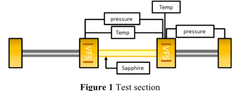
The test section (Figure 1) is composed of two adiabatic parts located at both ends of a transparent sapphire tube. Thermoplastic elements (in yellow in Figure 1) made of polyether ether ketone (PEEK) serve as an interconnection for these three sections and include two capacitance probes for the void fraction measurements. The two adiabatic parts are made of a stainless steel tube with an inner diameter of 6 mm whose lengths are of around 22 and 15 cm, respectively. To approach the adiabatic system, the tubes are covered with thermal insulation. The length of the first tube is adapted to its purpose of flow establishment before the sapphire tube. The second adiabatic section is long enough to enable the measurement of pressure drop along it. The section between the two stainless tubes is a 20 cm long sapphire tube with an inner diameter of 6 mm and a thickness of 1 mm. The outer surface is almost totally coated (except over a length of 1.5 cm at both tube ends) with ITO, an electrical conductive coating of 50 nanometers thick that enables a uniform heating of the outer surface. The measurements of voltage and current supplying the ITO coating allow measuring the heat flux applied on the sapphire tube. PT100 probes are located along the ITO deposit and on both sides of the tube to check the heating homogeneity. The ITO coating does not greatly affect the transparency of the sapphire tube; thus, the flow can be filmed during tests with a high-speed video camera, which enables the flow pattern identification.
Experiments are performed in normal gravity condition in vertical upward flow configuration and in microgravity conditions during parabolic trajectories in the Airbus Zero G aircraft. In the experiments the mass fluxes G range from 50 to 400 kg/m2/s, the wall heat flux q from 0.5 to 4 W/cm2. The
fluid can enter the test section in subcooled conditions with subcoolings up to -10°C or in saturated conditions with quality up to 0.5.
Figure 1 Test section VISUALISATION AND FLOW PATTERN
High-speed video pictures of the flow are taken through the transparent test section. Different flow pattern are observed (Figure 2) depending on the mass flux G, the wall heat flux q, the liquid subcooling at the test section entrance ∆T or the inlet quality.
Figure 2 Flow regime visualizations : bubbly flow on the left
sides and annular flow and the right sides in both microgravity and normal gravity conditions
For subcooled liquid entering the test section, the flow pattern observed is bubbly flow, with bubble nucleating on the heated wall, sliding along the wall and detaching. The effect of gravity is clearly visible on the pictures. The bubble size is larger in microgravity, due to larger bubble size at detachment from the wall and to enhanced effect of bubble coalescence. For
saturated conditions corresponding to higher quality x and higher heat flux, annular flow is observed with a liquid film flowing at the wall and a vapor core. The effect of gravity is less visible on the visualizations. Bubbly flow is observed for quality values smaller than 0.05 and annular flow occurs for qualities higher than 0.13. In between these 2 values, slug flow is mainly observed. It consists of long bubbles, which are separated by liquid slugs carrying smaller bubbles.
VOID FRACTION AND FILM THICKNESS
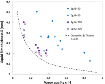
The void fraction a is measured by a capacitance probe consisting of 2 copper plates of 1 cm2 located on both sides of the tube. In annular flow, the liquid film thickness d is deduced from the void fraction by geometrical considerations 𝛿 = 𝐷 1 − 𝛼 /2, where D is the tube diameter. The effect of liquid droplet entrainment in the gas core proved to be negligible and is not considered in the calculation of the liquid film thickness [9]. In Figure 3, the film thickness is plotted versus the quality. The larger the mass flux G, the smaller the film thickness becomes. This is mainly due to the effect of the interfacial shear stress, which increases with the mass flux. The liquid film thickness is also smaller in microgravity than in vertical upward flow on ground, which could be explained by the effect of the hydrostatic pressure gradient acting on the liquid film in normal gravity. The film thickness values are larger than the one estimated with the void fraction correlation proposed by Cioncolini and Thome [18] for larger Reynolds numbers.
Figure 3 Liquid film thickness during microgravity and normal
gravity for two mass fluxes G = 50 kg/m2/s and G = 200
kg/m2/s
WALL AND INTERFACIAL FRICTION FACTORS
The wall shear stress tw is deduced from the pressure drop
measurements on the adiabatic section downstream the sapphire tube. In microgravity, it is directly proportional to the pressure drop and in normal gravity the hydrostatic pressure gradient has to be subtracted:
4𝜏+
𝐷 = −
𝑑𝑃
𝑑𝑧 − 𝜌0 1 − 𝛼 + 𝜌2𝛼 1 According to Lockhart and Martinelli [15], the frictional pressure gradient in two-phase flows can be expressed versus the single-phase liquid flow frictional pressure gradient
(dP/dz)L, and a multiplier 𝜙05: 4𝜏+ 𝐷 = 𝑑𝑃 𝑑𝑧 0𝜙0 5 with 𝜙 05= 1 + 𝐶 𝑋+ 1 𝑋5 and 𝑋 = 𝑑𝑃 𝑑𝑧 0 𝑑𝑃 𝑑𝑧 2 (2)
C=20 if the single-phase liquid and vapour flows are both
turbulent (tt) and C=12 if the single-phase liquid flow is laminar and single-phase vapour flows turbulent (lt). In Figure 4, the experimental value 𝜙0 is plotted versus Martinelli’s parameter X for G=50 and G=200 kg/m2/s. For G=200 kg/m2/s, the wall shear stress is the same in normal and microgravity conditions and close to Lockhart and Martinelli correlation for turbulent liquid and vapor flows. At G =50 kg/m2/s, the single
phase liquid flow is laminar and the single-phase liquid flow is turbulent. The wall shear stress is much higher in 1-g than in 0-g for G values smaller than 100 k0-g/m2/s.
Figure 4: Experimental two-phase multiplier according to
Martinelli parameter for 1-g (closed symbols) and 0-g (open symbols) conditions- comparisons with two correlations
proposed by Lockhart and Martinelli
In annular flow, the interfacial shear stress ti can be deduced
from simultaneous pressure drop and void fraction measurements by using the momentum balance equation for the vapor phase in adiabatic flow:
−𝛼𝑑𝑃
𝑑𝑧− 4𝜏A 𝛼
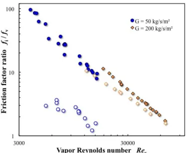
𝐷 − 𝜌2𝛼𝑔 = 0 3 The interfacial friction factor 𝑓A= 2𝜏A 𝜌2𝑈25 is found to
depend on both the liquid film thickness d and also the Reynolds number of the vapor core ReV=jV D/nV. The ratio fi/fV
is plotted versusReV in Figure 5, where fV=0.079 (ReV)-1/4. For
G=200 kg/m2/s, the interfacial friction factor in normal and
microgravity are close to each other. For G=50 kg/m2/s, the
interfacial shear stress is much lower in microgravity than in normal gravity.
Figure 5: Dimensionless interfacial friction factor versus vapor
Reynolds number in 1-g (closed symbols) and in 0-g (open symbols)
HEAT TRANSFER COEFFICIENT
The heat transfer coefficient is plotted in Figure 6 versus quality for two mass fluxes and a wall heat flux q=2W/cm2. At
G=200 kg/m2/s, the heat transfer coefficients are similar in 1-g
and in 0-g except at low qualities (x<0.15) in the subcooled boiling regime corresponding to bubbly and slug flows. At higher qualities, HTC does not depend on gravity and increases with quality. An annular flow regime is observed, the bubble nucleation in the liquid film disappears and the heat transfer is due to the evaporation of the liquid film. At lower mass flux
G=50 kg/m2/s, HTC is always lower in 0-g than in 1-g, even for quality larger than 0.15 corresponding to annular flow regimes.
The experimental results are compared to two correlations. The correlation of Kim and Mudawar [19] takes into account the contribution of nucleate boiling and convective boiling in the evaluation of the heat transfer coefficient. This correlation is in good agreement with experimental data at low mass flux in normal gravity where both nucleate and convective boiling play a significant role. It seems to overestimate the HTC at low quality probably because the nucleate boiling contribution is limited in our experiment due to the very smooth surface of the sapphire tube. For high quality and high mass flux, dominated by Two-phase Forced Convection, the experimental results are in better agreement with the model of Cioncolini and Thome [20] predicting the heat transfer coefficient for an evaporating turbulent liquid film. These trends are in agreement with previous results of Baltis et al. [17] and Ohta and Baba [4]. At low quality in the nucleate boiling regime, the HTC is lower in
microgravity than in normal gravity. As the quality and the mass flux increase, the effect of gravity on the HTC decreases.
Figure 6: Experimental heat transfer coefficients as a function
of quality for q=2W/cm2 in 1-g (closed symbols) and 0-g (open
symbols)– comparison with the correlations of Kim & Mudawar [19] and Cioncolini & Thome [20]
CONCLUSION
Experiments on flow boiling in a tube of 6 mm diameter are performed both in normal and microgravity conditions. Flow visualizations allow the determination of the flow regimes: bubbly, slug and annular flows. The void fraction is measured by capacitances probes. The liquid film thickness deduced from the void fraction measurements in annular flow regime decreases with the mass flux and is lower in microgravity conditions than on ground. The wall shear stress is well predicted by Lockhart and Martinelli correlation except at low mass fluxes (G < 100 kg/m2/s). The interfacial shear stress is typically smaller in microgravity conditions especially at low mass flux. Heat transfer coefficient measurements show that in nucleate boiling regime at low qualities, the values are smaller than the prediction of classical correlations, and smaller in microgravity than on ground. In convective boiling regime at high qualities, The results are in good agreement with the correlation of Cioncolini and Thome [20]. New experiments will be performed in collaboration with University of Maryland to access to the local instantaneous measurements of the heat transfer coefficient by using Infrared Thermography [21].
REFERENCES
[1] Colin C., Fabre J., Mc Quillen J., Bubble and slug flow at microgravity conditions : state of knowledge and open questions,
Chem. Engng. Com., Vol. 141-142, 1996, pp. 155-173
.
[2] Ohta, H., Microgravity heat transfer in flow boiling, Advances in
heat transfer, Vol 37, 2003, pp.1-76.
[3] Celata, G.P., Zummo, G., Flow Boiling Heat Transfer in Microgravity: Recent Progress, Multiphase Science and
[4] Ohta H. Baba S., Boiling experiments under microgravity conditions, Experimental Heat Transfer : A journal of Thermal
Energy Generation, Transport Storage and Conversion, Vol.
26 :2-3, 2013, pp. 266-295.
[5] Narcy M., Colin C., Two-phase pipe flow in microgravity without and with phase change: Recent progress and future prospects,
Interfacial Phenomena and Heat transfer, Vol. 3, 2015, pp. 1-17.
[6] Konishi C., Mudawar I., Review of flow boiling and critical heat flux in microgravity, Int. J. of Heat and Mass Transfer, Vol. 80, 2015, pp 469–493.
[7] Dukler, A. E., Fabre, J. A., McQuillen, J. B., and Vernon, R., Gas-liquid flow at microgravity conditions: Flow patterns and theirtransitions, Int. J. Multiphase Flow, Vol. 14, 1988, pp. 389– 400.
[8] Zhao, L. and Rezkallah, K. S., Gas liquid flow patterns at microgravity conditions, Int. J. Multiphase Flow, Vol. 19, 1993, pp. 751–763.
[9] Narcy, M., De Malmazet, E., and Colin, C., Flow boiling in tube under normal gravity and microgravity conditions, Int. J.
Multiphase Flow, Vol. 60, 2014, pp. 50–63, 2014.
[10] Zhao, J. F., Influence of bubble initial size on bubble-to-slug transition, J. Eng. Thermophys., vol. 26, pp. 793–795, 2005. [11] Zhao, J. F. and Hu, W. R., Slug to annular flow transition of
microgravity two-phase flow, Int. J. Multiphase Flow, Vol. 26, 2000, pp. 1295–1304.
[12] Elkow, K. J. and Rezkallah, K. S., Void fraction measurements in gas-liquid flows under 1-g and 0-g conditions using capacitance sensors, Int. J. Multiphase Flow, Vol. 23, 1997, pp. 815–829. [13] Zhao, L. and Rezkallah, K. S., Pressure drop in gas-liquid flow
patterns at microgravity conditions, Int. J. Multiphase Flow, Vol. 21, 1995, pp. 837–849.
[14] Chen, I. Y., Downing, R. S., Keshock, E., and Al-Sharif, M., Measurements and correlation of two-phase pressure drop under microgravity conditions, J. Thermophys., Vol. 5, 1991, pp. 514– 523.
[15] Lockhart, R. and Martinelli, R., Proposed correlation of data for isothermal two-phase two-component flow in pipes, Chemical
Eng. Progress, Vol. 45, 1949, pp. 39–48.
[16] Fang, X., Zhang, H., Xu, Y., and Su, X., Evaluation of using two-phase frictional pressure drop correlations for normal gravity to microgravity and reduced gravity, Adv. Space Res., Vol. 49, 2012, pp. 351–364.
[17] Baltis, C., Celata, G.P., Cumo, M., Saraceno, L., Zummo, G., Gravity Influence on Heat Transfer Rate in Flow Boiling,
Microgravity Sci. Technol., Vol. 24, 2012, pp. 203–213.
[18]Cioncolini, A., Thome, J.R., Void fraction prediction in annular two-phase flow, Int. J. Multiphase Flow, Vol 43, 2012, 72-84. [19] Kim S.M., Mudawar, I., Universal approach to predicting
saturated flow boiling heat transfer in mini/micro-channels – Part II. Two-phase heat transfer coefficient, International Journal of
Heat and Mass Transfer, Vol 64, 2013, pp 1239-1256.
[20] Cioncolini, A., Thome, J.R., Algebraic turbulence modeling in adiabatic and evaporation annular two-phase flow, Int. J. Heat
Fluid Flow, Vol 32, 2011, pp. 805–817.
[21] Kim, T.H., Kommer, E., Dessiatoun, S., Kim, J., Measurement of two-phase flow and heat transfer parameters using infrared thermometry., Int. J. Multiphase Flow, Vol. 40, 2012, 56–67.