SURFACE ENGINEERING FOR PARTS MADE BY
ADDITIVE MANUFACTURING
CONFERENCE PAPER · OCTOBER 2015 READS47
11 AUTHORS, INCLUDING: P. Rochus University of Liège 118 PUBLICATIONS 3,235 CITATIONS SEE PROFILE Jean Crahay CRM Group 15 PUBLICATIONS 13 CITATIONS SEE PROFILE Maïwenn Larnicol CRM Group 14 PUBLICATIONS 28 CITATIONS SEE PROFILE Laurent Pambaguian European Space Agency 29 PUBLICATIONS 168 CITATIONS SEE PROFILE__________________________________________ 1
Ulg, Belgium, [email protected] 2
Walopt, Belgium, [email protected] 3
CRM Group, Belgium, [email protected] 4
Thales Alenia Space France, France, [email protected] 5
CRM Group, Belgium, [email protected] 6
Sirris, Belgium, [email protected] 7
Thales Alenia Space France, France, [email protected]
SURFACE ENGINEERING FOR PARTS MADE BY ADDITIVE MANUFACTURING Nutal Nicolas
CRM Group, Belgium, [email protected]
Rochus P.1, Collette J.P.2, Crahay J.3, Jochem H.4, Larnicol M.5, Magnien J.6, Masse C.7, Rigo O.8, Vanhumbeeck J.F. 9 and Pambaguian L. 10
In the frame of ESA’s General Support Technology Programme (GSTP 6 E.1 Clean Space Initiative), focus is set on the surface preparation of metal parts made by additive manufacturing (AM). AM is a technology of choice for manufacturing of parts with complex shapes (heat exchangers, RF supports, optical parts…) and integrated functions such as conformal cooling channels, clips, hinges, etc. This opens the door for lightweight parts which are of prime importance for space applications. The potential of the AM technologies is however impeded by the quite rough surface finish that is observed on the as-manufactured parts. It is known that such a finish is likely to impact the performance of the parts. Several post-treatment techniques can be applied to improve the surface condition of the AM parts. However, so far, the influence of the successive post-processing steps on the final properties is not well established. Therefore, a better understanding of the impact of surface characteristics on the material behaviour is needed to expand the use of AM for high performance parts.
The objective of this study, supported by ESA, is to propose and evaluate various surface finishing techniques for parts made by the AM technologies, in order to check their compatibility, evaluate their properties and derive guidelines for future applications. CRM is the prime proposer of this study and is in charge of the surface treatment and characterisations. Sirris additive manufacturing facilities are used to produce the parts. Thales Alenia Space and Walopt are included into the industrial team to provide concrete application cases. The study focuses on metals. Two metals under study are presented here: AlSi10Mg and Ti6Al4V.
This paper is devoted to the early results of the first steps of surface preparation, namely material removal from the surface of the produced parts in order to improve their surface properties. As a first phase, tribo-finishing (TF) is tested on prototype parts to check its capabilities. Surface and volume parameters are analyzed, namely achieved roughness, material removal rate, location of removed material. The limitations in terms of geometry and applicability are discussed as well. These first observations should serve as guidelines for further application of AM for the design of parts used in space industry.
I. INTRODUCTION
Through the Clean Space Initiative [1], ESA showed its interest on manufacturing techniques having low environmental impact. Within this framework, AM offers significant reduction of waste material compared to
classical subtractive manufacturing. Besides, the
flexibility of the AM process allows the introduction of more efficient manufacturing practices, by reducing the production and inspection steps and thus simplifying the production chain. Finally, the dramatic decrease in the amount of raw materials combined with the design optimisation and possible reduction of life-cycle steps,
enables energy consumption decreasing and CO2 footprint reduction.
Nowadays, AM technologies applied on metals are able to produce functional, complex and optimized parts, which make them attractive for the aerospace sector. The achievable geometrical complexity allows developing more efficient parts (lighter, with internal cavities or channels…). These parts can find applications in thermal, structural or even optical functions. Today, the most relevant metallic materials for AM application are titanium (Ti6Al4V) and aluminium alloys (A357, A356) [2].
Recently, some papers [3] focused on the applications of AM technologies to different case studies in order to evaluate on real cases how these new techniques shall be implemented and what would be their impact on the way we are designing and manufacturing for space.
A key issue of AM is the high surface roughness, up to 20 microns Ra, and limited size accuracy of the produced parts. These issues could be overcome by a combination of, on the one hand, optimization of raw material, AM facilities and processing parameters, and, on the other hand, by an appropriate selection of post-treatment steps for surface improvement, for instance abrasion, etching or deposition processes.
This paper is dedicated to this last topic and more especially on the tribo-finishing (TF) of AlSi10Mg and Ti6Al4V parts.
II. ADDITIVE MANUFACTURING BASICS
The AM of metallic materials is performed using different methods. The most known are the Laser Beam Melting (LBM) and Electron Beam Melting (EBM), both members of the “Powder Bed Fusion” class [4]. Their basic principle is to spread a thin layer of metallic powder and to melt it locally respectively with laser or electron beam.
AM shows very attractive qualities:
• Decrease of the parts weight through optimized
design. This “topological optimization”, performed with special software, like Samcef, solid-thinking or 3-matics, leads to quite “organic” geometries that are therefore not achievable using traditional machining;
• Thanks to layer-by-layer manufacturing, geometry
complexity is no more a real obstacle and lattices, mesostructures or hollow parts can be produced;
• The time to market may be reduced up to 75%
depending on the usual technique used [5];
• Product improvement through design iteration
becomes possible. For instance, some components of the Mars Rover test vehicles [6] are the result of 70 parts/trials made by additive manufacturing;
• Lockheed Martin’s demonstrated production wastes
reduction down to 10-30% thanks to AM [7];
• Part simplification can be achieved at low cost and the assembly effort can be reduced. GE made fuel nozzle simplification from an assembly of 20 parts to only one [8];
• Last but not least, parts can be produced where they are needed. NASA, with the company "made in space", has installed a first AM device in the ISS [9] and architects Fosters and Partners designed buildings to be made by AM on the Moon [10]. These advantages are tempered by some bottlenecks that hold back decision makers in aerospace field:
• The lack of case studies to validate the technologies;
• The “poor” accuracy and repeatability of the
processes which often need post-machining;
• The limited size of the machine (600x400x500mm), as well as the short list of available materials;
• The “new but unknown” aspect of these technologies
compare to the well-known and experienced conventional machining;
• The important surface roughness driven by the
process itself, nature and grain size of the powder. This last point requires some clarifications as it is the subject of this paper. First, SLM devices use powder with grain size lower than 30 microns while EBM use powder up to 50 microns size. Therefore, layer thickness of the SLM process may be lower than EBM process. As a consequence, the manufactured surface quality, even limited, is usually better for SLM process than for EBM.
The geometry of the part influences the obtained roughness as well. For instance, the stair effect [11,12] is the most influent parameter until about 50° from the horizontal. Above 50°, other features affect the roughness more than the stair effect. One of them is the balling effect in which the meltpool breaks up on its sides (due to Marangoni convection that generates non uniform surface tension) into some leaks which solidify and alter the straight profile of the wished track [13].
III. SURFACE REQUIREMENTS
Before introducing the results, it is important to remind the surface requirements that are to be met for a potential application of AM to parts used in space industry. Those requirements are described here below and will allow the assessment of the TF results:
• Particular contamination: contamination by particles can be extremely harmful (degradation of optics, CCD, risk of short circuits…) and should be avoided by a thorough cleaning of the AM surfaces. It has to be noted that for both SLM and EBM loosely attached powder particles need to be removed, which is not necessarily easy due to the complexity of the
parts. In EBM, this is even more challenging due to the partial sintering of the powder induced by the high temperature / vacuum process;
• Low roughness: roughness is a cause for dust and dirts trapping and thus a cause of particulate contamination. Moreover, it can impede heat transfer between two surfaces in contact. Therefore high roughness must be avoided;
• Surface accuracy: narrow size tolerances applies on
some defined surfaces (fasteners, thermal
interfaces…) which can be difficult to meet in the case of AM;
• Surface cleanliness: the surface should be devoid of any contamination by fluids. Indeed, adsorbed fluids can lead to corrosion of the parts or outgassing. As a consequence, porosities of the AM surfaces should be reduced to avoid fluid entrapment;
• Compatibility with surface treatments: most of the surfaces need to be coated as a final step, for instance for achieving thermal properties or resistance to corrosion. The surface quality of the parts has a direct influence on the coating results. For instance, the anodizing layer mimics the surface characteristics of the underlying substrate. Besides, the growth mechanism of the layer, depending on the surface properties, has an impact on the final hardware dimensions.
All the above are often of no concern when using conventional machining where the surface quality to be obtained is part of the engineering drawing. In AM, the concept of surface quality needs to be refined and the above bullets are reflecting the functional requirements that surfaces indeed have.
IV. ADDITIVE MANUFACTURING PROCESS
PARAMETERS AND SAMPLES 250HL SLM machine from SLM Solutions was used to process aluminium (SLMA samples) and titanium (SLMT samples). EBMT titanium samples were processed using A2 EBM machine from ARCAM. Powder layer thickness was 30 microns for SLM and 50 microns for EBM. The laser power was 200W for aluminium and 350W for titanium. Concerning EBM, the maximum power was 4000W.
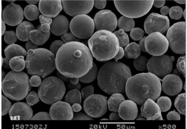
Titanium powders for SLM were acquired from TLS and from ARCAM for EBM. The aluminium powder was bought from SLM solutions. The microstructure of the EBM titanium powder is shown here below on the Fig. 1.
Fig. 1: Microstructure of the EBM titanium powder before processing.
This powder is spherical and within expected size range. The other powders show similar microstructures even if, as intended, the size distributions are different.
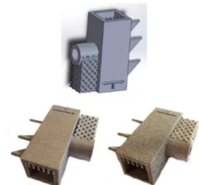
As depicted on the top of Fig. 2, the samples treated in this study were designed so as to integrate various types of structures that can be met in AM parts:
• Surfaces parallel/perpendicular to the support plate;
• Tilted surfaces (45°);
• Lattice, with different sizes;
• Heat ducts;
• Round surface;
• Hollow structure.
The sample dimensions are 35*15*30 mm.
The as-produced parts are illustrated on the bottom of Fig. 2. On the first sight, the samples produced by EBM are rougher than those produced by SLM.
Moreover, due to the process itself, EBMT samples have non-fully sintered powder, hard to remove, trapped inside the part. This will be an issue for potential applications.
Fig. 2: Proposed design (top), part produced in titanium by SLM (bottom left) and titanium by EBM (bottom right).
V. CHARACTERIZATION METHODS
2-D roughness measurements were performed using Mitutoyo SJ210 system. Ten measurements were realized each time on each area of interest. The roughness was measured in the vertical and horizontal direction regarding to the support plate as well as on a tilted area (45°) facing downward. The roughness is defined as the average of these three values.
The 3-D roughness profiles were taken using Veeco Wyko NT9100 confocal interferometer. Areas from 3*3mm up to 10*10mm were analysed.
3D scanner structured light ATOS 1 2Mpix from GOM was used to record the 3-D profiles. To enhance contrast, micron size TiO2 powder was added on the surface to enhance contrast during measurement. Hence the impact of these powders on the surface roughness can be neglected.
The samples underwent surface and cross-section observation using optical (Olympus AX70) and electron microscopes (JEOL 7001). For these analyses, the samples were set in a cold epoxy mounting resin and ground by silicon carbide pad down to 4000 grit. Then they were diamond polished down to 1 µm. After that, aluminium and titanium samples were etched respectively using Flick and Kroll etchant [14].
VI. SURFACE TREATMENT METHOD
Tribofinishing FBA 24 turbo system from Rösler, shown on the Fig. 3, was used to perform the surface treatment of the samples. This is a mechanical-chemical polishing process using “chips” to abrade the samples. Polymer RKB/W2 15P and ceramic RXX 10/15S chips were selected to treat, respectively, aluminium and titanium samples. During the process, the “chips” were automatically cleaned by a mix of a soap and water.
Fig. 3: Rösler FBA 24 turbo tribofinishing system. The treatments were performed at maximum frequency up to 60 minutes in the case of aluminium and up to 30 hours for titanium. After treatment, the parts were cleaned in an ultrasonic bath filled with ethanol to remove dust and cleaning water.
VII. INITIAL SAMPLE CHARACTERIZATION
As a first step, the surface of as-produced Al and Ti AM parts was characterised. Weight loss measurements were performed before and after ultrasonic cleaning to determine the amount of loose particles resulting from AM processing. Besides, the roughness of the samples was characterized after ultrasound cleaning. The results of these measurements are shown in Table 1.
SLMA SLMT EBMT Initial weight (g) 15.069 +/- 0.021 25.963 +/- 0.131 26.131 +/- 0.376 Weight loss (g) 0.015 +/- 0.001 0.054 +/- 0.004 0.018 +/- 0.003 Roughness Ra (µm) 10.6 +/-0.3 16.3 +/-0.4 19.4 +/-0.4 Pore volume fraction (%) 0.28 +/-0.10 0.22 +/-0.18 0.13 +/-0.09 Table 1: Characterizations of as-produced AM parts:
As can be seen, all parts undergo weight losses due to loose particles. These particles are incompletely melted during the AM process and are therefore weakly adhering to the part. Regarding SLM process, SLMA samples undergo smaller weight loss than SLMT samples. Taking into account the respective densities of the titanium and aluminium alloys, the loose particle volume of SLMT samples is twice that observed on the SLMA samples. For titanium processes, the observed weight loss in EBM is half the weight loss in SLM.
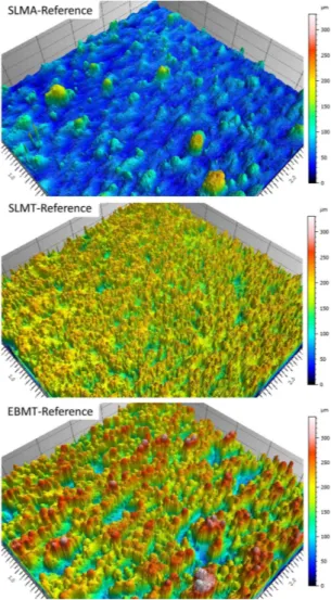
Roughness of the parts depends on the material and process too. EBMT parts are rougher than SLMT titanium parts. SLMA parts show the lowest roughness. These observations are confirmed by the interferometry measurements shown in Fig. 4.
Fig. 4: Interferometry measurement of vertical flat surfaces for the reference samples (3*3mm).
We can observe that the important roughness of the EBMT sample is due to “mushrooms” and deep valleys. The SLMA reference sample shows the smoother surface with some kind of hills. The surface roughness of the sample SLMT is due to small size round particles.
These observations are correlated with the powder size. This is confirmed by the SEM surface analysis of the samples shown on Fig. 5.
Fig. 5: SEM pictures showing the surface structure of the as-produced samples on the vertical flat surface.
The surface morphologies of the 3 samples are very different. These pictures confirm that the powder used for the SLMA samples is the smallest and that these powders are fully melted. Besides, it can be confirmed that the titanium powders used for the SLM are smaller than those used for the EBM. The microstructure of the SLMT reference sample indicates that the smallest titanium beads do not seem to be bonded tightly to the surface. On the contrary, it seems that there are no non-sticky powders on the SLMA samples. These observations allow explaining the weight loss differences observed above for the samples SLMT and SLMA.
Cross cuts were performed on the samples to determine the volume porosities. The microstructure of the SLMA sample is illustrated on Fig. 6.
Fig. 6: Light optical cross-section view of as-produced SLMA reference sample used to determine the volume porosity.
Porosities are seen in black and were measured using image analysis. These porosities are spread all over the surface. The half circles observed on the surface are the results of the local melting due to the laser. The average porosity observed on the reference samples, measured on 100 field of view, is reported in the Table 1. This table indicates that the samples produced by SLM have an average porosity around 0.22 up to 0.28%. Besides, the EBM allow reaching density up to 99.87%.
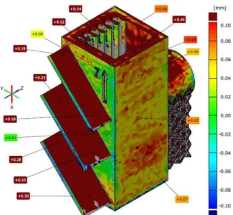
It is also interesting to compare the shape of the as-prepared AM part, measured by 3D profilometry, to the expected shape, as given by the CAO drawing. The result is presented on Fig. 7 for the SLMT sample.
Fig. 7: Comparison of the measured and CAO 3D profiles for the reference SLMT sample.
The grey areas indicate differences between the measured volume and CAO profile higher than 2mm.
Overthickness is observed on some areas on the samples:
• On the tilted surfaces (up to 0.3mm);
• On the lattice structure (up to 0.1mm);
• On some spots on the flat surface (up to 0.1mm);
• On the top of the part (up to 0.2mm)
Moreover, the holding supports needed to build the part, indicated by grey spots on the tilted surfaces, have to be removed.
Considering the surface requirements, all these observations confirm that surface processing is required.
VIII.EFFECT OF TRIBOFINISHING ON AM
SURFACES
The samples were processed with the TF system and cleaned. Then, their weight was measured just after TF to determine the amount of removed matter. The weight loss for the samples SLMA, SLMT and EBMT versus processing time is shown on the top of Fig. 8.
Fig. 8: Weight loss (top) and roughness (bottom) vs. treatment duration for the SLMA, SLMT and EBMT samples. The treatment duration for the SLMA samples is in min and in hour for the SLMT and EBMT samples.
It can be observed that the weight loss of the samples follows a logarithmic law. For the samples produced by EBM, it is not continuous, for the long duration treatments, due to the removal of the non-fully sintered powder. Besides, it can be observed that the titanium weight loss is more important for the samples produced by SLM rather than EBM, which is quite surprising as the original roughness of the EBM samples is higher than those produced by SLM. In fact, this is due to the microstructure shown on the Fig. 5. Indeed, contrary to the EBMT particles, the SLMT melted particles, seem to be loosely stuck to the surface. Therefore, their removal is easier and the weight loss is more important.
These measurements can be put in perspective with the evolution of average roughness of the parts, as shown on the bottom of Fig. 8. As expected, the average roughness of the samples decreases as the processing time increases, the decrease being more important at the beginning of the process. The average roughness of the samples SLMA decreases from 10.72 down to 4.43 after one hour of processing. The same behaviour is observed for the samples SLMT and EBMT. In that case, the roughness goes down to 5.42 (EBMT) and 3.33 (SLMT). It has to be observed that the original roughness difference for the samples EBMT and SLMT remains almost constant with time, except for the longest duration treatment when the roughness decrease starts to saturate. Finally, it should be pointed out that material removal becomes harder, i.e. it takes more time, as the part get smoother.
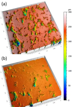
These observations are confirmed by the 3D roughness profiles. The profiles of the EBMT samples treated during 2 and 30 hours are illustrated hereafter on Fig. 9.
Fig. 9: Interferometry measurement of vertical flat surface for EBMT samples treated (a) 2 hours and (b) 30 hours.
These two pictures show the levelling effect of the TF system. Indeed, the numerous valleys observed on the sample after 2 hours almost disappear after 30 hours of treatment owing to the progressive erosion of the sample surface.
Those results are achieved for flat surfaces oriented vertically. However, as the TF process is anisotropic due to the circular motion of the abrading chips, it is interesting to compare the horizontal surfaces facing the chips (downward) or not (upward). The 3D profiles are shown on Fig. 10 for the EBMT sample treated for 30 hours.
Fig. 10: 3D roughness diagrams for horizontal faces of EBMT samples treated for 30 hours and facing (a) upward and (b) downward.
The anisotropic effect of the TF system is clearly shown on Fig. 10. Indeed, as compared to the vertical surface shown on Fig. 9 (b), the horizontal surface facing upward (Fig. 10 (a)) is less abraded. On the contrary, the downward-facing horizontal surface, and thus facing chips motion, is almost free from valleys, which means that the peaks were almost completely removed. The same trends are observed on SLMT and SLMA samples.
SEM pictures of EBMT samples treated for 5 and 30 hours are presented on Fig. 11.
Fig. 11: Effect of the tribofinishing system on EBMT samples treated for 5 and 30 hours.
The levelling effect of the TF is demonstrated on those two pictures. It can be seen that some original powder remains within the porosities after 5 hours of treatment. Those powders are grinded after 30 hours processing. For the longest treatment duration, a rather dense structure is obtained.
IX. EFFECT OF TRIBOFINISHING ON VOLUME
After this detailed study on the effect of the TF system on the surface, it is interesting to study the effect of TF on the overall volume of the parts.
Photographs of the SLMA, SLMT and EBMT parts after TF processing for the longest duration are shown on Fig. 12.
Fig. 12: Effect of the tribofinishing system on the samples treated for 60 minutes (top, SLMA) and 30 hours (bottom left, EBMT and bottom right, SLMT). The surface of the parts offers a shiny aspect due to the roughness decrease. Besides, edges and corners are rounded. The lattice structure is damaged. The location of removed material was determined using the GOM system. This was obtained from the comparison of the 3D profile before and after TF. The results of the measurements for the sample SLMT treated for 30 hours is illustrated on the Fig. 13.
Fig. 13: Comparison of the measured and CAO 3D profiles for the SLMT sample treated for 30 hours.
The grey areas indicate differences between the measured volume and CAO profile higher than 2mm.
The results described in the previous section show that the TF system abrades surfaces and leads to roughness decrease. As can be seen in grey and blue on Fig. 13, this abrasion is more important on the edge of the parts. Besides, TF had almost no effect on heat ducts or tilted areas as the size of the chips used to abrade the structure are larger than the free space.
Nevertheless, it can be seen that the difference on the flat surfaces between the measured volume and the CAO profiles after processing is lower than before (see Fig. 7).
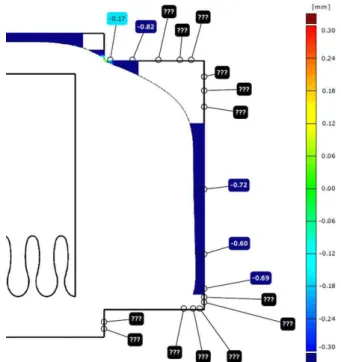
The material removal can reach a few mm for the thin tilted areas and edges of the parts, as shown on the following side-view.
Fig. 14: Side-view of the bottom of the sample SLMT treated for 30 hours.
In this case, the blue areas indicate material removal higher than 0.3mm. The highest measured difference between the part and the profile is 0.82mm. On the basis of the expected CAO profile, it can be estimated that the difference reach values higher than 3mm.
X. TRIBOFINISHING POTENTIALITIES From the previous observation and tests, different remarks can be drawn about TF potentialities and drawbacks regarding the surface requirements listed before.
No loose particles
The TF leads to loose particle removal due to the vibration and abrasion. However, particles entrapped in hollow or complex structures are not influenced by the TF as the chips are too large to access these areas. Small but non adherent particles are generated through the TF process. These particles are easily removed by ultrasound cleaning.
Surface roughness
Roughness down to 1 micron can be achieved on accessible surfaces, preferentially flat, or edges and corners. However, acute angles, lattice, hollow structures are not properly treated.
Shape accuracy
TF reduces roughness of flat surfaces with limited material removal. Unfortunately, this treatment rounds the edges and corners. This rounding could be taken into account with proper design considering homogeneous angle rounding thanks to parts rotation. Besides, the material removal could be integrated during the design of the part to reach the required sizes and dimensions after TF. Nevertheless, the limited accessibility of the TF confines the methods to parts with limited complexity. Surface cleanliness
Contrary to chemical polishing, TF is a process that is almost fully dry. Indeed, except “soap” and water used to clean the chips during the process, no liquid is involved. A proper cleaning after the process allows removing all the fluids.
Compatibility with surface treatments
The parts treated using TF are ready for further surface treatment as the thick oxide layer is removed during the TF. Besides, the achieved roughness on flat surfaces is suitable for coating.
To sum up, TF could be applied for parts produced by AM to be used in space industry if proper cautions are taken:
• Short radius angles, lattice structures, hollow bodies, limited space between surfaces should be avoided;
• Proper cleaning of the surface after treatment is performed;
• Design of the parts is modified taking into account the particularities of the TF listed above concerning material removal.
XI. CONCLUSIONS
This paper proposed an approach to the surface treatment of parts produced by AM using tribofinishing system. The effect of the TF on surface properties (roughness) and volume properties (location of material removal, material removal rate) were evaluated. Besides, the limitations in terms of geometry and applicability were discussed. These observations were performed on aluminium AlSi10Mg and on titanium Ti6Al4V alloys.
The preliminary observations led to the conclusion that tribofishing is well adapted to the surface treatment of quite large parts that are not too complex (no lattice, no hollow bodies or heat ducts). On the contrary, flat surfaces and high radius curvatures could be treated down to a few µm Ra. As this method do not use corrosive liquid for the treatment, no detrimental surface contamination is expected.
XII. ACKNOWLEDGMENTS
This work has been founded by the European Space
Agency ESA-ESTEC under contract number
4000113253/15/NL/SW. The authors wish to thank their colleagues who have made this work possible.
XIII.LIST OF ABREVIATIONS
AM EBM SLM TF SLMA SLMT EBMT Additive Manufacturing Electron Beam Melting Selective Laser Melting Tribo-Finishing
Selective Laser Melting of Aluminium Selective Laser Melting of Titanium Electron Beam Melting of Titanium
XIV.REFERENCES
1. Barbier, X. Compendium of Potential Activities for 2013 & 2014 GSTP-6 Element 1 (ref TEC-SGT/2013-006/XB). (2013).
2. Campbell, F. J. Manufacturing Technology for Aerospace Structural Materials, 1st Edition.
3. Rochus, P. et al. New applications of Advanced Manufacturing Methods for space instrumentation and Systems of Nanospacecraft. in IAC 2014 (2014).
4. Standard Terminology for Additive
Manufacturing Technologies. (ASTM International, 2012).
5. Coykendall, J. et al. 3D opportunity for
aerospace and defence. (2014). at
<http://dupress.com/articles/additive-manufacturing-3d-opportunity-in-aerospace/>
6. Crandall, R. Where Will Additive Manufacturing
Take Us? APICS (2013). at
<http://www.apics.org/industry-content- research/publications/apics-magazine/apics-magazine--- landing-page---everyone/2013/01/28/where-will-additive-manufacturing-take-us->
7. Ryan R Dehoff, C. T. Case Study: Additive
Manufacturing of Aerospace Brackets. Advanced
Materials and Processes 171, (2013).
8. Additive Manufacturing: Aerospace’s Next
Disruptive Technology. at
<http://www.icfi.com/insights/presentations/aviation/201 4-additive-manufacturing-aerospaces-next-disruptive-technology>
9. Made In Space | Additive Manufacturing in
Space. at <http://www.madeinspace.us/>
10. Plans to 3D print Moon building. BBC News at <http://www.bbc.co.uk/news/technology-21293258>
11. Gao, W. et al. The status, challenges, and future of additive manufacturing in engineering. Computer-Aided Design doi:10.1016/j.cad.2015.04.001
12. Strano, G., Hao, L., Everson, R. M. & Evans, K. E. Surface roughness analysis, modelling and prediction in selective laser melting. Journal of Materials Processing Technology 213, 589–597 (2013).
13. Dongdong, G. Laser Additive Manufacturing of
High-Performance Materials. (Springer). at
<http://www.springer.com/us/book/9783662460887> 14. ASM Handbook Volume 9: Metallography and
Microstructures - ASM International. at