HAL Id: hal-01799722
https://hal-mines-albi.archives-ouvertes.fr/hal-01799722
Submitted on 10 Jul 2018
HAL is a multi-disciplinary open access
archive for the deposit and dissemination of
sci-entific research documents, whether they are
pub-lished or not. The documents may come from
teaching and research institutions in France or
abroad, or from public or private research centers.
L’archive ouverte pluridisciplinaire HAL, est
destinée au dépôt et à la diffusion de documents
scientifiques de niveau recherche, publiés ou non,
émanant des établissements d’enseignement et de
recherche français ou étrangers, des laboratoires
publics ou privés.
by Steam Thermolysis
Maxime Boulanghien, Mohamed R’Mili, Gérard Bernhart, Florentin Berthet,
Yannick Soudais
To cite this version:
Maxime Boulanghien, Mohamed R’Mili, Gérard Bernhart, Florentin Berthet, Yannick Soudais.
Me-chanical Characterization of Carbon Fibres Recycled by Steam Thermolysis: A Statistical Approach.
Advances in Materials Science and Engineering, Hindawi Publishing Corporation, 2018, 2018, art.
8630232-10 p. �10.1155/2018/8630232�. �hal-01799722�
Research Article
Mechanical Characterization of Carbon Fibres Recycled by Steam
Thermolysis: A Statistical Approach
M. Boulanghien ,
1,2,3M. R’Mili,
4G. Bernhart,
1F. Berthet,
1and Y. Soudais
21Institut Cl´ement Ader (ICA), Universit´e de Toulouse, CNRS, Mines Albi, UPS, INSA, ISAE-SUPAERO, Campus Jarlard,
81013 Albi CT Cedex 09, France
2Universit´e de Toulouse, Mines Albi, UMR CNRS 5302, Centre RAPSODEE, Campus Jarlard, F-81013 Albi cedex 09, France 3Alpha Recyclage Composites, 4 rue Jules V´edrines, 31400 Toulouse, France
4INSA-Lyon, MATEIS, UMR CNRS 5510, Universit´e de Lyon, 7 Avenue Jean Capelle, 69621 Villeurbanne, France Correspondence should be addressed to M. Boulanghien; mboulang@mines-albi.fr
Received 16 March 2018; Accepted 23 April 2018; Published 20 May 2018 Academic Editor: Akihiko Kimura
Copyright © 2018 M. Boulanghien et al. This is an open access article distributed under the Creative Commons Attribution License, which permits unrestricted use, distribution, and reproduction in any medium, provided the original work is properly cited.
The recent development of technologies for recycling carbon fibre reinforced plastics (CFRPs) leads to the need to evaluate the mechanical response of recycled carbon fibres. As these fibres are likely to be degraded during the recycling treatment, it is very important to determine their tensile residual properties so as to evaluate their ability as reinforcement for new composite materials. Carbon fibres reclaimed by a steam-thermal treatment applied to degrade the epoxy resin matrix of a CFRP are here analysed. Two conditions were chosen so as to reach two degradation efficiency levels of the steam thermolysis. Several carbon fibre samples were selected for mechanical testing carried out either on single filaments using single fibre tensile tests or on fibre tows using bundle tensile tests. It is shown that the single fibre tensile test leads to a wide variability of statistical parameters derived from the analysis. Bundle tensile tests results were able to indicate that fibre strength of recycled carbon fibre is similar to corresponding as-received carbon fibres thanks to a statistically relevant database. Wide number of tested filaments enabled indeed to obtain low scatters.
1. Introduction
Carbon fibre reinforced plastics (CFRPs) have been widely used these last years in many industrial, sportive, and transport applications, especially for their low weight and high strength. The global carbon fibre market is expected to reach high annual growth rates until the next few years. Although the current global demand for carbon fibre, 82,400 tons per year, is lower than expected in last year’s market reports [1, 2], it is still expected to grow at a minimal annual rate of 9.0%. Global demand in carbon fibres is expected to reach 116,000 tons per year in 2021 for the less optimistic scenario [3] whereas other projections estimate a 150,200 tons demand [4, 5]. In addition, the carbon fibre reinforced composites market obviously shows very similar growth trends. While in 2013 the global demand for this kind of
material was 72,000 tons, recent reports expect this market to reach a 191,000 tons demand by 2022 [6]. The high growth perspectives of wind turbines and aerospace industries can mainly explain the intensification in using CFRP as their recent introduction in the automotive industry. This dra-matic increase in using carbon fibre means that the quantity of generated waste will also rise significantly, either as an off-cut or as an end-of-life composite product. Thus, it appears to be critical to develop suitable composite recycling tech-nologies that could offer interesting environmental and economic perspectives. If the environmental and social responsibilities are the first arguments for such development efforts, market economics is still a key factor. Considering that the carbon fibre market’s potential is clearly affected by the high price of carbon fibre, although its production ca-pacity is nowadays growing, there is a huge opportunity for Volume 2018, Article ID 8630232, 10 pages
future or existing recycled carbon fibre producers and processers to answer new needs.
Although landfilling is currently the main option to manage CFRP wastes, the high added value of carbon fibre associated with a restrictive European legislation [7, 8] has driven researchers and engineers to look for new recycling technologies, especially as life cycle analysis already showed that the environmental benefit is much higher for a recycling scenario than for a classical incineration or landfilling [9–11]. These last years, the main studied approach has been to degrade the organic matrix to leave clean the carbon fibres, these ones being valorised as reinforcement in second-generation composite products. Various technologies fo-cused much effort in this way: solvolysis [12], pyrolysis [13], and steam thermolysis [14].
Solvolysis is a chemical process based on the organic matrix depolymerisation by means of a solvent. Most of the time, near- or supercritical conditions are required to obtain the best results and avoid the use of aggressive chemical solvents that make the treatment more complex. Methanol [15], propanol [16–18], water [19, 20], or even a mixture of water and ethanol [21] in supercritical conditions were successfully used: the removal of an epoxy matrix can reach 100% without loss of tensile strength of reclaimed carbon fibres. Although more investigation efforts have been made in these methods, there is still no example of an industrial scale launch of this technology applied to the CFRP recy-cling: supercritical reactors are expensive as they have to be designed for high temperatures, high pressure, and a cor-rosive environment.
Pyrolysis is based on the organic matrix thermal deg-radation. It has been the most studied thermal process [22–24], and some variations can be found as the microwave heating pyrolysis [25, 26]. Depending on the matrix nature, and the considered variation, the efficiency of such a treat-ment is variable: from 80% to 99% of eliminated resin. Reclaimed carbon fibre tensile strength can be degraded due to the presence of char on the fibre surface that needs to be eliminated by an air posttreatment. However, in spite of lower results than what can be obtained in solvolysis, py-rolysis is a cost-efficient technology well suited to the rel-atively undeveloped composites recycling market. These research efforts have even been commercially applied by European companies such as ELG Carbon Fibre (United Kingdom), Karborek (Italia), Reciclalia (Spain), or CFK Valley Stade Recycling (Germany) and American ones such as Adherent Technologies Inc or Carbon Conversions.
Finally, steam thermolysis is a thermochemical process using superheated steam at environmental pressure for degrading organic materials. It is a cost-efficient technology as no energy-consuming posttreatment of reclaimed fibres is needed, nor high pressure environment requiring discon-tinuous working flow and expensive reactors. It has been applied to the material recovery of circuit boards [27], to the degradation of polyimide [28], or to the production of oil from biomass [29]. Only few studies focused on the steam-thermolysis process applied to the recovery of carbon fibre from CFRP wastes [10, 30–33]. Steam thermolysis enables to efficiently degrade the organic matrix of the CFRP waste,
which makes this technology a serious alternative. The aim here is to evaluate the efficiency of this technology by proposing a true mechanical characterization of the reclaimed carbon fibres considering two techniques: single fibre tensile test (SFTT) and bundle tensile test (BTT). Using the widely used SFTT technique, some inherent variability sources of the tensile strength determination can appear as the specimen selection, the damage of the fibres during the sampling operation, and the difficulty in getting a perfect alignment of the fibre with the tensile machine. Hence, the bundle tensile test can become an alternative for the tensile strength determination of recycled carbon fibres, as it has been successfully used to study virgin glass, ceramic, and carbon fibres.
2. Theoretical Background
2.1. Bundle Model. The theoretical model of dry bundle of
fibres considers a discrete set of N parallel fibres with sta-tistically distributed strength. When the bundle is loaded, fibres’ mechanical behaviour is linear elastic until their
failure at the applied stress σi, i � 1, . . . , N. When a fibre
breaks in the bundle, the supplementary load that was carried by the broken fibre is equally distributed. Two distribution cases can be differentiated. The global load sharing (GLS) considers that the supplementary load is equally distributed among the survival fibres whereas the local load sharing (LLS) considers that the supplementary load is equally distributed among the neighbouring fibres. The first case is here considered but needs to fit assumptions, called Coleman’s conditions: fibre length must be constant within the bundle, stress-strain relationship follows Hooke’s law until failure, the released load at a fibre break is uni-formly distributed among the surviving fibres, and no ex-ternal phenomena should lead to a premature fracture of fibres. As a consequence, any friction phenomena between fibres within the bundle must be avoided as it would lead to a catastrophic fracture of the whole bundle. Specific cares are taken to avoid this effect.
2.2. Statistical Distribution of Fibre Strength. Fracture of
carbon fibres is likely to be caused by flaws within the gauge length. Flaws are randomly distributed and show a high heterogeneity in size, location, and severity. Then, a wide variation in failure load is expected and the ultimate tensile strengths measured on specimens have a statistical distribution. Weibull analysis is a well-known method typically used for fracture statistics for brittle materials. For a single gauge length and uniform uniaxial tensile stresses, the Weibull equation of failure probability is given by: P �1 − exp − V V0 ε ε0 m , (1)
where V is the stressed volume and V0a reference volume,
ε0�σ0/Ef, σ0being the scale factor, Efthe Young modulus
of a fibre, and m the Weibull modulus. As a common ap-proach, a Weibull diagram is usually constructed by using
empirical estimators of failure probability. Then, the sta-tistical parameters are obtained by fitting (1) to the Weibull plot.
However, the validity of the normal distribution to describe the distribution of strengths has already been shown [34] and the statistical parameters that were derived from are considered to provide a better fit to the data. Besides, it was demonstrated that the statistical parameters derived from a Weibull distribution showed a wide vari-ability due to the construction of Weibull plots using an estimator and the sample size generally too small that does not enable to take into account the natural variability of material properties. Therefore, a statistically relevant data-base and normal distribution are used for the analysis of failure data. Equations of probability density function f(ε)
and normal distribution PN(E≤ ε) are as follows:
f(ε) � 1 S√��2π�exp −(ε − μ)2 2S2 , PN(E≤ ε) � ε 0 f(ε) dε, (2)
with ε the strain, μ the mean of strain, and S its standard deviation.
2.3. Bundle Behaviour. Assuming that the applied load is
uniformly distributed among the surviving fibres in the tow and that fibres have a linear load-strain relationship up to breakage, the force-strain relation during a tensile test is given by [35]:
F(ε) � N0· Af· Ef·ε · [1 − P(ε)], (3)
where N0 is the number of initially loaded fibres, Af is the
cross-sectional area of each of the fibres, Ef is their Young’s
modulus, ε is the applied strain, and P(ε) is the probability of failure of a fibre at a strain ε, given by (2).
3. Materials and Methods
3.1. Composite Manufacturing. Composite samples were
made by liquid resin infusion. A low-viscosity bicomponent system was used: a Sicomin SR1710 Infusion epoxy resin mixed with a Sicomin SD8822 hardener. A twenty hours at
room temperature plus sixteen hours at 60°C polymerisation
cycle were applied before removing the system from the mould. Details of procedure can be found in a work of Balea et al. [36]. Carbon reinforcement was a carbon twill 2 × 2 (Hexcel 46285 U1200) made from AS4C carbon fibres. Sixteen 400 × 400 mm plies were stacked so as to obtain an approximately 800 grams plate, for a 4 mm final thickness. The average fibre mass fraction was 66% corresponding to a fibre volume fraction of 55.5%. These plates were cut by the mean of a circular saw in order to get 50 × 120 mm samples able to be used in the steam-thermolysis reactor.
3.2. Recycling Carbon Fibres. The recycling was conducted in
a bench-scale reactor as shown in Figure 1. Previous in-house
produced composite samples are treated by steam thermolysis so as to reclaim carbon fibres. The thermochemical process uses superheated steam at atmospheric pressure in order to degrade the organic matrix of the composite.
A removable crucible was made from a stainless-steel fabric (own design, 1000 mL). This crucible was coupled with a thermogravimetric analyser and placed within the heating zone. The experimental reactor is provided with an easy opening chamber located on the top of the apparatus. Once the experimental parameters reached the desired level, the chamber that contains scrap composites samples (100 g) is opened so as to let them fall into the reactor. After epoxy resin was decomposed, and once the system cooled down, recycled carbon fibres were collected from the reactor. No cleaning of the surface is required before their use. Three categories of products are actually collected: a solid fraction that is constituted of recycled carbon fibres, a permanent gaseous fraction principally constituted of methane and carbon monoxides, and a last condensable gaseous fraction that is constituted of pyridines, benzene, and phenols [31]. A unit made up of a steam generator and a nitrogen input manages atmosphere control. The experimental device is designed to operate in a wide range of conditions:
tem-perature from 100 to 1000°C, steam flow rate from 0 to
1000 g·h−1, and nitrogen flow rate from 0 to 20 L·min−1.
Experimental conditions and reclaimed samples are de-scribed in Table 1. Experiments were carried out under atmospheric pressure for two hours at two temperatures:
400°C and 500°C. In both cases, the nitrogen flow rate was set
to 10.8 L·min−1 whereas the steam flow rate was 90 g·h−1.
Reclaimed carbon fibres from these treatments are, re-spectively, named RF400 and RF500.
3.3. Fibre Morphology. Yields of eliminated resin were
measured by dissolution of remaining resin with hot sul-phuric acid according to the French standard NF EN 2564. Environmental scanning electron microscopy (ESEM) was used to observe surface texture and morphology of the fibres as well as visual signs of residual resin impurities. Fibre bundles of each sample were randomly selected and mounted on an adhesive carbon layer stuck onto an alu-minium stub. As carbon fibre is conductive, no other specific preparation was needed. The acceleration voltage was 20 kV. Diameters of the fibres were also measured using image analysis with ImageJ software. For each sample, an average diameter was determined by measuring a population of 200 fibres from an image database obtained during the corre-sponding ESEM analysis.
3.4. Mechanical Properties
3.4.1. Single Fibre Tensile Test. The most common technique,
the single fibre tensile test (SFTT), measures the strength of individual fibres. By measuring many fibres, a wide pop-ulation can be formed and used for stress analysis. This test was employed to determine the tensile strength of the three fibre types of the study. Method is based on international standards ISO 11566 [37]. A single filament is bonded to
a paper window with cyanoacrylate Loctite 409. Then, the specimen is inserted into a tensile rig equipped with a 5 N load cell. The carbon fibre has to be carefully aligned with the tensile testing machine axis. Each side of the paper window was cut before testing. The gauge length was 25 mm. The crosshead speed was set to 0.1 mm/min. Carbon fibre specimens were loaded at room temperature until failure, and the force displacement curve was recorded. At least 40 filaments were tested for each fibre type, that is, VF, RF400, and RF500.
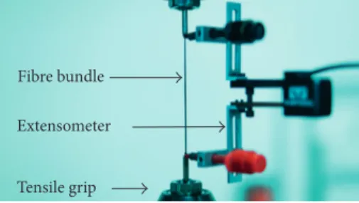
3.4.2. Bundle Tensile Test. Mechanical tests were also carried
out on fibre bundles using bundle tensile tests (BTTs) so as to quantify the tensile strength of the recycled carbon fibres. It is based on the random and individual fibre failure within the bundle. Therefore, statistics laws are used for analysis. This statistical data approach enables to take into consid-eration a wide single filament population.
One of the difficulties is the measurement of a reliable bundle strain. An extensometer is placed on heat shrink tubes previously threaded on each tip of the bundle, as it is shown in Figure 2, to define the gauge length. Each tip is impregnated with Araldite 2015 resin and then
poly-merised at 70°C for one hour. Impregnated tips are then
inserted in metallic tubes and filled again with Araldite
2015 resin and polymerised at 70°C for one hour. Metallic
tubes enable a regular clamping by tensile grips. During any of these preparation steps, a specific care must be taken to avoid any handling of the fibre bundle within the gauge length. Before loading, the sample is lubricated by petroleum wetting, avoiding premature rupture due to friction phenomena between fibres within the bundle. This meticulous experimental procedure is also described in [38, 39].
The tensile tests were performed using a pneumatic testing machine with a 2 kN cell. They were carried out at
Table1: Samples of the study and associated steam-thermolysis experimental conditions.
Samples Treatment temperature (°C) Nitrogen flow rate (L/min) Steam flow rate (g/h) Treatment time (h)
VF Virgin fibre (reference) — — —
RF400 400 10.8 90 2
RF500 500 10.8 90 2
Removable crucible
Thermogravimetric analyser Composite samples
Easy opening chamber Output Gas
Steam Nitrogen Heating zone
Temperature measurement
room temperature under constant displacement rate of 0.06 mm/min on specimens prepared according to the previous procedure with a gauge length of 60 mm. Carbon fibre bundles were loaded until failure, and the load dis-placement curve was recorded. For each fibre type, about 3000 filaments were tested in each tow. For RF500 fibre, 3 tows were tested so as to make sure measurements are repeatable.
3.4.3. Methods of Failure Data Analysis. For single fibre
analysis, the means of ultimate strengths are known by collecting individual data. Both normal and Weibull dis-tributions are used. Weibull plots are constructed using an
empirical distribution function Pj (j − 0.5)/N with N the
sample size and j the specimen number.
For bundle analysis, the mean of fibre tensile strength and its standard deviation are obtained by fitting an ana-lytical curve based on (4) to the experimental data. Firstly, the load-strain curve of the bundle is determined by the tensile test as described in 3.4.2. Then, the initial slope of the linear part of the analytical curve is fitted to the experimental one. Equation (3) can also be written as:
F(ε) N0· Af· Ef· ε · [1 − P(ε)] R0ε · [1 − P(ε)], (4)
where R0is the initial slope of the (F− ε) curve. Finally, by
fitting the nonlinear parts of experimental and analytical curves, the mean of strains to failure μ and its standard deviation S are determined. Assuming Young’s modulus of each type of fibre is constant, the mean of ultimate tensile strength of each type of fibre and its standard deviation can be determined.
4. Results
4.1. Efficiency of Steam-Thermal Treatments. The
tempera-ture is an important parameter on the degradation kinetic and thus on the efficiency of the treatment. Measurements of
yields of eliminated resin are shown in Table 2. A 400°C
thermolysis did not enable the elimination of all the resin of the composite (yield of eliminated resin reached 95% in
mass) whereas the 500°C treatment was more effective and
enabled to degrade all the epoxy resin (yield of eliminated resin is higher than 99% in mass).
Figure 3 shows an ESEM image of the virgin fibre VF and recycled carbon fibre RF500. Examination of images of several fibres from different batches clearly showed no visible alteration of the surface topography due to steam
thermolysis. Similar regular and clean surfaces are observed, indicating the efficiency of the treatment that removed the most part of the resin of the composite material. Recycled RF400 fibres are shown in Figure 4. A few small particles can be seen and are attributed to resin residues that stuck on the
surface. The 400°C steam-thermal treatment left little
quantities of residual resin on a smooth and regular surface (5% by mass of residual resin). The particles have a size ranging from 2 to 20 micrometres, avoiding individual fibres to be properly separated. These observations obviously show the importance of temperature on the degradation kinetic. The mean diameters were calculated as 7.1, 6.9, and 6.9 μm, respectively, for VF, RF400, and RF500 fibres (Table 1). This is in good agreement with the value of 6.9 μm provided by the manufacturer [40]. It may be inferred from the similarity of the mean and standard deviation values of the fibres, with visual evidence from the ESEM, that there was no alternation to the fibre morphology.
4.2. Mechanical Properties
4.2.1. Single Fibre Mechanical Analysis. Two statistical
pa-rameters are deduced from the analysis: the mean of strength
μ and its standard deviation S. From the experimental data,
the 95% confidence interval of mean value is also established as it is often used as an indicator of the precision of an estimate derived from an analysis. For a sample size N 40,
μ the sample mean, and S the standard deviation, the 95%
confidence interval of mean value (Ic) is given by:
Ic μ − 2.02 S
N
√ ; μ + 2.02√S N
. (5)
Statistical parameters of normal distribution of strength deduced from SFTT are reported in Table 3. The average tensile strength of RF500 fibre is slightly different from that of the corresponding virgin fibre VF. A 4% decrease was observed. However, the result shows a high degree of var-iability with a standard deviation of about 540 MPa for a tensile strength of 3610 MPa. Looking at the frame given by these 95% confidence intervals, it appears to be difficult to obtain reliable results. Indeed, there is no statistically rep-resentative difference between the two samples. Thus, it could be premature to affirm that the tensile strength loss is really significant or not, although it could be negligible regarding the low decrease of only 4%. Nevertheless, it can be stated that reclaimed RF400 fibre showed substantial strength degradation relatively to the virgin fibre. Even taking into account the high degree of variability of mea-surements, tensile strength loss of RF400 fibre is likely to be
Table 2: Studied samples and associated steam-thermolysis ex-perimental conditions.
Fibres Yield of eliminatedresin (%) Mean diameter (standarddeviation) (μm)
VF — 7.1 (0.7) RF400 95 6.9 (0.7) RF500 >99 6.9 (0.7) Fibre bundle Extensometer Tensile grip
significant. This could be explained by the presence of re-sidual resin on the fibre surface that could act as stress concentrators leading to a premature failure of the fibre. Figure 5 shows mean stress-displacement curves obtained from single fibre testing and confidence interval on the mean value of tensile strength and displacement at failure. As it can be seen that average value of failure strain is lower than that of virgin and RF500 fibres, it confirms that the single fibre fails before reaching its maximum stress level.
Weibull diagrams derived from this analysis are also presented in Figure 6, as they are a usual approach for describing failure behaviour of brittle materials. They are compared to log-log graphs of normal distributions of stress to failure for each sample. A good agreement between both distributions is obtained for RF400 fibre. However, a clear discrepancy can be noticed at the low failure probabilities for VF and RF500 fibres. The RF500 Weibull plot suggests the presence of two domains reflecting two distinct failure modes for this fibre whereas it does not seem to be the case in Figure 7 showing the probability density function of this fibre and the associated experimental points. Indeed, at the
lower stress values, experimental data do not clearly show two distinct populations. Many other reasons can be ad-vanced to explain discrepancies on Weibull plots and high scatters observed on SFTT results: the use of an empirical estimator, the selection and damage of the fibres during the operation of sampling, or the low sample size leading to a low representativity in the case of brittle materials [35, 41]. A wide distribution in flaw size is inevitable considering the selection of test specimens. While variability cannot be avoided until a relevant database is used for failure analysis,
Table 3: Statistical parameters of normal distributions obtained from single fibre tensile tests analysis and related 95% confidence intervals.
Fibre
samples Mean of tensilestrength (MPa)
Standard deviation (MPa) 95% confidence interval (MPa) VF 3776 547 146 RF400 3272 672 179 RF500 3610 540 144 4000 3000 2000 1000 0 Ap plied str ess (MP a) 0.0 0.1 0.2 0.3 0.4 0.5 0.6 0.7 0.8 Displacement (mm) VF RF400 RF500
Figure5: Mean displacement-applied stress curves obtained from SFFT and 95% confidence intervals.
(a) (b)
Figure3: ESEM images of VF (a) and RF500 (b) fibres (×5000).
(a) (b)
there is no means to evaluate the validity of this selection and so to validate the full strength retention of recycled carbon fibres.
4.2.2. Bundle Mechanical Analysis. Figure 8 shows typical
load-strain curves obtained from bundle mechanical anal-ysis. It is easy to see that a good agreement is obtained between experiment and model: experimental curve and normal distribution-based curve were well fitted. The load decrease beyond maximum fits well with that obtained experimentally. Maximum load also depends on the number of filaments in each tested tow and is consequently not always the same for a same sample. Exact number of fila-ments is determined from the initial slope of the load-strain
curve. Statistical parameters of normal distribution of strength extracted from analysis of bundle tensile tests are listed in Table 4.
The RF400 sample shows the lowest mean strength of 3657 MPa whereas the VF sample and RF500 sample show a quite similar mean strength of about 3860 MPa. Variability of the results first seems to be as high as that obtained for single filament tensile tests. However, as the tested pop-ulation is very wide (Table 4), confidence intervals are lower than those obtained by single fibre tensile tests analysis. This enables to get more confidence on the precision of the es-timate. Thus, no significant difference can be noticed be-tween RF500 fibres and VF fibres, indicating that steam
3 2 1 0 –1 –2 –3 –4 –5 Ln[–L n(1 – P)] 7.6 7.8 8.0 8.2 8.4 8.6 Ln[σ (MPa)] RF400 normal distribution RF400 Weibull distribution (a) 3 2 1 0 –1 –2 –3 –4 –5 Ln[–L n(1 – P)] 7.6 7.8 8.0 8.2 8.4 8.6 Ln[σ (MPa)] RF500 normal distribution
RF500 Weibull distribution VF normal distributionVF Weibull distribution
(b)
Figure6: Comparison of Weibull plot and normal distribution of stress to failure of RF400, RF500, and VF fibres (log-log plots).
2 4 6 8 10 Fa ilur e e ven ts 2000 3000 4000 5000 6000
Tensile strength (MPa) Experimental points
RF500 probability density function
Figure7: Normal probability density function of RF500 fibre and frequency histogram of failure events.
100 200 300 400 Lo ad ( N ) 0.0 0.5 1.0 1.5 2.0 2.5 Strain (%) VF-analytical VF-experimental RF400-analytical RF400-experimental RF500-analytical RF500-experimental
Figure 8: Typical load-strain curves obtained from bundle me-chanical analysis and their fitted analytical curve.
thermolysis enables to retain tensile strength of the reclaimed carbon fibre RF500. It shows that steam-thermal process has only little effect on carbon fibres’ mechanical
properties, although the recycling was performed at 500°C.
On the contrary, a decrease of almost 200 MPa affected RF400 fibres. Resin nodules on the surface of RF400 fibres could be a contribution to the increase of friction between filaments during the tensile test. Friction in BTT leads to a premature failure of the neighbouring fibres in the tow [42] contributing to a steep load decrease beyond the highest measured load. However, the curve seems to be smooth and does not show any signs of fibre friction especially as an-alytical curve fits very well with experimental data. Indeed, analytical data are based on bundle theory that considers that fibres are independent. As in single fibre tensile tests, the RF400 tensile strength decrease rather suggests that resin nodules could act as stress concentrators that lead to pre-mature failure of single filaments in the tow.
5. Discussion
Figure 9 shows that tensile strength values obtained from bundle tensile tests are in good agreement with those ob-tained by SFTT although a slight difference can be noticed. However, when taking into account the larger gauge length of tows (60 mm instead of 25 mm for single fibres), tensile strengths should be much lower than those obtained by single fibre testing. Indeed, carbon fibre tensile strength is dependent on its length [43]. More generally, the geometry of carbon fibre plays an important role in its strength [44, 45]. The higher is its length, the larger is the number of flaws and thus the probability to find a severe flaw that leads to fracture of the fibre. Just as the fibre diameter that is related to the fibre volume that increases the probability to find a severe flaw. That is why higher gauge lengths should lead to lower strengths. For these reasons, experimental data must be statistically analysed. Taking into account a statis-tically significant sample size, bundle tensile test enables to overcome uncertainties that usually affect single fibre tensile tests analysis as the specimen selection, the damage of fibres during sampling, or the sample size. This is why it is rea-sonable to consider that differences observed between bundle and single filament testing results confirm that variability in single fibre testing is high and inevitable and that results that are derived from could have likely been higher or lower if experiments were repeated. On this point, repeatability of the bundle tensile test was investigated on
RF500 fibre. Table 5 shows that only very slight difference can be seen between average tensile strengths, lower than 1%. Most of all, the 95% confidence interval is quite the same from one experiment to another. It only changes a little on account of the change in the number of filaments in the tow that directly has a consequence on this interval value. This test is a repeatable way to generate large databases in a reasonable amount of time in order to take into account the heterogeneity of carbon fibres that naturally leads to high scatter in tensile strength results [45] if only a small pop-ulation is considered. In this study, bundle tensile test en-abled to characterize mechanical properties of recycled carbon fibres with a good precision. However, the BTTneeds very meticulous preparation and advanced statistics to be implemented. At the contrary, SFTT only needs an easy-to-follow procedure and data can be readily analysed. Also, geometry of most of CFRP recycling bench-scale reactors does not enable to reclaim recycled carbon fibre lengths higher than 50 mm, which makes it difficult to determine their tensile properties by BTT.
6. Conclusion
Steam-thermal process was used in a bench-scale reactor to recycle carbon fibre from epoxy resin/carbon fibre com-posites. Properties of the recycled carbon fibres were characterized using ESEM, single fibre tensile test, and bundle tensile test. Carbon fibres were properly separated from polymer matrix during the treatment, showing that a steam-thermal treatment is efficient and enables to reach high resin elimination levels.
4500 4000 3500 3000 2500 M ea n str en gt h (MP a) VF RF400 RF500 VF RF400 RF500 Single fibre tensile test Bundle tensile test
Figure 9: Mean strengths and their 95% confidence intervals obtained from single fibre tensile tests and bundle tensile tests.
Table 5: Statistical parameters of normal distributions obtained from three RF500 bundle tensile tests analysis and related 95% confidence intervals. Sample number Number of filaments tested Mean of tensile strength (MPa) Standard deviation (MPa) 95% confidence interval (MPa) 1 2940 3852 591 18 2 2615 3849 598 19 3 2850 3864 644 19
Table 4: Statistical parameters of normal distributions obtained from bundle tensile tests analysis and related 95% confidence intervals. Fibre samples Number of filaments tested Mean of tensile strength (MPa) Standard deviation (MPa) 95% confidence interval (MPa) VF 3240 3864 573 20 RF400 3390 3657 437 15 RF500 2940 3852 591 19
Two techniques were used for mechanical character-ization of recycled carbon fibres. Single fibre tensile test did not allow to validate the full strength retention of recycled carbon fibres due to unavoidable high variability of the
results. Bundle tensile tests were able to show that a 500°C
steam-thermal treatment enables to leave clean carbon fibres with no degradation of tensile properties. Thus, advantages of bundle tensile tests were highlighted: no selection of specimen and a relevant database that enabled to get reliable results.
Therefore, steam thermolysis not only degrades the whole part of matrix resin of the composite so as to leave perfectly clean carbon fibres but also enables to recover fibres with full tensile strength retention. Valorisation of these fibres could be possible. Properties of composites made from recycled carbon fibres should be measured so as to reveal the viability of such a process to produce recycled carbon fibres from epoxy-based composite materials. Recent works considered different ways to reintroduce them in structural components although potential applications are critical to identify [46–48]. The recycling of CFRP is ac-quiring a considerable importance due to legislative context, and the need to find sustainable solutions for waste pro-cessing. Steam-thermal process also demonstrated its abil-ities in this field.
Data Availability
Analysed and generated datasets underlying the findings of the current study are available from the corresponding author on request.
Conflicts of Interest
The authors declare that there are no conflicts of interest re-garding the publication of this paper.
Acknowledgments
The work presented in this paper was funded by French company Alpha Recyclage Composites and French association ANRT (Association Nationale Recherche Technologie). The authors gratefully acknowledge their support.
References
[1] IHS Markit, “IHS chemical carbon fibre,” in Chemical
Eco-nomics Handbook, IHS Markit, London, UK, 2016.
[2] Smithers Apex Market Intelligence, The Future of Carbon
Fiber to 2017: Global Market Forecasts, Smithers Apex,
Leatherhead, UK, 2012.
[3] T. Kraus and M. K¨uhnel, The Global CFRP Market, Com-posites market report 2015: market developments, trends, outlook and challenges, 2015.
[4] S. Das, J. Warren, and D. West, Global Carbon Fiber Composites
Supply Chain Competitiveness Analysis, CEMAC (Clean Energy
Manufacturing Analysis Center) Technical report, 2016. [5] C. Red, “Global markets for carbon fiber composites:
adap-tations to high growth and market maturity, composites world,” in Proceedings of the Carbon Fiber 2015 Conference, Knoxville, TN, USA, December 2015.
[6] M. K¨uhnel and T. Kraus, “The global cfrp market 2016,” in
Proceedings of the Experience Composites 2016 Conference,
Augsburg, Germany, September 2016.
[7] European Parliament, Council Directive 2000/53/EC (End-of-Life Vehicles), Official Journal of the European Union, L269, September 2000.
[8] European Parliament, Council Directive 2010/5/UE (Industrial emissions), Official Journal of the European Union, L334, December 2010.
[9] F. Meng, J. McKechnie, T. A. Turner, and S. J. Pickering, “Energy and environmental assessment and reuse of fluidized bed recycled carbon fibres,” Composites Part A: Applied
Science and Manufacturing, vol. 100, pp. 206–214, 2017.
[10] A. O. Nunes, L. R. Viana, P.-M. Guineheuc et al., “Life cycle assessment of a steam thermolysis process to recover carbon fibers from carbon fiber-reinforced polymer waste,”
In-ternational Journal of Life Cycle Assessment, vol. 22, no. 11,
pp. 1–14, 2017.
[11] R. A. Witik, R. Teusher, V. Michaud, C. Ludwig, and J.-A. Manson, “Carbon fibre reinforced composite waste: an environmental assessment of recycling, energy recovery and landfilling,” Composites Part A: Applied Science and
Manufacturing, vol. 49, pp. 89–99, 2013.
[12] F. Cansell, C. Aymonier, C. Morin, and A. Loppinet-Serani, “Near and supercritical solvolysis of carbon fibre reinforced polymers (CFRPs) for recycling carbon fibers as a valuable resource: state of the art,” Journal of Supercritical Fluids, vol. 66, pp. 232–240, 2012.
[13] S. Pimenta and S. T. Pinho, “Recycling carbon fibre reinforced polymers for structural applications: technology review and market outlook,” Waste Management, vol. 31, no. 2, pp. 378– 392, 2011.
[14] G. Oliveux, L. O. Dandy, and G. A. Leeke, “Current status of recycling of fibre reinforced polymers: review of technologies, reuse and resulting properties,” Progress in Materials Science, vol. 72, pp. 61–99, 2015.
[15] R. Pinero-Hernanz, J. Garcia-Serna, C. Dodds et al., “Chemical recycling of carbon fibre composites using alcohols under subcritical and supercritical conditions,” Journal of
Supercritical Fluids, vol. 46, no. 1, pp. 83–92, 2008.
[16] G. Jiang, S. J. Pickering, E. H. Lester et al., “Characterization of carbon fibres recycled from carbon fibre/epoxy resin com-posites using supercritical n-propanol,” Comcom-posites Science
and Technology, vol. 69, no. 2, pp. 192–198, 2009.
[17] J. R. Hyde, E. Lester, S. Kingman, S. Pickering, and K. H. Wong, “Supercritical propanol, a possible route to composite carbon recovery: a viability study,” Composites Part
A: Applied Science and Manufacturing, vol. 37, no. 11,
pp. 2171–2175, 2011.
[18] H. Yan, C.-X. Lu, D. Jing et al., “Recycling of carbon fibers in epoxy resin composites using supercritical 1-propanol,” New
Carbon Materials, vol. 31, no. 1, pp. 46–54, 2016.
[19] R. Pinero-Hernanz, C. Dodds, J. Hyde et al., “Chemical recycling of carbon fibre reinforced composites in nearcritical and supercritical water,” Composites Part A: Applied Science
and Manufacturing, vol. 39, no. 3, pp. 454–461, 2008.
[20] I. Okajima, K. Yamada, T. Sugeta, and T. Sako, “De-composition of epoxy resin and recycling of CFRP with sub- and supercritical water,” Kagaku Kogaku Ronbunshu, vol. 28, no. 5, pp. 553–558, 2002.
[21] L. Henry, A. Schneller, J. Doerfler et al., “Semi-continuous flow recycling method for carbon fibre reinforced thermoset poly-mers by near- and supercritical solvolysis,” Polymer Degradation
[22] A. Torres, I. de Marco, B. M. Caballero et al., “Recycling by pyrolysis of thermoset composites: characteristics of the liquid and gaseous fuels obtained,” Fuel, vol. 79, no. 8, pp. 897–902, 2000.
[23] J. Yang, J. Liu, W. Liu, J. Wang, and T. Tang, “Recycling of carbon fibre reinforced epoxy resin composites under various oxygen concentrations in nitrogen–oxygen atmosphere,”
Journal of Analytical and Applied Pyrolysis, vol. 112,
pp. 253–261, 2015.
[24] M. A. Nahil and P. T. Williams, “Recycling of carbon fibre reinforced polymeric waste for the production of activated carbon fibres,” Journal of Analytical and Applied Pyrolysis, vol. 91, no. 1, pp. 67–75, 2011.
[25] E. Lester, S. Kingman, K. H. Wong et al., “Microwave heating as a means for carbon fibre recovery from polymer com-posites: a technical feasibility study,” Master Research Bulletin, vol. 39, no. 10, pp. 1549–56, 2004.
[26] D. Akesson, Z. Foltynowicz, J. Christ´een, and M. Skrifvars, “Microwave pyrolysis as a method of recycling glass fibre from used blades of wind turbines,” Journal of Reinforced Plastics
and Composites, vol. 31, no. 17, pp. 1136–42, 2012.
[27] P. Evangelopoulos, E. Kantarelis, and W. Yang, “Experimental investigation of pyrolysis of printed circuit boards for energy and materials recovery under nitrogen and steam atmo-sphere,” Energy Procedia, vol. 105, pp. 986–991, 2017. [28] S. Kumagai, T. Hosaka, T. Kameda, and T. Yoshioka,
“Py-rolysis and hyd“Py-rolysis behaviors during steam py“Py-rolysis of polyimide,” Journal of Analytical and Applied Pyrolysis, vol. 120, pp. 75–81, 2016.
[29] E. P. Onal, B. Bureau Uzun, and A. E. P¨ut¨un, “Steam pyrolysis of an industrial waste for bio-oil production,” Fuel Processing
Technology, vol. 92, no. 5, pp. 879–885, 2011.
[30] S. Y. Ye, A. Bounaceur, Y. Soudais, and R. Barna, “Parameter optimization of the steam thermolysis: a process to recover carbon fibers from polymer-matrix composites,” Waste and
Biomass Valorization, vol. 4, no. 1, pp. 73–86, 2013.
[31] S. Y. Ye, Valorisation de d´echets composites `a matrices
poly-m´eriques renforc´ees de fibres de carbone par un proc´ed´e de vapo-thermolyse, Ph.D. thesis, University of Toulouse,
Tou-louse, France, 2012.
[32] K.-W. Kim, H.-M. Lee, J.-H. An et al., “Recycling and characterization of carbon fibers from carbon fiber reinforced epoxy matrix composites by a novel super-heated-steam method,” Journal of Environmental Management, vol. 203, pp. 872–879, 2017.
[33] J. Shi, J. Kato, L. Bao, and K. Kemmochi, “The mechanical property of recycled fiber reinforced polymer composites by superheated steam,” Applied Mechanics and Materials, vol. 339, pp. 687–690, 2013.
[34] M. R’Mili, N. Godin, and J. Lamon, “Flaw strength distri-butions and statistical parameters for ceramic fibers: the normal distribution,” Physical Review E, vol. 85, no. 5, pp. 1106–1112, 2012.
[35] M. R’Mili, V. Massardier, P. Merle et al., “The effect of thermal exposure on the strength distribution of B4C coated carbon
fibers,” Carbon, vol. 37, no. 1, pp. 129–145, 1999.
[36] L. Balea, G. Dusserre, and G. Bernhart, “Mechanical behav-iour of plain-knit reinforced injected composites: effect of inlay yarns and fibre type,” Composites Part B: Engineering, vol. 56, pp. 20–49, 2014.
[37] ASTM D 3379-75, Standard Test Method for Tensile
Strength and Young’s Modulus for High-Modulus Filament Materials, ASTM International, West Conshohocken, PA,
USA, 1989.
[38] M. R’Mili, T. Bouchaour, and P. Merle, “Estimation of Weibull parameters from loose-bundle tests,” Composites
Science and Technology, vol. 56, no. 7, pp. 831–834, 1996.
[39] M. R’Mili and M. Murat, “Caract´erisation des fibres par am´elioration de l’essai sur m`eches avec mesure directe de la deformation,” Comptes Rendus de l’Acad´emie des
Sciences-Series IIB-Mechanics-Physics-Chemistry-Astronomy, vol. 324,
pp. 355–364, 1997.
[40] Hexcel, HexTow AS4C carbon fiber, Technical datasheet, 2010. [41] J. L. Thomason, “On the application of Weibull analysis to experimentally determined single fibre strength distributions,”
Composites Science and Technology, vol. 80, pp. 77–74, 2013.
[42] M. R’Mili and J. Lamon, “Investigation of subcritical crack growth using load relaxation tests on fiber bundles,” Acta
Materiala, vol. 59, no. 7, pp. 2850–2857, 2011.
[43] G. G. Tibbetts and C. P. Beetz, “Mechanical properties of vapour-grown carbon fibers,” Journal of Physics D: Applied
Physics, vol. 20, no. 3, pp. 292–297, 1987.
[44] T. Tagawa and T. Miyata, “Size effect on tensile strength of carbon fibers,” Materials Science and Engineering A, vol. 238, no. 2, pp. 336–342, 1997.
[45] M. Huson, J. S. Church, A. Kafi et al., “Heterogeneity of carbon fibre,” Carbon, vol. 68, pp. 240–249, 2014.
[46] S. Pimenta and S. T. Pinho, “The effect of recycling on the mechanical response of carbon fibres and their composites,”
Composites Structures, vol. 94, no. 12, pp. 3669–3684, 2012.
[47] K. Stoeffler, S. Andielic, N. Legros, J. Roberge, and S. Schougaard, “Polyphenylene sulfide (PPS) composites reinforced with recycled carbon fiber,” Composites Science and Technology, vol. 84, no. 29, pp. 65–71, 2013.
[48] D. W. N. Feng, X. Wang, and D. Wu, “Surface modification of recycled carbon fibre and its reinforcement effect on nylon 6 composites: mechanical properties, morphology and crys-tallization behaviors,” Current Applied Physics, vol. 13, no. 9, pp. 2038–2050, 2013.
Corrosion
International Journal ofHindawi
www.hindawi.com Volume 2018
Advances in
Materials Science and Engineering Hindawi www.hindawi.com Volume 2018 Hindawi www.hindawi.com Volume 2018 Journal of
Chemistry
Analytical Chemistry International Journal of Hindawi www.hindawi.com Volume 2018Scientifica
Hindawi www.hindawi.com Volume 2018Polymer Science
International Journal ofHindawi
www.hindawi.com Volume 2018
Hindawi
www.hindawi.com Volume 2018 Advances in
Condensed Matter Physics
Hindawi www.hindawi.com Volume 2018 International Journal of
Biomaterials
Hindawi www.hindawi.com Journal ofEngineering
Volume 2018Applied Chemistry
Journal ofHindawi www.hindawi.com Volume 2018
Nanotechnology
Hindawi www.hindawi.com Volume 2018 Journal of Hindawi www.hindawi.com Volume 2018 High Energy PhysicsAdvances inHindawi Publishing Corporation
http://www.hindawi.com Volume 2013 Hindawi www.hindawi.com