HAL Id: hal-00362520
https://hal.archives-ouvertes.fr/hal-00362520
Submitted on 24 Jun 2019HAL is a multi-disciplinary open access
archive for the deposit and dissemination of sci-entific research documents, whether they are pub-lished or not. The documents may come from teaching and research institutions in France or abroad, or from public or private research centers.
L’archive ouverte pluridisciplinaire HAL, est destinée au dépôt et à la diffusion de documents scientifiques de niveau recherche, publiés ou non, émanant des établissements d’enseignement et de recherche français ou étrangers, des laboratoires publics ou privés.
PAMINSA: a New Family of Decoupled Parallel
Manipulators
Sébastien Briot, Vigen Arakelian, Sylvain Guegan
To cite this version:
Sébastien Briot, Vigen Arakelian, Sylvain Guegan. PAMINSA: a New Family of Decoupled Parallel Manipulators. Mechanism and Machine Theory, Elsevier, 2009, 44 (2), pp.Vol. 44, No. 2. �hal-00362520�
PAMINSA
1: A New Family of Partially Decoupled Parallel Manipulators
Sébastien Briot Vigen Arakelian Sylvain Guégan
Département de Génie Mécanique et Automatique L.G.C.G.M. – EA3913
Institut National des Sciences Appliquées (I.N.S.A.) 20 avenue des buttes de Coësmes – CS 14315
F-35043 Rennes, France [email protected]
1 PAMINSA: Parallel Manipulator of the I.N.S.A.
Abstract — In this paper, a new family of parallel manipulators called PAMINSA is presented. The particularity of these manipulators is the decoupling of the displacements of the platform in the horizontal plane from its translation along the vertical axis. Such a decoupling allows the cancellation of the loads of gravity on the actuators which displace the platform in the horizontal plane. Parallel mechanisms from 3 to 6 degrees of freedom based on this property are systematized and the advantages of each are presented. The classification, singularity analysis and input torques optimization are then discussed. A prototype of the proposed manipulator with four degrees of freedom and experimental validations of the suggested concept are also presented. All obtained numerical simulations are approved by experimental tests.
I. Introduction
Parallel manipulators, well-known in the field of robotics, are defined as manipulators that control the motion of their end-effectors by means of at least two kinematic chains going from the end-effector towards the frame [1]. Such a mechanical architecture divides the manipulated load between the several legs of the system and, as a result, each kinematic chain carries only a fraction of the total load. Thus it allows creating mechanical structures with higher stiffness, which contain movable links having relatively small masses. Many industrial applications of these manipulators in the electronics, food and pharmaceutical sectors, aeronautics or medical devices are well-known.
However the parallel manipulators have also some drawbacks, for example, a limited workspace, more constraining singularity loci or a high coupling of kinematics and dynamics.
This non-linearity of the kinematic and dynamic models of parallel manipulators is not attractive for industrial applications. In order to solve this problem, in the last few years, new structures have been developed. The literature review of previous research on decoupling of the kinematic and dynamic input/output relationships of parallel manipulators shows that, in most of the cases, two approaches are developed:
- decoupling between position and orientation [2-7];
- fully-decoupling [8-11], i.e. the decoupling of the displacements in regard to all the degrees of freedom of the platform.
Our observations showed that, despite rather-encouraging results, it is not easy to develop a simple parallel architecture with fully-decoupled motions and to conserve its principal advantages: the higher stiffness of the structure with light links. That’s why we tried to find a compromise between the decoupling of the movements and the architectural particularity of the
parallel structures. In other words, we had changed the statement of problem: it is not essential that parallel architecture will be fully-decoupled, it can also be partially decoupled but it is important to obtain a mechanical architecture with important payload.
The organization of the paper is as follows: first the description of a new approach to the problem of the partial decoupling of parallel manipulators and the mechanical architecture of the basic version of the suggested manipulators are discussed. Then, the classification of PAMINSA from 3 to 6 degrees of freedom is presented and the advantages of each kind of manipulators are disclosed. The singularity analysis of suggested manipulators is the subject of the third section. In the next section, the input torques minimizations for static and dynamic modes of operation are studied. Finally, the prototype of the designed manipulator with 4 degrees of freedom is described and the experimental validation of this new concept is presented.
II. A new approach to the problem of the design of decoupled parallel manipulators.
An energetic analysis shows that the gravity work of a body moving in the horizontal plane is equal to zero (the gravitational forces are always perpendicular to the displacements, Fig. 1). But
the work of the same force along the vertical axis is other than zero (the gravitational forces are parallel to the displacements). This phenomenon is used in the design of the hand operated manipulators, in which the horizontal displacements of the payload are carried out manually and the vertical displacements are actuated. This principle is applied in the design of the new parallel manipulators called PAMINSA.
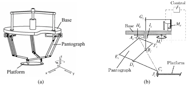
Mechanical architecture of PAMINSA. The first idea was to develop a parallel architecture whose displacements of the platform in the horizontal plane are independent of its vertical displacements. For this purpose, the pantograph linkage is used as a leg. The pantograph is a mechanical system with two input points Ai and Bi and one output point Ci. These input points
linearly control the displacement of the output point Ci. Thus one linear actuator connected with
input point Bi can control the vertical displacement of the output point Ci and one other linear
actuator with horizontal axis can control its horizontal displacements. Note please that these motions are completely decoupled, i.e. they can be carried out independently.
Now let us suppose that there is a concentrated mass in the point Ci. In this case the load of the
gravitational forces on the actuator of the horizontal displacements will be equal to zero (the gravitational forces are always perpendicular to the displacements). With regard to the actuator of vertical displacements, the load of the gravitational forces is not zero (the gravitational forces are parallel to the displacements). However, the input/output relationship for vertical displacement is linear and it is determined by the magnification factor of the pantograph. These properties of the pantograph mechanism are used in manipulators PAMINSA.
Now let us connect three Scheiner pantograph linkages with the base and the platform as it is shown in Fig. 1. In the obtained structure, one vertical actuator Mv controls the vertical
displacement of point Bi of the pantograph linkages, as a result, the vertical displacement of pairs Ci of the moving platform. The generation of motion in the horizontal plane is achieved by the
(a) (b)
Fig. 1. PAMINSA with 4-DOF (a); kinematic chain of each leg (b).
Thus, it is easy to see, that for the suggested architecture, the vertical translation of the platform along z axis is decoupled from its displacements in the horizontal plane (translations along x and y axes and rotation around z axis).
Among the obvious advantages of the suggested manipulator architecture, we would like to note the followings:
(i) the decoupling of the control powers in two parts, making possible to raise a heavy payload to a fixed altitude by powerful actuators and then to displace it on the horizontal plane by less powerful actuators;
(ii) a great accuracy in the horizontal positioning because the payload can be locked in the horizontal plane by mechanical architecture of the manipulator (in other words, if the position of the vertical actuator is fixed, the altitude of the platform cannot change);
(iii) the cancellation of the loads of gravity on the rotating actuators which displace the platform in the horizontal plane;
Table 1
Examples of motion generation of the input point Ai of pantograph linkages
Kinematic chain Planar representation 3D representation Type Schematics 3-RRR 3-RRR 3-RPR 3-RPR 3-RRP
3-PPR
3-PPR
3-PRR
3-PRR
It should be noted that motion generation of the input point Ai can be carried out by several
manners. All architectures shown in table 1 have the same properties mentioned above. The different schematics for input motion generation can be easily distinguished by the projection of the structure on the horizontal plane (the pair M’i – or H’i – corresponds to the displacement of
both pair Mi – or Hi – and pantograph linkage).
We considered above a basic structure of PAMINSA with 4 degrees of freedom (DOF). However, on the base of this approach, it is possible to obtain parallel manipulators from 3 to 6 DOF. Some properties of these manipulators were discussed in our previous works [12-14].
Let us consider the generalisation of the examined principle for a family of manipulators.
III. PAMINSA manipulators from 3 to 6 degrees of freedom
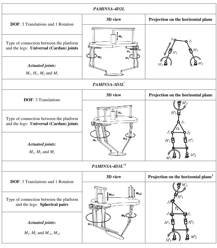
Table 2 shows PAMINSA manipulators from 3 to 6 degrees of freedom with a planar projection equivalent to a 3-RPR structure. Notation PAMINSA-iDjL means that the manipulator has i degrees of freedom and j legs. Table 2 also represents the output parameters, the actuated joints, as well as the type of connection between the platform and the legs. Such modifications can be easily extended to the other type of kinematic chains represented in table 1.
For each kind of manipulator, the rotations of the legs allow the horizontal displacement of the platform at a given altitude with given inclinations. Note please that the inclinations around x, y and z axes are obtained by the vertical translations of points Bi.
Each kind of PAMINSA has its advantages and can be used differently. Let us consider the particularity of each architecture. As it was mentioned above, the PAMINSA-4D3L allows improving the positioning accuracy along the vertical axis because the structure is kinematically locked during the displacement on the horizontal plane. Such a design allows the fixation of an important load in a given altitude, then positioning it on the horizontal plane.
Table 2. The family of PAMINSA manipulators with 3 to 6 DOF
PAMINSA-4D2L
DOF: 3 Translations and 1 Rotation
3D view Projection on the horizontal plane
Type of connection between the platform and the legs: Universal (Cardan) joints
Actuated joints:
M1, H1, M2 and Mv
PAMINSA-3D3L*
DOF: 3 Translations
3D view Projection on the horizontal plane
Type of connection between the platform and the legs: Universal (Cardan) joints
Actuated joints:
M1, M2 and Mv
PAMINSA-4D3L*2
DOF: 3 Translations and 1 Rotation
3D view Projection on the horizontal plane1
Type of connection between the platform and the legs: Spherical pairs
Actuated joints:
M1, M2 and Mv1, Mv2
*
Two of the three legs of such type of manipulator are actuated with the same motor and stay parallel to each other.
PAMINSA-4D3L
DOF: 3 Translations and 1 Rotation
3D view Projection on the horizontal plane1
Type of connection between the platform and the legs: Universal (Cardan) joints
Actuated joints:
M1, M 2, M 3 and Mv
PAMINSA-5D3L
DOF: 3 Translations and 2 Rotations
3D view Projection on the horizontal plane1
Type of connection between the platform and the legs: Spherical pairs
Actuated joints:
M 1, M 2, M 3 and Mv1, Mv2
PAMINSA-6D3L
DOF: 3 Translations and 3 Rotations
3D view Projection on the horizontal plane1
Type of connection between the platform and the legs: Spherical pairs
Actuated joints:
PAMINSA-4D2L is able to perform the same task as the PAMINSA-4D3L with only two legs. It should be noted that in this case the motorization is quite different.
PAMINSA-3D3L* can be used in any applications where only 3 translations along three axis are needed.
PAMINSA-4D3L* is useful for any task with 3 translations and one orientation about the x or y axis.
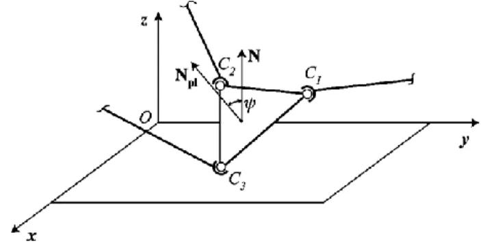
The PAMINSA-5D3L allows the carrying out of all displacements in the horizontal plane with an inclination angle of the platform (Fig. 2). The angle of the inclination can be defined as an angle between the normal Npl to the platform and the normal N of the plane xOy. Thus it is possible to move the platform on the horizontal plane with any inclination relative to the horizontal plane. In this case, the inclination is defined by the rotation of the point C3 about the line C1C2.
The PAMINSA-6D3L allows for any orientation of the platform about the z axis and the displacements of the platform on the horizontal plane. Two other inclinations of the platform are allowed.
We would like to note that for all versions of presented PAMINSA manipulators, there is a decoupling between the displacements on the horizontal plane and the other displacements.
As it was noted in the introduction, one of the drawbacks of parallel architectures is having more constraining singularity loci. The suggested manipulators are not devoid of this drawback. Let us consider the singular configurations of PAMINSA manipulators.
IV. Singularity analysis of PAMINSA manipulators
One of the important problems in the design of parallel mechanisms is the study of its singular configurations [15-27]. The singularity analysis, which will be presented, is carried out by Gosselin and Angeles approach [15], based on the properties of the Jacobian kinematic matrices of the mechanical structure, i.e. the singularity appears when the Jacobian matrices relating the input speeds and the output speeds become rank deficient.
We will present only the singularity analysis of PAMINSA manipulators which have a planar representation as 3-RPR manipulator. Singularity analysis for other types of PAMINSA can be carried out in the same way.
Fig. 3. Simplified schematic representation of the pantograph leg.
The singular configurations of PAMINSA manipulators can be separated into two cases: singularities of the pantograph linkage used as a leg and singularities of the simplified schematic representation of the manipulator in the horizontal plane by a kinematic chain PRPS (Fig. 3). The
pair H’i corresponds to the free translational displacement of both prismatic pair Hi and
pantograph linkage. The actuators M’vj correspond to actuator Mvj whose displacement is
amplified by the magnification factor of the pantograph. In PAMINSA manipulators, these singularities are not coupled and can be examined separately.
It may be noted that the singular configurations of pantograph linkage can be found by an analysis of the articulated parallelogram. They are well known and we shall not deal with them. The study below is only devoted to the singularities of the 3-PRPS parallel structure.
The Jacobian matrices of simplified parallel structure with 6-DOF appear in the form [15]:
0 Bt q A where k sym k k 0 0 0 0 0 0 0 0 0 0 0 0 0 0 0 3 2 1 A 0 1 0 0 0 1 0 0 0 1 0 0 0 cos sin 0 cos sin 0 cos sin 3 3 2 2 1 1 63 53 43 3 3 62 52 42 2 2 61 51 41 1 1 PC PC PC PC PC PC x y x y x y d d d d d d d d d B T Z Z Z , , ] , , , [ 1 2 3 1 2 3
q is the vector of the actuated joint rates (i corresponds to the rotation
of the motor Mi and Zi to the linear displacement of the motor Mvi for i = 1, 2, 3), t is the twist of
Table 3
Type 2 singular configurations of the family of the studied PAMINSA manipulators.
PAMINSA-4D2L
2 /
2
Small rotations of the platform about a vertical axis passing through J1.
PAMINSA-3D3L*
1 2n , n = 0, 1, 2… Free translation of the platform.
2 /
1
Small rotations of the platform about W (W is a vertical axis passing through the 3 wrenches Ri1).
PAMINSA-4D3L*
1 2n , n = 0, 1, 2… Free translation of the platform.
2 /
1
Small rotations of the platform about W (W is a vertical axis passing through the 3 wrenches Ri1).
2 /
Loss of inclination abilities of angle (front view of the manipulator)
PAMINSA-4D3L
2, 3 1n , n = 0, 1, 2… Free translation of the platform.
Small rotations of the platform about W (W is a vertical axis passing through the 3 wrenches Ri1).
Circle: 2 2 2 2 2 cos n b n b R RR R y x arccos(Rn/Rb) PAMINSA-5D3L 2, 3 1n , n = 0, 1, 2… Free translation of the platform.
Small rotations of the platform about W (W is a vertical axis passing through the 3 wrenches Ri1).
Conic: 5 5 5 5 0 2 5 2 5x By CxyDxE yF A 2 /
Loss of inclination abilities of angle (front view) PAMINSA-6D3L 2, 3 1n , n = 0, 1, 2… Free translation of the platform.
Small rotations of the platform about W (W is a vertical axis passing through the 3 wrenches Ri1).
Conic: 6 6 6 6 0 2 6 2 6x By C xyDxE yF A 2 /
Loss of inclination abilities of angle (front view)
2 2 ) ( ) ( Ci Oi Ci Oi i x x y y (i = 1, 2, 3) i PCi i z d4 cos (i = 1, 2, 3) i PCi i z d5 sin (i = 1, 2, 3) i PCi i PCi i x y d6 cos sin (i = 1, 2, 3)
As it was mentioned above the singularity of parallel manipulators appears when matrices A and B are rank-deficient. From these conditions we obtain:
3 2 1 3 ) det(A k ) 8 /( 27 ) det(B Rn3c 123
where is the expression of a conic given in appendix 1.
Thus Type 1 singularities appear, when i = 0 (i=1, 2 or 3), i.e. points Oi, Bi and Ci are aligned.
In such configuration, one rotation of the input link Mi cannot bring to the displacement of the
platform (Fig. 4).
Fig. 4. First type singularity.
Type 2 singularities of the manipulators PAMINSA from 3 to 6 DOF are represented in table 3 (in this table, parameters Rb and Rn represent the base and the platform radii respectively and
DOF, the input motions are combined and the study of the singularities of these manipulators can be carried out by studying the determinant of matrix B, in which the values of certain input/output parameters are fixed. Note please that all singular configurations for PAMINSA 4, 5, 6D-3L are found for the manipulators, in which the platform and the base are equilateral triangles.
Moreover, it could be demonstrated that, for the PAMINSA-4D3L, when the centre of the platform is on the circle defined by the expression x2 y2 Rb2 Rn2 2RbRn cos, the manipulator gains one finite motion defined as a Cardanic Self Motion [26].
Finally, the third type of singularity occurs when both A and B are simultaneously singular. The next section deals with the static/dynamic analyses and the optimization of a PAMINSA manipulator with 4 DOF.
V. Static/Dynamic analysis and optimization of the PAMINSA-4D3L
The static and dynamic modeling of the basic version PAMINSA-4D3L was presented in [12]. This section summarizes the obtained results and proposes a dynamic optimization based on the developed models.
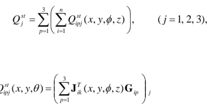
The static input torques (or forces) Qj applied to the actuators Mj (j = 1, 2, 3, 4) due to the force
of gravity of links, joints and platform of the studied manipulator can be expressed as:
) 4 , 3 , 2 , 1 ( , 3 1 1
j Q Q Q p n i st ipj st plj st j ,where is the load applied to the actuator j due to the gravity of the i-th link or bearings of the p-th leg (p = 1, 2, 3), is the load applied to the actuator j due to the gravity of the platform (Fig. 5).
j p ip T ip st ipj x y z x y z Q
3 1 ) , , , ( ) , , , ( J G Qplj
JTGpl
jwhere Jip is the Jacobian matrix between the point Pip and the actuated variables qj, Pip is the
center of masses of the i-th link, J is the general Jacobian matrix of the robot, between the point P and the actuated variables qj, P is the center of masses of the platform, G and Gip are respectively
the forces of gravity of the platform and the links (or bearings).
Fig. 5. Joints and links description for the static and dynamic analysis of the studied manipulator
It is easy to see that:
pl
j T pljQ J G =0, for j = 1, 2, 3.
i.e. the input torques of the rotating actuators due to the gravity of the platform are cancelled because the gravitational forces are always perpendicular to the displacements (the platform carries out the displacements in the horizontal plane).
It should be noted that, as the studied PAMINSA is symmetrical, the values of the input torques for the actuators are also symmetrical but they are situated in different zones (rotations of ±120°).
The input torques of the rotating actuators of examined manipulator are different from zero and their values depend on the altitude’s variations of the center of masses of each leg.
Thus, the input torques of the rotating actuators taking into account the mass distribution of each leg can be written as following:
), 3 , 2 , 1 ( , ) , , , ( 3 1 1
j z y x Q Q p n i st ipj st j where j p ip T ik st ipj x y x y z Q
3 1 ) , , , ( ) , , ( J GIt was also shown in [12] that the input torques due to the movable masses of the pantograph linkage can be cancelled by its optimal redistribution. Thus, by complete static balancing of legs, it should be possible to cancel the loads due to the movable masses of the legs on the rotating actuators.
Fig. 6. Variations of the actuator torques for z = -0.6 m and = 0° before (dark grey) and after (bright grey) static balancing of legs.
Fig. 6 shows the variations of the actuator torques before and after mass balancing. After complete static balancing the potential energy of the manipulator is constant for any
configuration and zero actuator torques are required. For example, the added masses are located at points 7p and their values are 2.8 kg (to observe the increase in masses after balancing, it
should be noted that the mass of each pantograph linkage before balancing was 3.1 kg).
It is obvious that such a balancing is very useful for static mode of operation of the manipulator. However with the increase of the accelerations of moving links, the inertia forces become important and the complete static balancing in dynamic operation can not be optimal. In this context another problem may be formulated: to find such a distribution of movable masses, which allows the minimization of the input torques of the rotating actuators in dynamic mode of operation.
In [12], we presented an analytic dynamic model of the manipulator PAMINSA-4D3L based on the Lagrange equations, which is used for above mentioned optimization.
The Lagrange function of the system was given in [12] as:
4 1 i ij i dyn j j j A Q q L q L t d dwhere i are the Lagrange multipliers (i = 1,…,4), qj are the generalized coordinates (j=1,…,8), Qj are the input torques or forces.
Coefficients Aij are obtained by differentiating the closure-loop equations of the manipulator
with respect to the generalized coordinates. Then the given system of equations is solved as follows: firstly the Lagrange multipliers must be obtained from the first four Lagrange equations and then the input torques/forces can be determined from the last four Lagrange equations.
For a comparative analysis of the unbalanced and statically balanced manipulators in dynamic operation we defined a prescribed trajectory given in appendix 2 (the numerical optimization is carried out for the link parameters of the manipulator given in [12]).
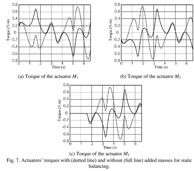
Fig. 8 shows the actuator torques in dynamic mode of operation for two cases: unbalanced and statically balanced manipulators. It should be noted that the added masses for complete static balancing do not allow the minimization of the input torques of actuators. Thus in the case of accelerated motions, it is better to achieve a partial balancing of masses.
(a) Torque of the actuator M1 (b) Torque of the actuator M2
(c) Torque of the actuator M3
Fig. 7. Actuators’ torques with (dotted line) and without (full line) added masses for static balancing.
The minimization problem can be expressed as the following:
ip ipr m dyn j Q , min max
i.e. it is necessary to find such a distribution rip of moving masses mip, which allows the
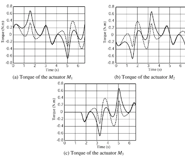
(a) Torque of the actuator M1 (b) Torque of the actuator M2
(c) Torque of the actuator M3
Fig. 8. Actuators’ torques with (dotted line) and without (full line) added masses for dynamic optimization.
In order to reduce the actuators’ torques, we use a numeric minimization. The obtained results are given in figure 8. Note please the added masses are located at points 7p (Fig. 5) and their
values are 1.3 kg.
The obtained results show that such optimization allows the reduction of the maximal values of the input torques in dynamic mode of operation to 45%.
We would like to note that the minimization was carried out for a prescribed trajectory. This trajectory may be either the generalized trajectory with maximum acceleration, which is generated by robot (for example, pick-and-place motion) or a trajectory, which is variable with
unknown parameters. In the first case the masses of the balancing counterweights can be constant and the influence of the trajectory variations on the torque minimization will be small. In the second case the balancing counterweights should be designed with adjustable parameters and they can be adapted to the given trajectory.
VI. Prototype and experimental validations
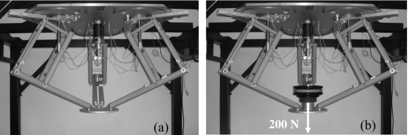
We have developed in the I.N.S.A. of Rennes a prototype of PAMINSA-4D3L whose planar representation is a 3-RPR manipulator (Fig. 9) [13]. The displacements on the horizontal plane of the developed prototype are obtained by Harmonic Drive motors connected with the legs by means of the toothed-belt transmission (Fig. 10).
Fig. 9. The prototype of PAMINSA-4D3L developed in the I.N.S.A. of Rennes.
For the actuator that controls the linear displacement of the vertical axes of the manipulator’s legs, the PARVEX motor system was chosen. The pantograph linkage has been carried out with double rods in order to improve the stiffness of the mechanical system. It is obvious that for an
industrial application it is an attractive approach to create a pantograph with single links and more rigid.
Fig. 10. Actuation system of each leg.
Validation of the design concept. In order to validate the suggested design concept, we have measured the input torques/efforts of the actuators with the payload of 200 N (Fig. 9b) and without it (Fig. 9a) for the trajectory given in figure 11. The obtained results are presented in figure 12.
The numerical simulations were validated by experimental tests. The curves with and without payload for the 3 rotating actuators (Fig. 12a, b, c) are superposed. We can see that they are similar, i.e. the loads on these actuators are cancelled. The small differences might result from friction in the joints, manufacturing errors, elasticity of the links and tracking errors.
Regarding vertical actuator (Fig. 12d), it supports the payload and increase of the input force is significant.
Fig. 11. Position of the platform for z = -0.6 m and = 0 °.
(a) Input torque of actuator M1. (b) Input torque of actuator M2.
(c) Input torque of actuator M3. (d) Input force of actuator Mv.
Demonstration of singularity. In order to demonstrate the previous results, we have positioned the PAMINSA prototype in a Type 2 singular configuration (x = 0 m, y = −0.25 m, = 0°). This
position is shown on Fig. 13(g). For such a configuration, the three actuators are blocked. However, it is possible to see on Figs. 13(a) to 13(e) that the platform is not constrained and undergoes a free motion when external force is applied to the platform. This free motion is a finite displacement of the platform on a portion of circle S with a rotation around a vertical axis.
Fig. 13. Type 2 singular configuration of the mobile platform of the PAMINSA prototype starting from the configuration x = 0 m, y = -0.25 m, = 0° (view from below).
Reduction of input torques in static mode of operation. The static balancing of the manipulator is experimentally accomplished by adding counterweights of 2.8 kg at the axis Fi of
In order to prove the minimization of input torques before and after balancing, some arbitrary configurations of the manipulator were examined. The tested poses are given in table 4.
Fig. 14. Counterweights added on pantograph linkages. Table 4
The poses for the experimental validation of the static balancing.
Pose x (m) y (m) z (m) (deg.) 1 0.124 0.096 -0.6 34.72 2 0.015 0.047 -0.615 -20.23 3 -0.149 0.009 -0.733 4.53 4 0.072 0.129 -0.497 9.23 5 -0.053 0.09 -0.540 33.92 6 -0.134 -0.075 -0.389 -3.5 7 -0.173 -0.042 -0.687 15.64 Table 5
The absolute values of the max. input torques before (case 1) and after (case 2) static balancing.
Pose Case 1 (N.m) Case 2 (N.m) Reduction
1 1.78 0.46 74 % 2 1.81 0.26 86 % 3 1.38 0.34 76 % 4 3.31 0.47 86 % 5 3.23 0.59 82 % 6 1.93 0.35 82 % 7 2.4 0.55 77 %
For these seven positions of the platform, the maximal absolute values of the input torques of the 3 rotating actuators before and after complete static balancing are measured (table 5). The reduction of the maximal input torques varies from 74% to 85%.
Reduction of input torques in dynamic mode of operation. For the trajectory given in appendix 2, we measure the input torques of the three rotating actuators for cases (without any payload and with the payload for dynamic mode of operation).
(a) Input torque of actuator M1. (b) Input torque of actuator M2.
(c) Input torque of actuator M3.
Fig. 15. Actuators’ torques without (full line) and with (dotted line) added masses for dynamic optimization.
Figure 15 shows the obtained results. The reduction of the maximal input torques with the added counterweight of 1.3 kg varies from 41% to 55%.
Thus, it can be noted that the obtained measures agree well with all above-mentioned numerical simulations carried out on the software ADAMS.
VII. Conclusion
In this paper, we have presented a novel motion decoupling technique for parallel mechanisms and its application to the design of a new class of decoupled parallel manipulators with high-load carrying capacity. The architectures of these manipulators called PAMINSA are built by legs, which are pantograph linkages. Manipulators from 3 to 6 degrees of freedom have been systematized and studied.
The reduction of the input torques has been also studied. It was shown that, for a dynamic mode of operation, the complete static balancing can not be effective in terms of input torques. In the case of accelerated motions, it is proposed to carry out an optimal redistribution of the movable masses and to achieve a partial mass balancing.
Finally, a prototype of PAMINSA with four degrees of freedom and experimental tests are presented. It is shown that the experimental tests prove the validity of the suggested design concept and the given numerical simulations.
The authors believe that the proposed manipulators could be used in industrial applications for the manipulation of heavy equipment with great positioning accuracy and little power consumption. Various fields are possible depending on the type of the industrial application.
It should be noted that the proposed manipulators have been patented [28] and additional information is available upon request.
References
[1] Terminology for the mechanism and machine science. Mechanism and Machine Theory, 38, pp. 597-605 (2003).
[2] B. C. Bouzgarrou, J. C. Fauroux, G. Gogu, Y. Heerah. Rigidity Analysis of T3R1 Parallel Robot with Uncoupled Kinematics. ISR-2004. Paris, France (2004).
[3] A. Yu, I.A. Bonev and P. Zsombor-Murray. New XY-Theta Positioning Table with Partially Decoupled Parallel Kinematics. IEEE International Symposium on Industrial Electronics (ISIE 2006), Montréal, Québec, 9–13 juillet, (2006).
[4] D. Bernier, J.M. Castelain & X. Li. A New Parallel Structure with 6 Degrees of Freedom. Proceedings of the 9th World Congress on the Theory of Machines and Mechanisms, Milan, Italy, pp.8-12, (2005).
[5] R. Di Gregorio. A New Decoupled Parallel Manipulator. Proceedings of the 10th International Workshop on Robotics, Vienna, Austria, May 16-18 (2001).
[6] J.P. Lallemand, A. Goudali and S. Zeghloul. The 6-dof 2-DELTA Parallel Robot. Robotica, vol. 15, pp. 407-416, (1997).
[7] M. Carricato and V. Parenti-Castelli. A novel fully decoupled 2-dof parallel wrist. The International Journal of Robotics Research, 23(6), 661–667 (2004).
[8] M. Carricato and V. Parenti-Castelli. On the topological and geometrical synthesis and classification of translational parallel mechanisms. Proceedings of the 11th World Congress in Mechanism and Machine Science, Tianjin, China, 1624–1628 (2004).
[9] X. Kong & C. M. Gosselin. A Class of 3-DOF Translational Parallel Manipulator with Linear Input - Output Equations. Workshop on Fundamental Issues and Future Research for Parallel Mechanisms and Manipulators, pp. 25-32. Quebec City, Quebec, Canada (2002).
[10] C. M. Gosselin, X. Kong, S. Foucault, & I. A. Bonev. A Fully Decoupled 3-DOF Translational Parallel Mechanism. PKM International Conference, pp. 595- 610. Chemnitz, Germany (2004).
[11] G. Gogu. Singularity-Free Fully-Isotropic Parallel Manipulators with Schönflies Motions. Proceedings of the ICAR International Conference on Advanced Robotics, July 18-20, pp. 194-201, (2005).
[12] V. Arakelian, S. Briot, S. Guegan. Static and dynamic analysis of the PAMINSA, Proceedings of ASME 2005 International Design Engineering Technical Conferences (IDET), 24-28 September, Long Beach, USA (2005).
[13] V. Arakelian, S. Briot, S. Guegan, J. Le Flecher. Design and Prototyping of New 4, 5 and 6 Degrees of Freedom Parallel Manipulators Based on the Copying Properties of the Pantograph Linkage, Proceedings of the 36th International Symposium on Robotics (ISR), 29 November – 1er December, Tokyo, Japan (2005).
[14] S. Briot, V. Arakelian. Singularity analysis of PAMINSA manipulator. 12thIFToMM World Congress, Besançon, France, 18-21 June, (2007).
[15] C.M. Gosselin, J. Angeles. Singularity analysis of closed-loop kinematic chains. IEEE Transactions on Robotics and Automatics. 6(3) pp.281-290 (1990).
[16] D. Zlatanov, R.G. Fenton and B. Benhabib. Singularity analysis of mechanisms and robots via a velocity-equation model of the instantaneous kinematics. Proceedings of the 1994 IEEE International Conference on Robotics and Automation, 2 pp. 980-991 (1994).
[17] J.-P. Merlet. Singular configurations of parallel manipulators and Grassmann geometry. The international Journal of Robotics Research. 8(5) pp. 45-56 (1989).
[18] B.M. St-Onge, C.M. Gosselin. Singularity analysis and representation of the general Gough-Stewart platform. The International Journal of Robotics Research. 19(3) pp.271-288 (2000).
[19] F. Pernkopf, M. Husty. Singularity analysis of spatial Stewart-Gough platforms with planar base and platform. Proceedings of the DECT 2002, Montreal (2002).
[20] J.T. Wen, J.F. Oapos Brien. Singularities in three-legged platform-type parallel mechanisms. IEEE Transactions on Robotics and Automation. 19(4) pp.720- 726 (2003).
[21] A. Wolf, E. Ottaviano, M. Shoham and M. Ceccarelli. Application of line geometry and linear complex approximation to singularity analysis of the 3-DOF CaPaMan parallel manipulator. Mechanism and Machine Theory, 39 (1) pp.75-95 (2004).
[22] S. Bandyopadhyay, A. Ghosal. Analysis of configuration space singularities of closed-loop mechanisms and parallel manipulators. Mechanism and Machine Theory, 39 (5) pp. 519-544 (2004).
[23] J.-S. Zhao, Z.-J. Feng, K. Zhou and J.-X. Dong. Analysis of the singularity of spatial parallel manipulator with terminal constraints. Mechanism and Machine Theory, 40(3) pp.275-284 (2005).
[24] V.A.Glazunov, A.Sh. Koliskor, A.F. Krainev, and B.I. Model. Classification principles and analysis methods for parallel-structure spatial mechanisms, Journal of Machinery Manufacture and Reliability, Allerton Press Inc., 1 pp. 30-37 (1990).
[25] I. Bonev, D. Zlatanov, C. Gosselin, Singularity Analysis of 3-DOF Planar Parallel Mechanisms via Screw Theory, Transactions of the ASME, Journal of Mechanical Design, Vol. 125, pp. 573-581 (2003).
[26] D. Chablat, P. Wenger, I.A. Bonev, Self motion of a special 3-RPR planar parallel robot, Advances in robot kinematics, Springer, pp. 221–228, (2006).
[28] Arakelian, V., Maurine, P., Briot, S., and Pion, E., 2006, Parallel robot comprising means for setting in motion a mobile element split in two separate subassemblies, WO 2006/021629, January 27th (2006). Appendix 1 6 6 6 6 2 6 2 6x B y C xy D x E y F A c s c c R c s R A6 2 b( )2 n , B6 2Rb(ccc ss)2Rnc, C6 2Rb(c 1)s() ) )) 2 ( 2 ) 2 1 ( )) 1 2 ( ) 1 ( 2 ( ( )) 3 4 ( ) ) 3 4 ( ) 4 1 )( 1 ( ( ( ( ) 1 ( ) ( 2 2 2 2 2 2 2 2 2 6 s R c c s c s c c s s c c c s c R R c c s c s c c c s c c R c D b b n n ) ) 1 2 ) 1 ( 2 ) 2 ) 4 2 2 ( ( ( )) 4 3 ( )) 4 3 ( ) 4 1 )( 1 ( ( ( ( ) 1 ( ) ( 2 2 2 2 2 2 2 2 2 2 6 c R s c s c c c c c c c c s c s c c R R c c c c c c c c s s c R c E b b n n 8 / ) 4 16 11 11 4 ( 8 / ) 4 18 6 6 4 8 ( 2 / ) 2 ( 4 / ) 7 ( ) 3 ( ) 2 ( ) ( ) 3 ( ) ( ) ( ) 2 2 ( 2 ) 2 2 2 ( ) 2 2 2 ( ) 2 2 ( ) ( 2 2 ) 2 2 ( 2 ) ( ) ( ) ( 3 3 3 6 c c c c c c c R R c c c c c c c R R c c c R c c R F b n b n b n 5 5 5 5 2 5 2 5 ) 0 ( Ax B y C xyD xE yF R c c R A5 2 b 2 n ,B5 2c(Rbc Rn),C5 2Rb(c 1)s, ) ) 1 ( ) 1 ( ( ) 1 ( 2 2 5 c R s c R R c c R s D n n b b ) ) 2 1 ) 1 ( ( )) 1 ( ( ( ) 1 ( 2 2 2 5 c R c c R R c c c R c E n n b b , )) 1 )( 1 ( ) ) 1 ( ) 1 )( 1 ( ( ) 1 ( ) 1 ( 2 3 3 2 2 2 2 2 2 5 c R c R c c R R c c c c c R R c c c c F n b n b n b .
Appendix 2
(a) Displacement along x-axis (b) Displacement along y-axis Fig. 18. The prescribed trajectory for z = -0.7 m and = 0°.
Figure captions
Fig. 1. To determination of the work of gravity in the horizontal plane and along the vertical axis. Fig. 2. Scheiner pantograph linkage.
Fig. 3. PAMINSA with 4-DOF (a); kinematic chain of each leg (b).
Fig. 4. The angle of the inclination of the platform for the PAMINSA-5D3L. Fig. 5. Simplified schematic representation of the pantograph leg.
Fig. 6. First type singularity.
Fig. 7. Joints and links description for the static and dynamic analysis of the studied manipulator Fig. 8. Variations of the actuator torques for z = -0.6 m and = 0° before (dark grey) and after
(bright grey) static balancing of legs.
Fig. 9. Actuators’ torques with (dotted line) and without (full line) added masses for static balancing.
Fig. 10. Actuators’ torques with (dotted line) and without (full line) added masses for dynamic optimization.
Fig. 11. The prototype of PAMINSA-4D3L developed in the I.N.S.A. of Rennes. Fig. 12. Actuation system of each leg.
Fig. 13. Position of the platform for z = -0.6 m and = 0 °.
Fig. 14. Input torques/effort on the actuators with and without an embedded load of 200 N. Fig. 15. Type 2 singular configuration of the mobile platform of the PAMINSA prototype starting
from the configuration x = 0 m, y = -0.25 m, = 0° (view from below).
Fig. 16. Counterweights added on pantograph linkages.
Fig. 17. Actuators’ torques without (full line) and with (dotted line) added masses for dynamic optimization.
Fig. 18. The prescribed trajectory for z = -0.7 m and = 0°.
Table captions
Table 1. Examples of motion generation of the input point Ai of pantograph linkages.
Table 2. The family of PAMINSA manipulators with 3 to 6 DOF.
Table 3. Type 2 singular configurations of the family of the studied PAMINSA manipulators. Table 4. The poses for the experimental validation of the static balancing.
Table 5. The absolute values of the max. input torques before (case 1) and after (case 2) static balancing.