OATAO is an open access repository that collects the work of Toulouse researchers and makes it freely available over the web where possible
Any correspondence concerning this service should be sent
to the repository administrator: tech-oatao@listes-diff.inp-toulouse.fr
This is an author’s version published in:
http://oatao.univ-toulouse.fr/21402
To cite this version:
Celis, Mayerling Martinez and Domengès, Bernadette and Hug, Eric and Lacaze, Jacques Analysis of Nuclei in a Heavy-Section Nodular Iron Casting. (2018) Materials Science Forum, 925. 173-180. ISSN 1662-9752
Analysis of Nuclei in a Heavy-Section Nodular Iron Casting
Mayerling Martinez Celis
1,a,*, Bernadette Domengès
2,b, Eric Hug
1,cand Jacques Lacaze
3,d1Université de Caen Normandie, ENSICAEN, CNRS UMR 6508 CRISMAT, 14032 Caen, France 2LAMIPS – CRISMAT - NXP semiconductors – Presto-Engineering Europe laboratory,
CNRS-UMR6508, ENSICAEN, UCN, Presto-Engineering Europe, 2 rue de la Girafe, 14000 Caen, France
3CIRIMAT, Université de Toulouse, ENSIACET, 31030 Toulouse, France
amayerling.martinez@ensicaen.fr, bbernadette.domenges@ensicaen.fr, ceric.hug@ensicaen.fr, djacques.lacaze@ensiacet.fr
* corresponding author
Keywords: nodular cast iron, heavy section casting, nuclei.
Abstract. The microstructure of heavy section nodular graphite cast irons often presents a bimodal distribution of nodule size associated with so-called primary and secondary graphite nucleation. It has been found that the nuclei in both types of nodules consist mainly in magnesium sulphide. However, nuclei in primary nodules contain some traces of calcium and are thus related with the inoculation treatment. On the contrary, nuclei in secondary nodules do not contain any element that could be associated to inoculation. It is suggested they form in the late stage of the eutectic reaction as a result of microsegregation build-up in magnesium and sulphur.
Introduction
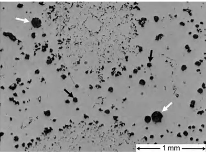
The microstructure of heavy section nodular graphite cast irons often presents a bimodal distribution of nodule size and some degenerate graphite precipitates. The largest nodules, generally called primary nodules, are expected to have precipitated early during the solidification process, either as true primary precipitates or during the early stage of the eutectic reaction. Smaller nodules, on the contrary, have certainly nucleated late during the eutectic reaction, they are called secondary nodules. Such a bimodal distribution is illustrated with the micrograph in Fig. 1 where also some degenerate primary precipitates and strings of chunky graphite are also observed.
Figure 1 – Optical micograph of a heavy section casting showing large "primary" graphite precipitates (white arrows) which are partly degenerated, small rounded "secondary" nodules (black arrows) and areas with strings of chunky graphite (on top and bottom middle areas of the image).
Owing to the long solidification time and the related inoculation fading, it can be expected that only the large primary nodules formed thanks to inoculant addition. On the contrary, smaller secondary nodules may have formed on nuclei precipitated during the solidification step. Their chemistry should then depend on microsegregation build-up and, in turn, their precipitation will affect the composition of the remaining liquid. That microsegregation during solidification can lead to formation of oxides or sulphides prone to trigger nucleation of graphite has often been mentioned doi:10.4028/www.scientific.net/MSF.925.173
in the literature and recently substantiated theoretically by Muhmond and Fredriksson [1]. However, this does not seem to have been challenged experimentally.
The aim of this work was thus the study of the crystallinity and composition of nuclei found in large and small nodules of an industrial heavy-section spheroidal graphite cast iron component. It was carried out using Transmission Electron Microscopy (TEM) technique. Due to the sub-micron size of the nuclei and their localization at the centre of the nodules, TEM lamellae were prepared using a Dual-Beam (Electron - Ga ion) system.
Material and Experimental Details
The material used in the present study was a piece machined out from a cubic test casting that had edges of 30 cm and solidified in 2.5-3 hours. All experimental melting details have been given previously [2] and the test used was referenced #18 in a previous publication [3]. Melts were prepared in medium frequency induction furnace of 15 tons capacity from pig iron and automotive steel scrap. Once melting was finished, the chemical composition of the metal was checked and adjusted if necessary. Two conditioners (or pre-inoculants) have been used in order to increase the nucleation ability of the melt, SiC and a commercial alloy based on FeSi2 (63.0 % Si, 8.3 % Ba, 1.4 % Al and 0.13 % Ca, in wt. %, balance Fe). The SiC was added into the furnace with the metallic charge whereas the FeSi2 alloy was added at the end of the melting procedure. Once the melt was ready, the spheroidizing treatment was carried out at about 1430ºC by adding FeSiMg alloy (45.0 % Si, 9.1 % Mg, 2.8 % Ca, 1.1 % RE and 0.9 % Al, in wt. %, balance Fe) using the sandwich method. After the spheroidizing treatment, the slag was removed from the melt surface, a sample was taken for chemical analysis and the iron was poured directly into the mould at a temperature of about 1380-1400ºC. Inoculation was performed by adding about 0.20 % of the weight of the metal of a commercial inoculant (70-78 % Si, 3.2–4.5 % Al, 0.3–1.5 % Ca and ~0.5 % RE, wt.% , balance Fe) in the form of ingots fixed with a foundry adhesive in the gating system of the mould. The chemical analysis which does not account for in mould inoculation gave the following composition in main elements (wt.%): 3.71 C, 2.07 Si, 0.034 P, 0.15 Mn, 0.038 Mg, 0.006 S and 0.0028 Ce.
TEM lamellae were prepared in a Dual-Beam system (FEI-HELIOS 600, Elstar Field Emission Scanning Electron Microscope column and Tomahawk Focused Ga Ion Beam column) equipped with Easy-lift manipulator designed for In-Situ Lift-Out thin lamella preparation. Energy Dispersive X-ray spectroscopy (EDS) elemental analysis system (OXFORD – AZTEC) is also available and allows in-situ, that is just after FIB preparation, elemental analyses on cross-section as well as on thin lamella, this ensuring a better spatial resolution.
TEM observations were performed on a JEM 2010 electron transmission microscope, equipped with a high tilting pole piece and allowing for imaging and electron diffraction studies.
Results
Fig. 1 shows an optical micrograph of the studied sample where can be seen large primary nodules (larger than 170 µm in diameter), small nodules (about 70 µm in diameter) and chunky graphite cells. From the outer shape of the latter, it may be inferred that the eutectic reaction took place in three steps [3]: i) primary nodules got surrounded by austenite leaving large areas of liquid; ii) chunky graphite cells nucleated and developed in these areas without being much limited by the first deposited solid; iii) finally, nucleation of secondary nodules took place in the remaining liquid and got soon encapsulated by austenite.
On one hand, a DualBeam system is probably the more appropriate technique to prepare TEM lamellae through the nodule nucleus, as it allows the observation of the cross-section plane with the electron column while grinding with the ion column through the nodule. On the other hand, it is not really adapted to such big samples (nearly 100 µm and over), the area of interest, that is the nuclei, being located at the almost centre of the nodules. Indeed, etching material several tens of microns deep requires to dig very large cavities (at least twice as deep) in the nodules and this is long time
consuming (several days). That is why, even for small nodules, mechanical grinding was first performed to get the surface sample closer to the diametrical section of the nodule as illustrated in (Fig. 2a). EDS analyses were then used to ensure that the nuclei were not too deep under the surface. The detection of Mg and S, using a 20 kV electron beam, appeared to be a reliable way to localize the nuclei (arrowed in Fig. 2a). FIB milling could then be performed directly on the observed sample. A 1 µm-thick strip of Pt was deposited onto the surface for protecting the selected area and milling of the first side of the lamella was then performed, till the nucleus was reached (arrowed in Fig. 2b). It is seen to be surrounded by graphite (dark contrast on the cross-section image). Then the thin lamella was prepared following the usual lift-out procedure [4].
Figure 2 – SEM micrographs of the centre of a small nodule cut in a near-diametrical section (a) and of the partly FIB-milled nodule during thin lamella preparation (b).
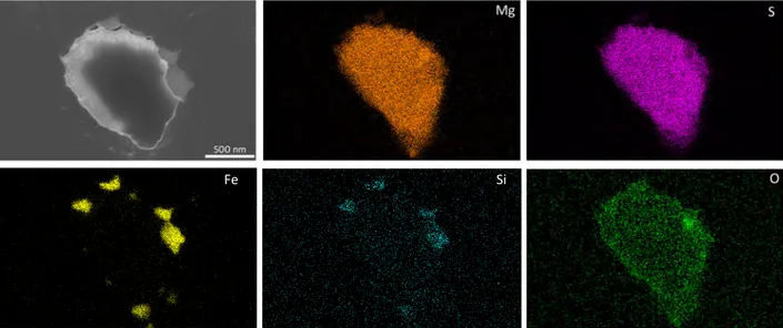
Once the thin lamella prepared, EDS analyses were performed in the DualBeam system, using a 20 kV electron beam. In order to characterize nuclei, distribution elemental maps could then be recorded and besides the surrounding C of graphite, Mg, S, Fe, Si and O were the main components found (Fig. 3). Al, Cu and Ni were also quite often detected but were disregarded as due to fluorescence from the copper grid supporting the lamella and the grid holder in the DualBeam.
Figure 3 – SEM micrograph of the nucleus of a small nodule and corresponding elemental maps of main components: Mg, S, Fe, Si and O.
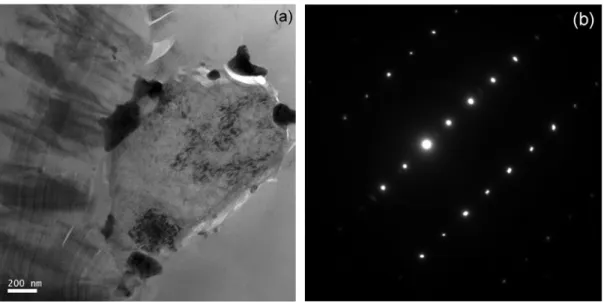
Most of the nucleus in Fig. 3 appears to consist in Mg and S with some O. The O-rich spot on the right side of the nucleus is also Mg rich with much lower S content. At the periphery of the nucleus, some other small spots are Fe – rich with some Si, but few O. Those appear as dark areas in the TEM bright field image of Fig. 4a and were found to be crystallized.
The selected area electron diffraction (SAED) pattern of the nucleus in Fig. 4b shows it is well crystallized, though precise identification of the crystalline phase was not possible. Note also that the imaging conditions were such that graphite layers are readily seen in the left part of the micrograph.
Figure 4 – TEM bright field image of the nucleus seen in Fig. 3 (a) and SAED pattern of the centre of the nucleus (b).
TEM observation of nuclei in other secondary nodules, such as the one in Fig. 5, confirmed that nuclei are composed of Mg, S and O, while the dark contrast areas at their periphery are Fe – rich with some Si, but few O. Contrary to the previous observation, this nucleus was composed of nanocrystals.
Figure 5 – TEM bright field image of a nucleus of another small nodule.
Looking for nuclei and preparing thin lamellae in large nodules proved to be much more difficult than in the case of small ones. This is because most of the large nodules are irregular in outer shape and show a huge number of metallic spots which do not always radiate from the centre. A quite regular large nodule is shown in Fig. 6a where graphite sectors are seen to be separated by rows of such metallic spots (arrowed), indicating that primary graphite was nearly prone to give exploded graphite in the investigated casting. This is made even more evident with the image in Fig. 6b which shows that the nucleus (empty arrow) is not fully surrounded by graphite. This nucleus was identified by EDS analysis performed on the cross-section, based on the presence of Mg and S elements.
Figure 6 – SEM micrographs of a large nodule as seen before (a) and after milling (b). Some metallic areas are arrowed in black in (a) and in white in (b).
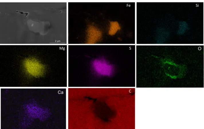
During completion of the TEM lamella preparation, EDS analyses were performed in the Dual-Beam system, using a 20 kV electron beam, at different thicknesses of the lamella: 900 nm thick foil (Fig. 7) and 200 nm thick (Fig. 8).
In Fig. 7, silicon was detected together with iron in the large metallic spots in contact with the nucleus. From the oxygen, magnesium and sulphur maps, it is seen that the nucleus consists in two phases, one containing mainly Mg and S with traces of Ca and might be MgS, and the other containing Mg and O and might be MgO. By contrast, it is worth stressing that calcium was not detected in the nuclei of small graphite nodules.
Figure 7 – SEM micrograph of the nucleus in a large nodule and corresponding elemental maps measured on the lamella 900 nm thick.
Elemental maps obtained on the lamella thinned to 200 nm are not so clear (Fig. 8). Considering the nucleus, MgS and MgO areas can be well distinguished, but some unexpected signal of Mg and S are superimposed with Fe – Si signal. Thus, some individual spectra were registered that showed this is probably an artefact related to automatic individual enhancement of map intensities on EDS images. These spectra also confirmed that traces of Ca are present in MgS particle.
Fe Si
Mg S
Figure 8 – SEM micrograph of the nucleus in a large nodule and corresponding elemental maps. This is the same lamella as in Fig. 6-7 after thinning to 200 nm. Given also, the EDX line profile across the nucleus. Note traces of Ca (dark blue) in Mg (orange)-S (pink) rich area.
It can be deduced from these maps, that the MgS particle is surrounded by a MgO shell, and that there is a MgO particle next to the sulphide.
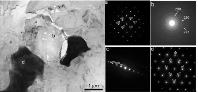
TEM analysis using electron diffraction allowed checking the crystallinity of and identifying various zones in and around the nucleus seen in Figs. 7 and 8. Fig. 9 shows a bright field TEM image and the SAED patterns corresponding to the zones identified with letters on the image. The MgS particle (zone a) is very well crystallized, with the [100] zone axis of cubic sulphide shown in the diffraction pattern labelled (a). The MgO particle (zone b) is composed of crystallized nanoparticles which are randomly oriented giving circles on the pattern. The inter-reticular distance calculated from the distance between the circles corresponds to the cubic structure of the MgO oxide. The almost amorphous microstructure of MgO oxide may be due to the thinning process in the DualBeam. Zone c corresponds to well-crystallized graphite, and iron particles (in black contrast) are crystalline, as confirmed by the diffraction pattern seen in (d) which corresponds to [111] axis zone of ferrite that also presents a cubic structure.
Fe Si
Mg S O
C
EDX line profile and corresponding evaluated atomic percent from acquired spectra in each point of the line
Figure 9 – Bright field TEM image of the same nucleus as in Figs. 8 and 9, and diffraction patterns of different locations: MgS (a), MgO (b), graphite (c) and cubic Fe-rich ferrite (d).
Discussion
The description made of Figs. 7-9 suggests the nuclei in large nodules in the studied alloy do not follow the most accepted schematic corresponding to a three-stage formation, oxide/sulphide/ complex oxide [5]. Further, detection of calcium in the sulphide of the nucleus (Fig. 7) confirms its formation was directly related to the inoculation treatment of the melt. In fact, other types of nuclei have been observed as reported in previous reviews [5-7] such as nitrides or else sulphides surrounding an oxide core similar to the ones seen in the small nodules of the present study (Fig. 3) and similar to those described by Igarashi and Okada [8]. That calcium was not detected in the nuclei observed in the small nodules shows that these nuclei certainly appeared during solidification because of microsegregation build-up of magnesium and sulfur in the remaining liquid.
Based on previous observations [9] and literature review, it has already been pointed out that nuclei may have a rounded shape and be amorphous [6]. In the present study, the rounded nucleus seen in Fig. 5 was found to be nano-crystallized but its external shape shows it should have been liquid during its formation. It was also pointed out that well-crystallized graphite starts growing in sectors right from the nucleus [10] and this was seen here also (Figs. 4 and 9). This shows that graphite can nucleate on any heterogeneous interface, were it be with a crystalline, nano-crystalline, amorphous or liquid particle.
A final remark relates to the Fe-rich particles found around the nuclei. In most cases, they are rather small as in Figs. 4 and 5 and are often enriched in strong desulfurizers and deoxidisers. It has been suggested they may appear by demixtion of the sulfur-rich liquid either before or after graphite had nucleated [8]. On the other hand, large particles as seen in Fig. 9 are much alike the particles at the boundary between radial sectors and are much closer in composition to the matrix. They must have formed together with graphite but could not grow further because coupled growth of austenite and graphite was hindered and overtaken by graphite precipitation.
Conclusion
In the investigated heavy-section nodular cast iron, it has been found that graphite nuclei consist mainly in both magnesium sulphide and magnesium oxide. However, they differ depending on the size of the graphite nodules they are found in. Nuclei in primary graphite nodules show large amount of both MgS and MgO, and they contain some traces of calcium and are thus clearly formed in relation with the inoculation treatment. On the contrary, nuclei in secondary nodules do not contain calcium, or any other element that could be associated with inoculation, and appear to
mainly consist in MgS. It is suggested they form in the late stage of the eutectic reaction as a result of microsegregation build-up in magnesium and sulphur.
Acknowledgments
This work was performed with the financial support of the program EQUIPEX GENESIS, Agence Nationale de la Recherche (ANR-11-EQPX-0020) for DualBeam system applications.
References
[1] H.M. Muhmond, H. Fredriksson, Relationship between inoculants and the morphologies of MnS and graphite in gray cast iron, Metall. Mater. Trans. B 44B (2013) 283-298.
[2] I. Asenjo, P. Larrañaga, J. Sertucha, R. Suárez, I. Ferrer, J. M. Gómez, J. Lacaze, Effect of mould inoculation on formation of chunky graphite in heavy section spheroidal graphite cast iron parts, Int. J. Cast Met. Res. 20 (2007) 319-324.
[3] J. Sertucha, R. Suarez, I. Asenjo, P. Larranaga, J. Lacaze, I. Ferrer, S. Armendariz, Thermal analysis of the formation of chunky graphite during solidification of heavy-section spheroidal graphite iron parts, ISIJ Int. 49 (2009) 220-228.
[4] T. Yaguchi, T. Kamino, T. Ishitani, R. Urao, Method for cross-sectional transmission electron microscopy specimen preparation of composite materials using a dedicated focused ion beam system, Microsc. and Microanal. 5 (1999) 365–370.
[5] T. Skaland, O. Grong, T. Grong, A model for the graphite formation in ductile cast iron: Part 1. inoculation mechanisms, Metall. Trans. 24A (1993) 2321-2345.
[6] J. Lacaze, Trace elements and graphite shape degeneracy in nodular graphite cast irons, Int. J. MetalCasting, 11 (2017) 44-51.
[7] G. Alonso, D.M. Stefanescu, P. Larranaga, R. Suarez, E. de la Fuente, Reassessment of nucleation models for spheroidal graphite through advanced SEM analysis, AFS Congress Proc., 2017, paper 17-031.
[8] Y. Igarashi and S. Okada, Observation and analysis of the nucleus of spheroidal graphite in magnesium-treated ductile iron, Int. J. Cast Met. Res. 11 (1998) 83-88.
[9] K. Theuwissen, M. Véron, L. Laffont, J. Lacaze, Crystallography of graphite spheroids in cast iron, Int. J. Cast Met. Res. 29 (2016) 12-16.
[10] K. Theuwissen, J. Lacaze, L. Laffont, Structure of graphite precipitates in cast iron, Carbon 96 (2016) 1120-1128.