DOCTORAT DE L'UNIVERSITÉ DE TOULOUSE
Délivré par :
Institut National Polytechnique de Toulouse (Toulouse INP)
Discipline ou spécialité :
Energétique et Transferts
Présentée et soutenue par :
M. LUCIEN GALLEN le mercredi 1 juillet 2020
Titre :
Unité de recherche : Ecole doctorale :
Prediction of soot particles in Gas Turbine Combustors using Large Eddy
Simulation
Mécanique, Energétique, Génie civil, Procédés (MEGeP)
Centre Européen de Recherche et Formation Avancées en Calcul Scientifique (CERFACS)
Directeur(s) de Thèse :
MME BENEDICTE CUENOT MME ELEONORE RIBER
Rapporteurs :
M. BENOIT FIORINA, CENTRALESUPELEC GIF SUR YVETTE M. HEINZ PITSCH, RHEINISCH-WESTFALISCHE TECH. HOCH.AACHEN
Membre(s) du jury :
M. BENOIT FIORINA, CENTRALESUPELEC GIF SUR YVETTE, Président M. ABDERRAHMAN EL BAKALI, UNIVERSITE LILLE 1, Membre
M. KLAUS PETER GEIGLE, GERMAN AEROSPACE CENTER BERLIN, Membre Mme BENEDICTE CUENOT, CERFACS, Membre
Mme ELEONORE RIBER, CERFACS, Invité M. NICOLAS BERTIER, ONERA, Membre
bustors is currently motivating considerable e↵orts to be better understand, model and predict soot formation. This complex phenomenon is very difficult to study in detail with experiment, and numerical simulation is an essential complementary tool. Consid-ering that the chemistry of soot particles strongly depends on their size, the numerical prediction of soot formation requires the description of their size distribution. To do so, either Eulerian methods (sectional or moments) or stochastic Lagrangian approaches are reported in the literature. In the present work, a far more simple semi-deterministic Lagrangian approach is proposed. An accurate description of the gaseous phase includ-ing first Polycyclic Aromatic Hydrocarbons is also developed as a necessary input to detail soot model. This work aims to develop a viable methodology of soot description within the LES framework. The manuscript is organized into three parts. The first part introduces the context and presents a literature review of soot particles focus-ing on numerical soot modellfocus-ing. Among the existfocus-ing method, the Lagrangian soot tracking is retained where additional developments are required to describe the particle size distribution (PSD). Then, the second part deals with laminar sooting flames. The modelling of reactive flow is briefly described, and the choice of chemistry modelling is also discussed in details. The Analytically Reduced Chemistry (ARC) is retained for the chemical description. Several ARC including PAH chemistry are selected, derived and validated on canonical laminar flames for di↵erent fuels, targeting di↵erent PAH. Lagrangian soot tracking has been developed and validated on canonic flames com-pared to a well-established method from the literature for which excellent agreement is found. The combination of ARC chemistries with Lagrangian soot tracking has been applied to investigate a set of canonic laminar flames analyzing soot global quanti-ties and PSD. Good predictions are obtained with the proposed methodology. Finally, the last part presents the soot prediction obtained with the proposed methodology in two complex configurations representative of an aeronautical combustors. The first one is the FIRST configuration, a gaseous confined pressurized swirled flame studied experimentally at DLR. Impact of precursors species and radiative transfers through the resolution of Radiative Transfer Equation (RTE). Good predictions are obtained compared to experiments for predicted temperature and soot volume fraction. The second target configuration is the UTIAS Jet A-1 burner and corresponds to a con-fined turbulent spray flame burning aviation jet fuel A-1 studied experimentally at UTIAS Toronto. LES of this configuration provides a qualitative and quantitative understanding of soot evolution in turbulent spray flames. Numerical predicted soot volume fraction using Lagrangian soot tracking and an ARC mechanism including py-rolysis method is compared to experimental measurements. Results show the ability of
measurements. In addition to an accurate soot model, the present work highlights the requirement of an accurate chemical description especially concerning soot inception as well as an accurate description of heat transfers for future investigation in turbulent flames.
ticules fines (PM), qui s’appliquent aux chambres de combustion de nouvelle g´en´eration n´ecessitent de nouvelles approches de conception. Afin de r´eduire la formation des par-ticules fines, ou parpar-ticules de suies, la compr´ehension des processus de formation et de transports des particules est n´ecessaire. La chimie et la dynamique de ces par-ticules de suies d´ependent fortement de la taille et de la morphologie de celle-ci. La pr´ediction de ces polluants requi`ere de prendre en compte la distribution en taille des particules tout au long du calcul. Pour cela, des m´ethodes Eul´eriennes sont utilis´ees (Moments,Sectionnels), ou des m´ethodes stochastiques Lagrangiennes sont propos´ees. Dans ce travail, une m´ethode semi-d´eterministique bas´ee sur l’approche Lagrangienne est propos´ee. Parall`element, une description pr´ecise de la chimie, notamment pour les pr´ecurseurs de suies n´ecessaire aux mod`eles d´etaill´es de formation de suies est d´evelopp´ee. Ce travail ambitionne de d´evelopper une m´ethodologie incluant la de-scription des pr´ecurseurs de suies et le transport de celles-ci dans le cadre de la sim-ulation aux grandes ´echelles. Le manuscrit est organis´e en trois parties. La premi`ere partie introduit le contexte de l’´etude ainsi qu’une revue d´etaill´ee de la litt´erature scientifique concernant les particules de suies et particuli`erement leur mod´elisation. Parmi les m´ethodes existantes, le suivi lagrangian des particules de suies est retenu dans ce travail. N´eanmoins de nombreux d´eveloppements additionnels sont n´ecessaires afin de mod´eliser avec pr´ecision la distribution en taille des particules. Ensuite la deuxi`eme partie s’int´eresse `a la mod´elisation des flammes laminaires et en particulier la pr´ediction des ´emissions de suies. La mod´elisation des ´ecoulements r´eactifs est rapi-dement ´evoqu´ee, le choix de la mod´elisation de la chimie de combustion est ´egalement discut´ee. Le choix de la chimie analytiquement r´eduite (ARC) est retenu dans ce tra-vail. Le d´eveloppement et la validation de sch´emas cin´etiques r´eduits pour di↵´erents carburants ainsi que di↵´erents pr´ecurseurs de suies est d´etaill´e. Enfin, la m´ethode du suivi Lagrangien des particules de suies est d´ecrite en d´etails et valid´ee par rapport `a la litt´erature. La combinaison des chimies r´eduites ARC et du suivi Lagrangien des partic-ules est utilis´ee sur plusieurs flammes canoniques pour lesquelles de bonnes pr´edictions de suies sont obtenues. Finalement, la derni`ere partie pr´esente la pr´ediction des suies obtenue avec notre m´ethodologie dans deux configurations de type a´eronautiques. La premi`ere est la configuration FIRST, il s’agˆıt d’une flamme ´etudi´ee au DLR op´erant `
a haute pression dans un milieu confin´e et stabilis´ee `a l’aide d’un swirleur. L’impact du choix du pr´ecurseur de suies ainsi que la prise en compte des transferts radiatifs est ´evalu´ee. La temp´erature et la fraction volumique des suies sont en accord avec les mesures exp´erimentales. La seconde configuration est le bruleur UTIAS Jet A-1 o`u le Jet A-1 est un carburant a´eronautique, il est caract´eris´e par une flamme swirl´ee
particules des suies dans les flammes turbulentes diphasiques. Un tr`es bon accord avec les donn´ees exp´erimentales est observ´e pour cette configuration concernant les partic-ules de suies. Le travail de cette th`ese souligne la n´ecessit´e d’une description pr´ecise de la chimie, notamment celle des pr´ecurseurs de suies, ainsi qu’une description pr´ecise des transferts de chaleur pour la pr´ediction des particules de suies dans les bruleurs de type-a´eronautiques.
I would like to thank B´en´edicte Cuenot and Eleonore Riber for o↵ering this PhD thesis opportunity within the European project SOPRANO. I also would like to thank all SOPRANO members, in particular Benedetta Franzelli and Klaus Peter Geigle for their help and discussions all along the PhD thesis as well as for SOPRANO PhD student like Livia, Kevin and Martin and the others for fruitful discussions. Moreover I would like to thank Heinz Pitsch and Benoˆıt Fiorina for examining my work and the other members of the jury, Abderrahman El Bakali, Nicolas Bertier, Klaus Peter Geigle and Gorka Exilard for their positive and relevant comments. Ce travail a ´et´e r´ealis´e sous la direction de B´en´edicte et Eleonore, qui m’ont guid´e tout au long de mon travail. Je les remercie d’avoir eu confiance en moi et mon travail et de m’avoir permis de garder une grande autonomie. Merci aux s´eniors CERFACS qui ont contribu´e d’une fa¸con ou une autre `a ce travail, je pense en premier lieu `a Antony qui a toujours pris le temps de m’expliquer en d´etails tout un tas de choses, un grand merci ´egalement `
a Gabriel et Olivier pour leur aide et leur savoir-faire que j’ai si souvent sollicit´e. C’est ´egalement le cas d’Isabelle et de tout l’´equipe CSG. Je re-mercie surtout leur p´edagogie sur la r´esolution de mes probl`emes qui m’ont ´enorm´ement appris. Merci ´egalement `a l’´equipe administrative, Mich`ele, Chantal, Marie, Nicole et Jade, pour leur efficacit´e et gentillesse. Merci `a Thierry ´egalement pour l’´energie qu’il transmet `a cette ´equipe (CFD).
Durant mon passage au CERFACS, j’ai eu la chance de rencontrer un grand nombre de coll`egues qui ont d’une mani`ere ou d’une autre contribu´e `a ce tra-vail mais surtout `a une bonne ambiance de travail. Merci `a Jarjar, Bastien, Nico et F´elix de m’avoir mis le pied `a l’´etrier d`es le d´ebut. Merci `a l’En Avant Cerfacs (EAC) et tous ces membres pour les bons moments partag´es, `
a son capitaine embl´ematique Maxou et g´en´erosit´e extraordinaire (hors du terrain seulement), `a Valou le goal/coach au top, aux anciens membres Majd le tricot, Dario le 9, Kelu le magnifique, Biolchi et Pedro avec leur tirs/d´egagements hors norme jusqu’au nouveau avec l’´equipe dirigeante dou-teuse men´ee par Christopher et David et tous ces membres qui en font un
Catchi. Et beaucoup d’autres en dehors de l’EAC, Bastien, Astoul, Gau-thier, Flo’ que l’on retrouve plutˆot autour d’une mousse.
Plus r´ecemment apr`es avoir eu F´elix comme exemple de bonne conduite et de rigueur, merci `a mon nouveau co-bureau, le stagiaire, la male ou Maxicuisse d’avoir pris ma direction plutˆot, merci pour les bons moments pass´es et d’avoir supporter mes fractures du mental en sortie r´ecup’ comme tu dis. Merci `a tout l’´etage: Charl´elie, Fabien, Quegui, Juju, le bureau Arcane ! Et finalement merci `a Etienne qui prend la suite et qui `a la fin `
a contribu´e `a ce travail grˆace `a son efficacit´e sur le code chimique et `a nos diverses discussions.
Finalement un immense merci `a ma grande et petite famille pour leur pr´esence et leur soutien sans faille.
I Context of the study 7
1 Introduction 9
1.1 Global context: combustion-generated pollutants . . . 9
1.2 E↵ect of PM from aircraft engines on health and climate . . . 12
1.3 Aeronautical burner design: status and constraints . . . 14
1.4 Need and challenges for numerical simulations of pollutant emissions . . 16
1.5 Objectives and structure of the PhD thesis . . . 18
2 Soot formation and its modeling 21 2.1 Soot morphology and internal structure . . . 21
2.2 Soot formation and oxidation mechanism . . . 28
2.3 Numerical methods for soot prediction . . . 35
II Numerical developments and validation for soot prediction in flames 49 3 Modeling of laminar reactive flows 51 3.1 Laminar flames . . . 51
3.2 Conservative equations for gaseous reacting flow . . . 57
3.3 Equations for reacting two-phase flow . . . 66
4 Lagrangian soot tracking methodology 75 4.1 Lagrangian formalism for soot prediction . . . 76
4.2 Numerical methods . . . 77
4.3 Evaluation of LST efficiency . . . 83
4.4 Conclusion . . . 89
5 Analytically Reduced Chemistry with accurate soot precursors pre-diction 91 5.1 Chemical kinetics of ethylene-air flames with accurate PAH chemistry . 92 5.2 Derivation and validation of an ARC for ethylene-air flames with accu-rate PAH chemistry . . . 98
5.3 Prediction of larger PAH for ethylene-air flames . . . 104
5.4 Extension to aviation jet fuel chemistry . . . 112
6 Lagrangian Soot Tracking in laminar flames. 117
6.1 Detailed soot modeling . . . 117
6.2 Bi-variate description of soot particles . . . 123
6.3 Physical and numerical validation . . . 125
6.4 Laminar flames: comparison with experiments . . . 130
6.5 Conclusion . . . 142
III LES of sooting flames 143 7 Modeling of turbulent reacting flows 145 7.1 Turbulent Flames . . . 146
7.2 Large Eddy simulation . . . 150
7.3 Turbulence - Chemistry interactions . . . 153
7.4 Thermal radiation modeling in turbulent sooting flames . . . 158
8 LES in a confined pressurized burner 167 8.1 The FIRST combustor . . . 167
8.2 Numerical set-up . . . 169
8.3 Results . . . 172
8.4 Computational cost . . . 205
8.5 Conclusion . . . 208
9 LES in a turbulent spray flame 211 9.1 UTIAS Jet A-1 combustor . . . 211
9.2 Numerical setup . . . 212
9.3 Results . . . 214
9.4 Computational cost . . . 224
9.5 Conclusions . . . 226
10 Conclusions and perspectives 227
Bibliography 231
Appendices 269
A Article on Lagrangian soot tracking methodology 271
C Coupling procedure AVBP-PRISSMA 283 C.1 Coupling libraries . . . 283 C.2 Coupling communications . . . 283 C.3 Coupling time step . . . 284
Roman characters
Symbol Description Unit
a Strain rate [s 1]
c Flame progress variable [-]
dl Liquid droplet diameter [m]
Dk Di↵usion coefficient of species k [ ]
E Gaseous total energy per unit mass [J/kg]
E Efficiency function [-]
Fd,i Volumetric force vector of particle drag [N/m3] Fp,i Drag force vector of a Lagrangian particle [N]
F Thickening factor [-]
hs Sensible enthalpy [J/kg]
HRR Heat Release Rate [W/m3]
Jj,k Di↵usive flux vector of species k [kg/m2/s]
K Flame curvature [m 1]
Lv Latent heat of evaporation [J/kg]
mp Mass of a Lagrangian particle [kg]
˙
mp Rate of change of droplet mass [kg/s]
˙
mp Mass flux of gaseous fuel from a droplet [kg/s] ˙
m Mass flux [kg/s]
nF Number of points in the flame front [-]
nl Number of droplet density [m 3]
P Pressure [Pa]
P Probability density function [ ]
q Momentum flux ratio [ ]
r Mixture gas constant [J/kg/K]
˙rj Rate of reaction j [mol s 1]
R Universal gas constant (mass) [J mol 1K 1]
Sij Strain rate tensor [s 1]
t Time [s]
T Gaseous temperature [K]
ui Gaseous velocity vector [m/s]
ul Eulerian liquid phase velocity [m/s]
up,i Velocity vector of a Lagrangian particle [m/s]
W Molecular weight [kg/mol]
xi Spatial coordinate (vector) [m]
x Spatial coordinate (vector) [m]
x Spatial coordinate [m]
xp,i Position vector of a Lagrangian particle [m]
Xk Molar fraction of species k [ ]
y Spatial coordinate [m]
Yk Mass fraction of species k [ ]
z Spatial coordinate [m]
Greek characters
Symbol Description Unit
↵l Liquid volume fraction [ ]
Scalar dissipation rate [s 1]
ij Kronecker symbol [ ]
⌘ Kolmogorov scale [m]
l Rate of change per unit volume of the liquid phase mass [kg/m3/s] Rate of mass change per unit vol. in the gas phase by evap. [kg/m3/s] u,i Momentum exchange through mass exchange [kg/m2/s2]
Flame stretch [s 1]
Heat conduction coefficient [W/m/K]
µ Molecular viscosity [Pa s]
µt Turbulent viscosity [Pa s]
Equivalence ratio [-]
⇧g Sensible enth. rate of ch. per unit vol. in the gas phase by evap. [W/m3] ⇧l Sensible enth. rate of ch. per unit vol. in the liq. phase by evap. [W/m3]
⇢ Gaseous density [kg/m3]
⇢k Density of the gaseous species k [kg/m3]
⇢l Liquid phase density [kg/m3]
⌧ij Stress tensor [N/m2]
⌧ijt Turbulent tress tensor [N/m2]
⌧p Particle relaxation timescale [s]
c
g Sensible enth. rate of change in the gas due to conduction [W] ev
g Sensible enth. rate of change in the gas due to evaporation [W] ev
l Sensible enth. rate of change in the liq. due to evaporation [W] c
l Sensible enth. rate of change in the liq. due to conduction [W]
l Liquid volume flux [m3/s/m2]
˙!k Species source term (in mass) of species k [kg/m3/s] ˙!Yk Species source term (divided by density) of species k [s
Dimensionless numbers Symbol Description
BM Spalding number for mass transfer BT Spalding number for heat transfer Le Lewis number
N u Nusselt number P r Prandtl number
P rt Turbulent Prandtl number Re Reynolds number
Ret Turbulent Reynolds number Rep Particle Reynolds number Sc Schmidt number
Sh Sherwood number St Stokes number W e Weber number
Indices and superscripts Symbol Description
g Index of a gaseous phase quantity l Index of a liquid phase quantity p Index of a solid phase quantity F Index of a fuel quantity
glob Index of a quantity at global equivalence ratio O Index of an oxidiser quantity
st Index of a quantity at stoichiometric equivalence ratio tot Superscript of an integrated quantity
Acronym Definition
ARC Analytically Reduced Chemistry CDSM Chemical Discrete Sectional Method CFD Computational Fluid Dynamics CFL Courant-Friedrichs-Lewy CMC Conditional Moment Closure CRZ Central Recirculation Zone DNS Direct Numerical Simulation DOM Discrete Ordinate Method
DQ Direct Quadrature Method Of Moments DRG Directed Relation Graph method
DRGEP DRG with Error Propagation DSM Discrete Sectional Method
DTFLES Dynamically Thickened Flame model for LES FIM-UR Fuel Injection Method by Upstream Reconstruction
FPI Flame Prolongation of Intrinsic Low-Dimensional Manifold GRC Globally Reduced Chemistry
HACA Hydrogen Abstraction Carbon Addition HMOM Hybrid Method Of Moments
IRZ Inner Recirculation Zone ISL Inner Shear Layer LES Large Eddy Simulation LST Lagrangian Soot Tracking LOI Level Of Importance LW Lax-Wendro↵
MOM Method Of Moments
MOMIC Method Of Moments with Interpolative Closure NDF Number Density Function
NSCBC Navier-Stokes Characteristic Boundary Conditions ORZ Outer Recirculation Zone
PAH Polycyclic Aromatic Hydrocarbons PDF Probability Distribution Function PEA Pre-Exponential Adjustment PIV Particle Image Velocimetry
PLIF Planar Laser-Induced Fluorescence PSD Particle Size Distribution
PSDF Particle Size Distribution Function PSR Perfectly Stirred Reactor
PVC Precessing Vortex Core QSS Quasi-Steady State QSSA QSS Approximation
RANS Reynolds Average Navier-Stokes RMS Root-Mean-Square
ROS Reactive Oxygen species
RQL Rich-burn, Quick-Quench, Lean-Burn RSR Resonantly-Stabilized Radicals RTE Radiative Transfer Equation TF Thickened Flame
TFLES Thickened Flame model for LES
Introduction
Contents
1.1 Global context: combustion-generated pollutants . . . 9 1.2 E↵ect of PM from aircraft engines on health and climate . 12 1.3 Aeronautical burner design: status and constraints . . . 14 1.4 Need and challenges for numerical simulations of pollutant
emissions . . . 16 1.4.1 Soot prediction in aeronautical burners: the SOPRANO project 18 1.5 Objectives and structure of the PhD thesis . . . 18 1.5.1 Organisation of the manuscript . . . 19 1.5.2 Brief introduction of the target configurations . . . 20
1.1
Global context: combustion-generated pollutants
The global demand in energy has been increasing continuously from decades driven by a robust global economy and higher heating and cooling needs in some parts of the world. In response to that high demand, the world’s total energy supply which is almost exclusively based on combustion processes burning fossil resources, is still increasing as observed in Fig. 1.1a. Relying on practical combustion devices implies several policy dealing with energy independence, human health and environment. The exhaustion of fossil fuels and the environmental pollution thus generated by combustion is in itself a major preoccupation. This finding has been globally recognized for few years however fuel depletion, growing pollution and global warming still continue. Figure 1.1b highlights the rising levels of CO2 emissions for di↵erent fossil fuels which contribute to global warming. In 2017, transport accounted for nearly one quarter of direct CO2 emissions from fuel combustion (Fig. 1.2). Road vehicles were responsible for nearly three-quarters of transport CO2 emissions followed by aviation and shipping sectors which both continue to rise. It can be observed on Fig. 1.3 that the world aviation annual traffic will double in just 15 years. In response to a significantly increase in air traffic, regulatory measures have been adopted by many countries to impose a drastic reduction of pollutant emissions and fuel consumption. For example, in 2017, it adopted CO2emissions standards were adopted for airplanes, to be enforced by national aviation authorities. These standards aim to limit the emissions of newly designed aircrafts.
(a) World total primary energy supply (Mtoe) from 1971 to 2017 by source.
(b) CO2 emissions (Mt) from 1971 to 2017 by fuel.
Figure 1.1: World total primary energy supply by source (a) and CO2 emissions by fuel (b) from 1971 to 2017 (Extracted from International Energy Agency (IEA) 2019)
Figure 1.2: Rescaled direct CO2 emissions by sector and by transport mode, data
ex-tracted from IEA 2019
Figure 1.3: International Civil Aircraft Organization (ICAO) air traffic data and Airbus traffic forecast in revenue passenger kilometers (trillion unit). From [1].
Figure 1.4: Emissions from a typical two-engine jet aircraft during 1-hour flight with 150 passengers (extracted from the European Aviation Environmental Report 2019 ), and their impact (adapted from the European Aviation Environmental Report 2019, Masiol et al. [3] and Lee et al. [4]).
Of course, CO2 emission is not the only target of regulations. Incomplete com-bustion products such as carbon monoxide (CO), unburnt hydrocarbons (HC), sulfur dioxide (SO2), nitrogen oxides (NOx), or poly-cyclic aromatic hydrocarbons (PAHs), and soot particles also contribute significantly to global warming. These pollutants pose significant and growing threats to the environment and human health as depicted in Fig. 1.4 which quantifies the mean pollutant emissions for a typical two-engine jet aircraft during 1-hour flight with 150 passengers. Each of them a↵ects both the envi-ronment and human health in their own way increasing the relevance to regulate all of them. Stringent regulations have already been adopted for CO2, noise, CO and NOx emissions and regulations for Particulate Matter (PM) and PAHs are expected for the coming years [2].
PAHs, depicted as HC in Fig. 1.4, are an important class of organic pollutants, because of their toxic e↵ects on ecosystem and harmful e↵ects for human health [5]. In addition to these negative e↵ects, PAHs are soot precursors by means of radical addition reactions on double bonds, cyclization, and formation of resonantly stabilized radicals resulting in incipient soot [6]. Particulate matter (PM) and PAHs emissions from aircraft engines are produced as a result of incomplete combustion of organic materials in fuel-rich and high-temperature environments. As depicted in Fig. 1.4,
these emissions a↵ect global climate, local air quality, and public health in a direct or indirect way.
1.2
E↵ect of PM from aircraft engines on health and
cli-mate
PM are considered as aerosol and one of the most prominent groups of toxic air pollu-tants related to health e↵ects, as being therefore of international concern today. PM are divided into two main classes of ambient air pollution particles depending on their diameter [7]. The first class is composed of coarse particles with diameter below 10µm (PM10), defined as inhalable particles. The second class contains fine particles with di-ameter smaller than 2.5µm (PM2.5), defined as respirable particles. However, recently another size class has been defined for ultra-fine particles smaller than 0.1µm (PM0.1). Particle size is important for its lifetime in the atmosphere and its airways deposition. As a consequence PM classification is considered to be one of the best indicators for health e↵ects from air pollution and will be used for further regulations [8]. As parti-cle size decreases, deposition occurs deeper in the respiratory system. Partiparti-cles a↵ect both the pulmonary and cardiovascular systems. Soot particles contribute to numerous adverse health impacts including :
• airway inflammation • asthma aggravation
• impairment of pulmonary defence mechanisms • lung cancer
• heart arrhythmia
Recent epidemiological, human and animal model studies have shown that soot par-ticles can trigger the formation of reactive oxygen species (ROS), which may cause oxidative stress, cell death, biological aging and diseases. Once formed into lungs, ROS cause damage to deoxyribonucleic acid (DNA), proteins, tissues, lipids; etc. [9]. They are of additional concern because of their ability to pass through cell walls and rapidly enter the blood stream due to their size close to virus size as shown in Fig. 1.5. Im-mune responses can be a↵ected by these particles, which drive pro-allergic inflammation through the generation of oxidative stress [10].
In addition to health concerns, aircraft also a↵ects climate through CO2 emissions (Fig. 1.4) and a number of non-CO2 climate forcing agents that are unique to this sector of transportation including soot particles and SO2. According to the Intergovernmental
Figure 1.5: Size range of atmospheric aerosols and hydrometeors. (Extracted from [9])
Figure 1.6: Processes influencing the contrail formation stage. (Extracted from [15])
Panel on Climate Change (IPCC) [11], these forcing agents accounted for nearly 4% of the global radiative forcing from all human activities in 2011, and represent the largest aviation radiative forcing component. PM emissions impact climate in three di↵erent ways. First, the black carbon component of PM is a strong light absorber, it directly contributes to climate forcing by absorbing solar radiation and increasing atmospheric temperatures [12]. Second, black carbon deposition on snow and ice accelerates melt-ing [13]. Third, PM emissions alter the radiative properties and lifetime of clouds [14]. Additionally, the PM emitted from aircraft turbine engines at high altitudes act as vapor condensation nuclei initiating contrails and cirrus clouds [15]. While CO2 emis-sions contribute to climate change on long time scales (about centuries), contrails a↵ect environment on short time scale (about hours for long-lived contrails).
In Fig. 1.6, the aerosol particle types present in aircraft exhaust plumes are shown to comprise emitted soot particles, nanometre-sized aqueous aerosol particles formed within the plumes and particles mixed into the plumes from the ambient air. In the jet regime, these particles interact with condensable vapours (water vapour mainly) and ionised gas molecules. The di↵erent particle types compete for supersaturated vapour in water droplet formation, highlighted in grey. For aircraft emissions, soot particles figure most prominently in droplet formation. These droplets freeze and grow rapidly by uptake of water vapour forming a visible contrail. The contrail formation
happens when the ambient temperature falls below the formation threshold determined by the Schmidt-Appleman criterion [16]. Plumes from multiple aircraft engines merge with two wing tip vortices, forming an inhomogeneous wake. The further evolution of ice crystals depends largely on fluid-dynamical processes, in the vortex regime. The downward motion of the vortex pair warms the air causing ice crystal sublimation in the lower wake. Ice crystals present in the upper wake continue to grow by uptake of entrained ice-supersaturated ambient water vapour. Few minutes past emission in the dissipation regime, the organised flow pattern collapses and mixes with ambient air.
Soot particles promote the formation of contrails and contrail cirrus which reflect solar radiation and trap outgoing terrestrial radiation resulting in a net positive radia-tive forcing [17]. The average e↵ect of contrails on the earth’s radiation budget, on radiative forcing and climate, depends on their global coverage and mean optical thick-ness. Both quantities are not well known and numerical modelisation is a valuable tool to reduce uncertainties about the global e↵ect of contrails. Although the conditions for contrail formation can be fairly well predicted [16], the impact of contrails on radiative forcing strongly depends on the evolution of the number concentration, the size and the shape of ice crystals within the plume (see Fig. 1.6) which are not taken account in contrail formation models [18]. Soot particles provide a large number of potential ice nuclei that will influence contrails and induced cirrus clouds optical properties [15, 18]. Nowadays, uncertainties in soot particle emission indices in cruise regime which are sensitive to operating conditions, engine type, and even fuel composition [19] are one of the main problems to evaluate the radiative potential impact of contrails.
As a result, legislation is becoming more stringent for particulate emissions. The EU air quality directive defines the PM2.5concentration of 25µg/m3on an annual basis and will lower a threshold to 20µg/m3 by 2020 [2].
1.3
Aeronautical burner design: status and constraints
Many practical combustion devices, especially aircraft engines, operate locally in non-ideal burning conditions that lead to incomplete combustion and result in the produc-tion of carbonaceous compounds. This is mainly due to local hot spots, insufficient mixing of fuel and oxidizer or liquid fuel atomizing of liquid fuels, or too short resi-dence time at high temperatures. Of course, pollutants are formed in the propulsion system which is the most expensive part of the aircraft, representing up to 1/3 of the final aircraft cost. Moreover, the increasing cost of kerosene makes fuel consumption reduction another determinant challenge. Both aspects make the engine a key point of the current aeronautical challenge. Conventional double-flux gas turbines currently
Figure 1.7: Sketch of a conventional double-flux gas turbine engine.
Figure 1.8: Sketch of a conventional RQL combustion chamber (Extracted from [20])
used in civil aircraft is illustrated in Fig. 1.7. The air entering the primary flux by the fan is pressurized by the low and high pressure compressors to optimize the thermody-namic cycle. In the combustion chamber, air is rapidly mixed with liquid kerosene that evaporates and the fresh gas mixture burns, producing very hot combustion products at high velocity. These accelerated hot products then transfer their kinetic energy to high and low pressure turbines before being released through the nozzle. The turbine drives the compressor and the fan thanks to axial shafts, which is the main role of the primary flux. The major part of the engine thrust is produced by the action-reaction principle: the secondary flux is ejected at a much higher velocity than at intake thanks to the energy transfer from the fan to the secondary flux gases. A zoom of a conven-tional combustion chamber called Rich Burn, Quick-Mix, Lean Burn (RQL) system is proposed in Fig. 1.8. It is generally divided in three zones: a primary zone (coloured in red in Fig. 1.8), an intermediate zone (blue zone) and a dilution zone (yellow zone). Soot particle formation occurs mainly in the primary zone, close to the fuel spray, where fuel and air are not well mixed[21, 22]. The intermediate zone reduces gas temperature to an intermediate level by the addition of a small amount of air to promote the
com-Emissions
Altitude
reignition
Thermal
efficiency
Stability
Thermoacoustic
stability
Figure 1.9: Design constraints applying to aeronautical burners.
plete oxidation of carbon monoxide and soot particles by oxidation. The dilution zone provides an outlet stream with a temperature distribution acceptable to the turbine, but encouraging NOx formation.
From the combustor design point of view, the dual objectives of fuel efficiency and pollutant emissions are contradictory. Higher core engine thermal efficiency requires higher operating pressure and temperature of the combustor, which directly promotes soot emissions. As depicted in Fig. 1.9, the design of aeronautical combustion cham-bers is constrained by high safety and operability requirements over the whole flight envelope, as well as drastic weight and size constraints compared to land gas turbines. Thus the development of low emission innovative design must result from a global optimisation process.
The ICAO has also developed a regulatory standard for non-volatile Particulate Matter emissions from turbofan and turbojet aircraft engines with a rated thrust greater than 26.7 kN [8]. Although the regulatory standard is based on soot number and mass emissions, these properties alone are not sufficient for evaluating the air-quality, health, and climate impacts of soot emissions. Regulatory standards will have to take into account particle size, reactivity and morphology to provide a more e↵ective regulatory policy.
1.4
Need and challenges for numerical simulations of
pol-lutant emissions
Given the expected stringent regulatory policies on aircraft engines and the constraints in terms of safety and operational requirements illustrated in Fig. 1.9, the combination of experimental campaigns and numerical tools like Large Eddy Simulation (LES) are of great help for a better understanding of the combustor behaviour and underlying mechanisms [23, 24].
In the last decade, LES have shown their capacity to correctly capture most un-steady features, such as fuel-air mixing, ignition and flame dynamics [24, 25, 26, 27] and has been able to accurately predict pollutants like CO and NOx [28, 29, 30, 31]. Although the chemical processes for CO and NOx are rather well understood and char-acterized (compared to soot), their accurate prediction in real aeronautical geometries remains a challenge due to the complex turbulent spray flame in the multiphase com-bustion, turbulence, air cooling and dilution, or radiative and wall heat transfer.To understand pollutant formation in real combustors, it is necessary to consider first aca-demic configurations, well characterized by many measurement techiniques. Indeed, in real systems at real operating conditions, no optical access is possible and measure-ments are often limited to exhaust gas composition.
Predicting soot emissions is even more ambitious since chemical and physical pro-cesses are only partly known and must be better understood. Current knowledge of soot formation has been derived from three types of work [6]:
• Experimental : Measurements of soot volume fraction fv, soot number density Ns and particle size distribution (PSD) typically expressed as dN/dlog(dsoot).
• Chemical : Development of both detailed chemical mechanisms for the formation of soot precursors and detailed soot chemistry models.
• Numerical : Development of soot population dynamics models to describe the evolution of the particle ensemble.
All of them are required to predict accurately soot formation using LES. First, chem-ical mechanisms including accurate PAHs, which are highly reactive and difficult to detect (low levels) compared to classical pollutants, are of crucial importance in soot modeling as a necessary input. Then, a reliable soot chemistry model, where a lot of uncertainties remain, is used to compute soot evolution coupled with an adequate numerical methods to transport soot particles. Finally, thorough validations against experimental measurements are required before computing complex configurations.
Concerning soot prediction in complex configurations, most of the modeling e↵ort relied for a long time on semi-empirical approach [32] by transporting only soot mass fraction and number density, these methods relied on manyl assumptions and corre-lations from experimental observations. Although efficient in terms of numerical cost, these methods only give access to a mean soot particle diameter and are however not able to describe soot formation from one configuration to the other with the same set of constants. An alternative to semi-empirical methods for soot prediction is to consider
PSD, relying mainly on either complex mathematical methods to account for particle polydispersity or stochastic approaches where all soot processes are calculated by prob-ability. These methods, more accurate, can be difficult to implement and can require considerable numerical resources in their execution.
1.4.1 Soot prediction in aeronautical burners: the SOPRANO project
This PhD has been supported by the H2020 project SOPRANO (SOot Processes and Radiation in Aeronautical inNOvative combustors) 2016-2020. This industrial and academic research project aims at providing new elements of knowledge, analysis and improved design tools, opening the way to alternative designs of combustion systems for future aircraft capable of simultaneously reducing gaseous pollutants and particles, and improve the liner lifetime. Therefore, the SOPRANO project will deliver more accurate experimental and numerical methodologies for predicting the soot emissions in academic or semi-technical combustion systems. This will contribute to enhance the comprehension of soot particle formation and their impact on heat transfer through ra-diation. In parallel, the durability of cooling liner materials, related to the wall air flow rate, is addressed by heat transfer measurements and predictions. Finally, the expected contribution of SOPRANO is to apply these developments in order to determine the main promising concepts, in the framework of current low-NOx technologies, able to control the emitted soot particles in terms of mass and size over a large range of oper-ating conditions without compromising combustor’s liner durability and performance toward NOx emissions.
To this purpose, a comprehensive numerical methodology for soot prediction has been developed, based on the solver AVBP developed by CERFACS. This methodology relies on detailed chemistry for the gaseous phase, a semi-deterministic Lagrangian approach to transport soot particles in complex configurations and the development of coupling strategy to solve Radiative Transfers Equation (RTE) in order to evaluate soot production in aeronautical burners.
1.5
Objectives and structure of the PhD thesis
Over the past decades, CERFACS has developed an expertise in Computational Fluid Dynamics (CFD) and more specifically in LES with the solver AVBP1. AVBP has been continuously improved by students and senior researchers, and has been successfully employed to study a wide range of turbulent flow applications, in relatively complex geometries. Historically, semi-empirical models [32, 33, 34, 35] were used to evaluate soot production using AVBP. As said in Sec. 1.4, these models based on empirical
constants have shown their limits. There is a consensus however in the soot community that PSD must be take into account to correctly capture soot evolution. Moreover, soot size is critical for associated health and environmental concerns and should be take into account in future PM emissions regulations.
The available computational power is constantly increasing and the use of more accurate soot models is becoming a↵ordable [36, 37, 38]. The main objective of this thesis is to investigate on the capabilities of a semi-deterministic Lagrangian approach for soot prediction in terms of accuracy; and to confront this approach to the existing techniques in terms of computational cost. Another objective is to combine a detailed soot model to an Analytically Reduced Chemistry (ARC) [39, 40], which ensures a good description of the flame structure and dynamics and species involved in the soot model considered.
1.5.1 Organisation of the manuscript
The manuscript is organised as follows:
• Part I: This part provides a brief overview of the pollutant emissions and some concerns regarding their negative e↵ects in Chapter 1. In Chapter 2, mechanisms for soot particle formation and soot experimental characterization are discussed together with the soot modelling methods available in the literature.
• Part II: This part focuses on modeling of turbulent reactive flows as well as the numerical methods developed and implemented in this work. In Chapter 3, the theoritical concepts of combustion are described, and the sets of equations solved for both the gas and liquid phases are given. The Chapter 4 presents the Lagrangian Soot Tracking approach with a simple soot chemistry model and its evaluation in a complex geometry. Then Chapter 5 details the selection of the appropriate chemical schemes for the fuels considered in this PhD, from gaseous C2H4 to liquid aviation jet fuel Jet A1, with a special attention to soot pre-cursors. Finally, the proposed Lagrangian Soot tracking approach with a more sophisticated soot chemistry model is detailed and validated in canonical flames configurations (Chapter 6 ).
• Part III: The third part focuses on performing, validating and analysing LES of turbulent sooting flames. LES and reactive models involved in such computa-tions are defined in Chapter 7. Two turbulent sooting flames are then studied: a confined pressurized sooting ethylene-air swirled flame in Chapter 8 and an atmospheric Jet A-1-air sooting spray flame in Chapter 9. For both cases, soot formation and particles size distributions dynamics are analyzed.
1.5.2 Brief introduction of the target configurations
The operating conditions for two target configurations will be widely employed through-out the first chapters of the thesis to build and validate the di↵erent models. For the clarity of the reader, they are briefly introduced at this early stage:
• The FIRST confiuration is a swirled pressurised combustor operated with ethy-lene. The combustor burns in a lean, non-premixed regime. The selected operat-ing point operates under overall lean conditions ( glob= 0.86), the primary com-bustion zone being characterized by an overall rich equivalence ratio ( prim= 1.2). It operates under moderate pressure P = 3 bars with secondary air injection, fuel and air are supplied at Tin= 300 K.
• The UTIAS jet A-1 burner is a swirled turbulent spray flame configuration burning kerosene fuel. The combustor operates at ambient conditions P = 1 bars, Tin = 300 K.
Soot formation and its modeling
In this chapter, generalities about soot formation and its modeling are discussed. First soot particle is described in terms of morphology. Then the soot formation mechanisms and their impact on soot particles are detailed.
Second, the basis of numerical methods is introduced and the di↵erent modeling approaches are summarised. The selection of the retained soot model, the Lagrangian soot tracking approach, is discussed.
Contents
2.1 Soot morphology and internal structure . . . 21 2.2 Soot formation and oxidation mechanism . . . 28 2.2.1 Mechanisms involved in soot formation . . . 28 2.2.2 Soot growth . . . 31 2.2.3 Soot oxidation and fragmentation . . . 34 2.3 Numerical methods for soot prediction . . . 35 2.3.1 Governing Equations . . . 36 2.3.2 Numerical approach . . . 39 2.3.3 Choice of the numerical method . . . 46
2.1
Soot morphology and internal structure
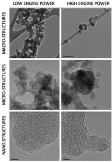
Soot di↵ers from other pollutants in its composition. Contrary to CO2, CO or NOx soot is a carbonaceous material containing thousands or millions of carbon atoms. The transition from fuel containing a few carbon atoms to a solid carbonaceous agglomerate is a complex physical and chemical process. A typical morphology of such a material from aircraft combustion devices is shown in Fig. 2.1. It is obtained from Transmission Electron Microscopy (TEM) analysis of soot particles which is the preferred method for direct characterization of aggregate structure. Soot aggregate is shown to be composed of primary particles with a chain-like structure [41]. The primary particles are near-spherical in shape with a diameter in the range of 10 nm to 80 nm [6, 42, 43, 44, 45]. The primary soot particles are made of about 104 numbers of crystallite structures, observed by High Resolution Transmission Electron Microscopy (HRTEM) [41, 46]. HRTEM images in Fig. 2.2 highlight the di↵erent levels of structure describing soot particles for two engine powers (low 4 7% and high 100% of the maximum thrust). First row shows
Figure 2.1: TEM images of soot aggregates emitted from a SaM146 engine at di↵erent thrust levels. a) 30% of the maximal thrust b) 70% of the maximal thrust c) 85% of the maximal thrust d) 100% of the maximal thrust. (Extracted from [18])
the aggregate size, the macro-structure. Second row displays the primary particle size, the micro-structure. The third row represents the nano-structure within the individual primary particle composed of crystallite structures. This crystallinity arises due to the stacking of planar PAH indicating that PAHs are soot precursors [41]. The bottom part of Fig. 2.2 shows a succession of hollow centers highlighting the presence of an amorphous structure using HRTEM. This amorphous structure arises from the random alignment of aromatic structures [46]. Figure 2.3 shows a schematic of the formation of such amorphous structures [47]. The clustering of PAHs (nanostructure) forms the incipient soot particle with a spherical shape forming a nucleation mode in terms of PSD (Mode-I in Fig. 2.3). The incipient soot particle is a primary particle (microstructure), then aggregation promote the formation of soot fractal-like aggregates (macrostructure) that vary widely in size and shape. These soot aggregates are responsible for the second mode of the PSD. The presence of such soot aggregates and the persistent nucleation in rich flames both explain the bimodality of the soot PSD. In most cases soot particle is described at the macro-scale through its volume v and its surface area s. At micro-scale, soot particle is composed of np primary particles with the same primary particle diameter dp [48]. The relation between macro and micro structures can be expressed
Figure 2.2: HRTEM images of derived soot macro - micro - and nano-structures; left column images are for low engine power level (4 7% of the maximum thrust) and right column images are for high (maximum thrust)engine power. (Extracted from [46])
Figure 2.3: Schematic crystallite structure in soot nucleation and growth. (Extracted from [47]) as follows: ⇢ dp = 6vs np= s 3 36⇡v2 (2.1)
It can be noted that a spherical particle, such as an incipient particle can also be described as an aggregate with np = 1 and dp = d = (6v/⇡)1/3. However, these char-acteristics are not sufficient to describe soot aggregate structures. Those are typically characterized by a power law relationship, np / (dc/dp)Df, where the number of pri-mary particles is proportional to the ratio of the collision diameter dc of an aggregate to the primary soot particle diamete dpr and the fractal dimension Df, which is about 1.8 for soot aggregate [49, 50, 51, 52]. The collisional diameter dc, also called gyra-tion diameter in the literature, is essential to describe collisional phenomena of soot aggregates. Following the definition of np, the collisional diameter reads :
dc / dpn1/Dp f (2.2) In addition to a complex internal structure, soot morphology is a↵ected by many pa-rameters that are listed below together with their impact on soot morphology.
• E↵ect of pressure on soot morphology: Pressure has been shown to sig-nificantly influence soot concentrations in di↵usion flames [53]. Recently, Vargas et al. [54] have investigated pressure influence on soot PSDF and morphology, showing that the soot number density increases with increasing pressure. Mea-surements at elevated pressure indicate that the e↵ect of pressure is to increase
Figure 2.4: TEM images of soot aggregates at 2.3 atm (A), 4 atm (B), 5.4 atm (C), 7.1 atm (D), and 10 atm (E). (Extracted from [55])
the number of incipient soot particles, also called soot nuclei and to decrease the primary particle size as shown in Fig. 2.4. The increase of soot number density can be explained by the reduction of particle collision rate with increasing pres-sure. The decrease of particle size is attributed to the reduction in the hydrogen radical concentration with increasing pressure leading to reduced soot surface growth, which will be detailed in Sec. 2.2.
• E↵ect of temperature on soot morphology: Temperature plays a crucial role in soot formation, especially high temperature environment which promotes soot formation. Experimental studies have shown that soot volume fractions from various fuels exhibit a ”bell-shaped’ curve as a function of temperature in both shock tubes and laminar premixed flames [56, 57, 58]. It has been highlighted that flames at low temperature favor soot bimodality with large soot aggregates [57],
Figure 2.5: TEM images of soot incipient (a,c) and mature soot (b,d) for high flame temperature (top: a,b)and low flame temperature (bottom: c,d). (Extracted from [59])
while flames at high temperature favor unimodality of the soot PSDF. Apicella et al. [59] investigated the soot properties in laminar premixed ethylene flames at di↵erent flame temperatures. TEM images of both incipient and mature soot for high and low flame temperature are shown in Fig. 2.5. For both high and low temperature flames, the nanostructure for mature soot is similar. However, it was found that nascent soot formed at low flame temperature is more hydrogenated, reactive and less aromatic while soot nuclei formed in the higher temperature flame undergoes enhanced dehydrogenation and aromatization processes.
• E↵ect of fuel on soot morphology: The fuel composition plays an important role in the nanostructure of soot. In laminar premixed flame, soot formed from aromatics (benzene) were found to have a core organized structure compared to ethylene [60], as shown in Fig. 2.6. This was explained by the flame environment containing a higher concentration of smaller PAHs including benzene, compared to aliphatic flames (ethylene). In addition, the small content of light hydrocar-bons avoids their intrusion on the particle nuclei limiting the degree of disorder in the soot [61]. Recently, fuels of practical interest have been investigated in terms of soot properties. In a premixed flame [62], surrogate mixtures of m-xylene/n-dodecane and n-butanol/n-m-xylene/n-dodecane (oxygenated) have been studied. A similar structure has been observed for each fuel, however the mixture of n-butanol/n-dodecane presented a greater loss of structure and a much higher oxidation rate.
Figure 2.6: TEM images of young and mature soot for ethylene and benzene fuel. (Ex-tracted from [60])
For a better understanding, Botero et al. [63] developed an image analysis code in order to quantify the structure of soot particles from HRTEM images. The morphology and nanostructure of soot particles were investigated in liquid-fuelled di↵usion flames, varying the fuel: heptane, toluene, a commercial gasoline and an iso-volumetric heptane-toluene mixture. The main di↵erences in the soot struc-ture were the arrangement and the degree of order of the aromatic strucstruc-tures within each particle. For typical kerosene fuel, the impact of distillate fractions on soot was investigated showing a strong impact on premixed stretch-stabilized flames [64]. Indeed, the decomposition of such complex fuel via pyrolysis and evaporation process (for liquid fuel) a↵ects directly the soot morphology. In-formation on the morphology and nanostructure of practical fuels or surrogates remain scarce and are of great importance to understand sooting phenomena.
Pressure, temperature and fuel characterize di↵erent structures and a↵ect soot reac-tivities, which is crucial for determining its toxicity [65]. Practical combustion devices evolve typically under these conditions, i.e., high pressure, high temperature and burn-ing kerosene (complex) fuel generatburn-ing large macro-structures [18]. Actually, these conditions impact mainly soot processes, which must be identified, and then change the morphology evolution. Physical and chemical processes involved in soot morpho-logical evolution are described in this chapter.
Figure 2.7: Schematic representation of soot evolution. (Adapted from [66])
2.2
Soot formation and oxidation mechanism
The formation and evolution of soot particles in flames are the result of complex mech-anisms including both chemical and physical processes. These processes, illustrated in Fig. 2.7, include: initial gas-phase reactions, gas to condensed-phase transition corresponding to particle nucleation, particle mass and size growth through coagula-tion/coalescence, heterogeneous surface reactions and condensation of gaseous species and particle oxidation reactions, when oxygen is available in the flame. The whole mechanism takes place at high temperature and with a time scale of the order of a few milliseconds. Therefore, understanding the soot formation process in combustion is a great challenge.
2.2.1 Mechanisms involved in soot formation
2.2.1.1 Soot precursors formation
The soot formation process starts with the chemical decomposition reactions of fuel molecules. Successively, pyrolysis and then oxidation of the fuel lead to the formation of smaller carbon species, such as acetylene (C2H2). The contribution of C2H2 to aromatics formation via the H-Abstraction, Acetylene addition (HACA) mechanism was proposed in [67]. Then, the important contribution of resonantly-stabilized radicals (RSR) such as propargyl radical (C3H3) has been shown in the formation of the first
Figure 2.8: HACA mechanism between benzene and naphthalene. (Extracted from [70])
Figure 2.9: Conceptual mechanisms of soot particle nucleation: A) Fullerenic mechanism ; B) Dimerization process ; C) PAH addition (Extracted from [6])
aromatic, benzene (C6H6 ⌘ A1) [68]. It is a key precursor since it is the first aromatic species and therefore the starting point of PAH and consequently of soot formation. Like for benzene formation, the HACA mechanism plays a key role in the formation of PAH [67, 69]. The HACA mechanism comprises two repetitive steps, which are first the abstraction of hydrogen atom forming a radical, and second the addition of acetylene on the radical site. This mechanism is illustrated in Fig. 2.8 for the naphthalene (C10H8) formation starting from benzene. Similar to benzene formation, RSR contribute to PAH formation, which has been confirmed experimentally [71, 72, 73] and theoretically [74, 75].
2.2.1.2 Soot nucleation
As discussed in Sec. 2.1 , HRTEM reveals that soot are mainly composed of PAHs, which are then considered as the dominant class of precursors . Soot nucleation characterizing the transition from gaseous phase to solid phase is probably the less known process of soot formation. Various hypothetical pathways for soot nucleation have been suggested [6]. These conceptual pathways are depicted in Fig. 2.9 and discussed hereafter.
• Fullerenic mechanism: It concerns the evolution of stacked PAH together with presence of five-rings aromatics that can bend the structure into curved
fullerene-like structures as illustrated in Fig. 2.9A. The consumption of such structures was observed [76] and attributed to their interactions with the abundant small carbon species to form soot. However, this hypothesis was discarded since almost no large molecules of fullerene-like can be found in the flame environment and this mechanism is too slow compared to soot inception.
• PAH dimerization: According to Frenklach and Wang [77], soot nucleation was explained to occur through physical colliding PAHs, leading to the formation of PAH dimers. This dimerization process is a pathway explaining soot inception in high-temperatures regions as shown in Fig. 2.9B. Schuetz and Frenklach [78] attempted to understand the non-equilibrium dynamics of dimerization process performing molecular dynamics simulation on the collision of pyrene under flame conditions. Their work has confirmed the dimerization compatibility as soot formation pathway in terms of chemical timescale.
• PAH addition: This nucleation process, shown in Fig. 2.9C), is linked to the chemical growth of nascent soot from PAH species. This growth mechanism proposed by D’Anna and coworkers [79], also involves PAH coalescence as the dimerization process. The continuous mass and size growth of three-dimensional, cross-linked, ring-ring aromatic structures leads to the properties of nascent soot. The repetitive reaction sequences involved in this pathway can be depicted by :
Ai+ H ⌦ Ai + H2 (R2.1) Ai + Aj ⌦ Ai+j+ H (R2.2) where Aiand Ai represent the PAH species and its radical respectively. Subscript i, j or i + j refers to the size of PAHs. This mechanism explains a variety of chemical structures as a result of collisions with di↵erent PAHs. However, this mechanism cannot explain the persistent particle nucleation into the post-flame region [57], where the presence of H atoms, is not sufficient to trigger soot formation.
These conceptual pathways, often used for soot modeling (especially the PAH dimer-ization), still cannot explain the transition from gas phase to solid phase. In ad-dition to these conceptual pathways, Johansson and coworkers [80] proposed a new mechanism called the clustering of hydrocarbons by radical-chain reactions (CHRCR) mechanism that involves a sequential reaction of RSR, involved in benzene and PAH formation. Each sequence in this mechanism forms a more stable RSR and further sustains the mechanism. It initiates with repetitive additions of C2H2, C2H3 leading to small resonant species, such as C3H3 or C5H5. The growth reaction generates new
RSR with increasingly higher molecular weights. And this mechanism does not require H-abstraction, it is independent of the presence of H atoms and may explain soot for-mation in post-flame regions [57] contrary to previous conceptual pathways. However, this mechanism is not yet available and to test this hypothetical mechanism, there is a need to establish detailed reaction rates for the many reactions between RSR and other radical and stable hydrocarbon species as well as, the formation of an initial cluster of soot particles and the growth [81].
Meanwhile, P AH dimerization is widely used to model soot nucleation and accepted by the soot community.
2.2.2 Soot growth
Once soot particles have been formed by nucleation, the total amount of soot is mainly due to soot growth [82] occurring via several processes:
• Surface growth: surface growth by acetylene • Condensation: chemical growth by PAHs • Coagulation: collision of soot particles
Surface growth and condensation increase the total soot mass while coagulation controls the number of soot particles and the particle size.
Surface growth
Surface growth consists in the incorporation of gaseous species to the surface of pre-existing soot particles [83]. It implies an increase of primary particle diameter dp and then of soot volume fraction without any change in soot particle number. It acts through carbon addition at the surface of soot particles, and C2H2 is considered as the main species involved in this carbon addition. The analogy between chemical reactions taking place at PAH surface and those occurring at soot surface has been proposed by Frenklach and Wang [69]. Similarly to benzene and PAH formation, the HACA mechanism is characterized by the following reaction:
Sc+ H ⌦ Sc⇤+ H2 (R2.3)
Sc⇤+ H ! Sc (R2.4)
Sc⇤+ C2H2 ! Sc+2+ H (R2.5) where Sc and Sc⇤ refer to a soot particle with c carbon atoms and its associated radical respectively. Reaction R2.3 represents the function of Sc⇤ from Sc by the abstraction of a hydrogen atom at the soot surface. Reaction R2.4 is the associated deactivation
reaction. Finally, C2H2 addition occurs in Reaction R2.5 where C2H2 reacts with Sc⇤ surface at high temperatures [69]. However the initial HACA mechanism is known to have di↵erent limiting regimes [84].
However the initial HACA mechanism is known to have di↵erent limiting regimes [84]. A numerous extension to HACA mechanism have been proposed to extend its validity range with di↵erent set of Arrhenius parameters [85, 86, 87] or with additional reactions [88, 89, 90] or to add species to contribute to H-abstraction [91, 92, 93, 94].
Zhang et coworkers [95] proposed an alternative to HACA mechanism in the low-temperature regime based on C2H2 addition to a hydrogenated aromatic site followed by H Migration (CAHM) that should be more favorable below 1500K in the fuel rich post-flame region. Recently, the progress of quantum and reaction-rate theories enables to improve kinetics and thermodynamics of the HACA reaction step [87] to reproduce the experimental observations. A major concern in the surface growth mechanism is to take into account the soot Sc surface reactivity. Harris and Weiner observed that the rate of surface growth is highly correlated to the particle surface area [96]. Surface growth processes can be understood in terms of elementary chemical reactions of surface active sites. As the number of active sites decreases, Frenklach and Wang [77] observed that soot particle reactivity, also called soot particle aging, decreases proportionally. It was explained by the the graphitization of soot particles, corresponding to carbon atoms rearrangement in order to form a more ordered structure. These structure implies a decrease of the number of active sites where carbon addition occurs. The particle aging is typically modeled by a constant correction factor ↵ introduced by Frenklach and Wang [77] and investigated in numerous modeling studies [97, 98, 99, 100]. It corresponds to the ratio of active sites to the total number of sites found on the surface of a soot particle proportion of active sites on the surface area, and was originally fitted as a function of the flame temperature. Appel et al. [101] considered the dependence of this parameter ↵ to the flame properties. A similar way to reduce surface growth rate at high temperatures was done introducing additional chemical reaction [89, 102] as stated previously. Blanquart and Pitsch [85] introduced an additional independent parameter to describe the reactivity of soot particle. It is the number of active sites H found on the surface of soot particle, and enables to predict accurately soot formation [85, 103]. However, the use of this approach remains limited. Indeed, from a modeling point of view an additionnal parameter to solve involves a significant computational cost.
Condensation
PAH condensation is the process by which gas phase PAHs can condense onto the sur-face of a soot particle. It corresponds to the collision of a soot particle with a PAH (or dimer), while soot nucleation can be described by the collision of two dimers. Nu-cleation enables to generate new soot particles, while condensation enables to increase the size of existing soot particles. In the literature, soot nucleation and condensation which are collisional phenomena rely on collisional efficiencies of dimers. Sa↵aripour and coworkers [104] have observed that the collisional efficiency of nucleation versus condensation heavily influences soot primary particle diameter predictions. Lower nu-cleation efficiencies compared to condensation ones result in larger predicted primary particle diameter, while the opposite produces particles with smaller predicted primary particle. The collisional efficiencies can be constants to adjust in soot formation mod-els, or functional expressions based on theoretical assumptions [105]. An alternative to predict accurately soot formation and condensation without relying on these collisional efficiencies has been proposed. Following the work of Sabbah et al. [106] who showed that at flame temperatures, the dimerization of two pyrene PAH [78] was not thermody-namically favored, it was determined that dimerization must be highly reversible. Then the reversibility of the dimerization has been investigated and developed while reducing the need for arbitrary fitted constants [107]. Although the large contribution of PAH condensation to soot particles has been observed [66, 108], a better understanding of the process involved in PAH condensation is still needed.
Coagulation
Once soot particles are formed, they collide with each other forming larger particles. This is the coagulation process, that conserves the total mass of soot formed, but changes the particle size and number density and thus the PSD. Soot morphology is largely influenced by particle-particle interactions. Indeed, coagulation between par-ticles can be generally classified into two distinct types of coagulation, the coalescent growth and the agglomeration into fractal-like aggregates.
The coalescent growth or coalescence occurs when two soot particles collide and merge to form a single larger particle following a spherical shape [6]. Coalescence indi-cates the disappearance of the boundary between two particles, resulting in a reduction of the total surface area. It is similar to the collision of liquid droplets, indeed coa-lescence occurs typically fo nascent particles with liquid-like behavior [109, 110, 111]. Therefore, coalescence impacts especially young and small particles.
As described in Sec. 2.1, numerous TEM images show that young particles exhibit a spherical shape, while mature soot particles are aggregates where primary soot
parti-cles stick to each other forming fractal-like structures. It is called agglomeration, where particles collide and stick to each other by point-contact without impacting their prop-erties. PSD measurements have shown that the contribution of small and nascent soot to agglomerates is much smaller than larger particles [112, 113, 114]. Additional inves-tigations confirmed that the coagulation efficiency depends on both particle size and temperature [115]. It was found that the coagulation rate of small particles, already low at ambient temperature, decreases with increased temperature. However, large particles do not show an important sensitivity to temperature.
Finally, these observations indicate that the transition between coalescence and agglomeration is size and temperature dependent. Nascent soot particles grow succes-sively by surface growth, condensation and by coagulation, coalescence at least in flame regions. Then the mature soot resulting from these processes evolves in the post-flame region where conditions for agglomeration are favorable. It explains the presence of soot aggregates and thus the bimodality of soot encountered in post-flame regions.
2.2.3 Soot oxidation and fragmentation
The process of soot particle oxidation is a competitive reaction to surface growth and is also the primary mechanism for soot removal from combustion exhausts. Therefore, a mechanistic understanding of soot oxidation is of both fundamental and practical importance. There is a unanimous consensus that oxidizing agents in flames are pri-marily O2 and OH with minor contributions of O, H2O, CO2, NO2, ... [116, 117]. Early studies of soot oxidation focused on O2 as oxidizing agent. However, it was found that at high temperature flame conditions, OH radicals are particularly efficient in oxidizing soot [118, 119, 120]. In addition, OH concentration is abundant in near stoichiometric and fuel-rich conditions, while O2 is abundant only in fuel-lean conditions.
Soot oxidation models by OH express the oxidation process through collision effi-ciency of OH with the particle surface [119]. Soot oxidation by O2 are expressed by an empirically-derived rate expression, typically Nagle and Strickland-Constable (NSC) [121], or by physically-based model [101]. Then oxidation is typically described by pro-cesses competitive to the HACA mechanism: a single reaction step of O2 with a soot surface radical and the OH collision with active sites on soot surface.
Recently, Frenklach and co-workers reviewed the oxidation chemistry highlighting a more complex behavior [122]. Theoretical studies show that the reaction of OH + Sc⇤ does not lead to CO expulsion, and thus is not considered to be a relevant soot oxidation pathway. Instead, OH reacts with soot surface radical site to form various oxy-radicals, which once decomposed lead to CO expulsion. In addition, soot oxidation by O2 was investigated using TEM analysis [123]. This investigation highlights the role of O as
the most e↵ective oxidizer [122] even if oxidation is dominated by OH and O2 in terms of oxidation fluxes.
In addition, TEM analysis have shown that the structure of soot particles changes during oxidation [123]. As discussed in Sec. 2.1, nascent soot exhibits a disordered and less graphitic structure than mature soot. The di↵erences in morphology between young and mature soot lead to di↵erent oxidation processes. The study of nascent soot oxidation with O2 indicates that the oxidation rate has a first-order dependency to O2 concentration, much more than the classical NSC correlation. Further TEM analysis [123] observed that nascent soot showed the oxygen permeation into the core of primary soot particles causing the internal oxidation associated with surface oxidation simultaneously while mature soot tends to oxidize only at soot surface. Concerning soot aggregates, it was observed that the e↵ect of surface oxidation causes structural changes. Successive surface oxidations at the bridge between primary particles lead to the particles break up, the so-called fragmentation. Primary soot particles resulting from the soot fragmentation tend to coalesce. The resulting spherical-like soot particle is more exposed to total oxidation since its graphitic layer has burnt in the oxidation process facilitating complete oxidation: soot is completely burned. The fragmentation was first observed with rising in soot particle number under fuel-lean conditions in a two-stage burner [119]. It was concluded that soot aggregate breakdown was caused by soot oxidation process. O2is responsible for weakening the soot structure and promotes soot fragmentation, while OH tends to burn only the outer soot surface before reaching the soot core structure [105]. These conclusions are shared by Echevarria et al. [124, 125], who studied soot fragmentation in a two-stage burner as well. The evolution of the particle size distribution indicates a reduction in particle mean diameter in the leanest condition followed by an increase of nanometric (< 10nm) soot particles corresponding to the primary particle diameter. These observations suggest that oxidation occurs at the bridges of soot aggregates, which was confirmed recently by TEM investigation [123].
Soot oxidation consists in complex phenomena depending on the local conditions and soot structure, much more complicated than the actual consensus from a modeling point of view. The appropriate identification of mechanisms involved in soot oxidation is still a big challenge for future studies.
2.3
Numerical methods for soot prediction
In Sec. 2.2, the chemical and physical processes governing soot formation and evolu-tion has been described. Fundamental understandings about soot mechanisms are still required [6]. To go further, extensive experimental and numerical studies have been
![Figure 2.6: TEM images of young and mature soot for ethylene and benzene fuel. (Ex- (Ex-tracted from [60])](https://thumb-eu.123doks.com/thumbv2/123doknet/2948457.79982/41.892.296.666.157.573/figure-tem-images-young-mature-ethylene-benzene-tracted.webp)
![Table 2.1: Comparison between the di↵erent mentioned numerical methods. Crosses correspond to advantages and dashes correspond to drawbacks (Extracted and adapted from [196]).](https://thumb-eu.123doks.com/thumbv2/123doknet/2948457.79982/60.892.105.800.154.383/comparison-mentioned-numerical-correspond-advantages-correspond-drawbacks-extracted.webp)
![Figure 3.1: Laminar premixed flame structure. Extracted from Poinsot & Veynante [197].](https://thumb-eu.123doks.com/thumbv2/123doknet/2948457.79982/67.892.232.728.149.451/figure-laminar-premixed-flame-structure-extracted-poinsot-veynante.webp)
![Figure 3.4: Laminar di↵usion flame structure. Extracted from Poinsot & Veynante [197].](https://thumb-eu.123doks.com/thumbv2/123doknet/2948457.79982/69.892.238.723.435.662/figure-laminar-usion-flame-structure-extracted-poinsot-veynante.webp)