Science Arts & Métiers (SAM)
is an open access repository that collects the work of Arts et Métiers Institute of Technology researchers and makes it freely available over the web where possible.
This is an author-deposited version published in: https://sam.ensam.eu Handle ID: .http://hdl.handle.net/10985/8775
To cite this version :
Sandra ZIMMER-CHEVRET, Laurent LANGLOIS, Julien LAYE, Jean-Claude GOUSSAIN, Patrick MARTIN, Régis BIGOT - Determining the ability of a high payload robot to perform FSW
applications - In: 8th International Symposium on Friction Stir Welding, Lübeck, Germany, Germany, 2010-05 - Proceedings of the FSWP'2010 - 2010
Determining the ability of a high payload robot to perform FSW
applications
S. Zimmer2, L. Langlois1, J. Laye2, J-C. Goussain2, P. Martin1, R. Bigot1 1
Arts et Métiers ParisTech Metz – LCFC, 4, Rue Augustin Fresnel, 57070 Metz, France
laurent.langlois@ensam.eu, martin.patrick@ensam.eu, regis.bigot@ensam.eu 2
Institut de Soudure - FSW Center, 2-4 rue Pilâtre de Rozier, 57420 GOIN, France
s.zimmer@institutdesoudure.com, j.laye@institutdesoudure.com, jc.goussain@institutdesoudure.com
Keywords: Friction Stir Welding, Industrialization, Plunging stage, process windows
Abstract: This paper presents an experimental methodology to determine a Friction Stir Welding (FSW) means of production based on the experimental study of the tool / material mechanical interactions generated during the welding operation. These two stages have been identified as being characteristic for the qualification of a FSW equipment. This paper presents the experimental results of the parametric study done on the plunging and welding phases. Ranges of forces and torques diagrams were established according to the processing parameters, in order to qualify a means of production and to select the processing parameters allowing the operation on the available FSW equipment.
Introduction
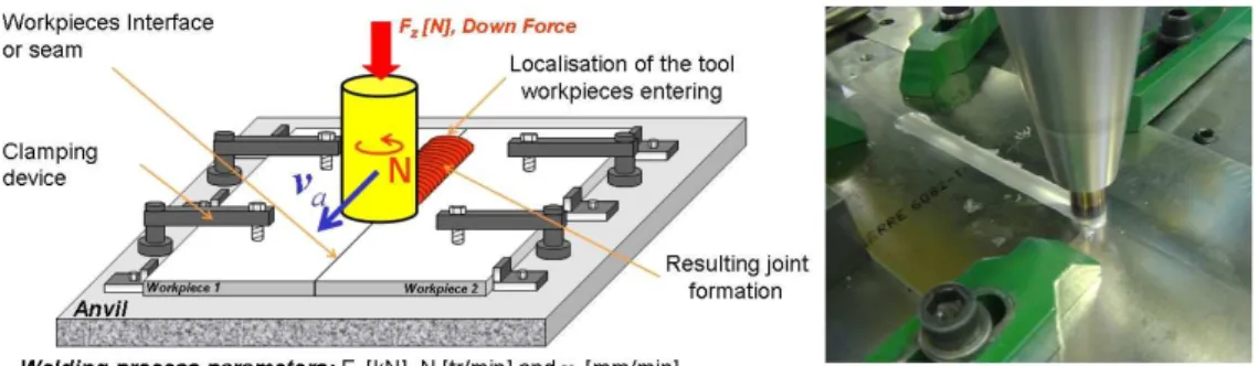
Friction Stir Welding (FSW) is an innovative welding process commonly known as being a solid state welding process [1]. This particularity gives it the availability to weld almost all types of aluminum alloys, even the one classified as non-weldable by fusion welding due to hot cracking and poor solidification microstructure in the fusion zone [2]. Furthermore, it meets the need from industrials to join similar or dissimilar aluminum parts together or with other metals like cupper or steel. This should be convincing arguments for industrials to use it. To perform FSW, a non-consumable rotating tool, made up of a shoulder and a pin, is inserted into the interface of two workpieces rigidly clamped to avoid any movement. Once the shoulder in contact with the surface’s workpieces, a constant down force is applied on the tool and is moved along the joint line, bounding the workpieces together. The Fig. 1 presents a schematic drawing and a picture of the FSW process.
Fig. 1 - Schematic drawing of Friction Stir Welding of two plates
The welding processing parameters, Fz, N and va are chosen in order to ensure the energy input and the tool kinematics in order to achieve a defect-less weld. In consequence, the FSW operation leads to the generation of a tool / workpiece mechanical interaction. So, during the whole welding process forces and torques are generated in the three directions. These process forces are generally described as being the most disadvantage of this welding process [3], because they are impacting the welding equipment requirements. Today, for most industrial applications, special dedicated machine were developed. These kinds of equipments, as not standard, are generally expensive. In consequence, the industrials are reluctant to adopt this new technology. So, if the production equipment cost could be reduced this technology will certainly widespread in terms of applications. Therefore, our research field is the industrialization of the friction stir welding, in order to provide tools to industrials to qualify a FSW welding equipment and the whole clamping
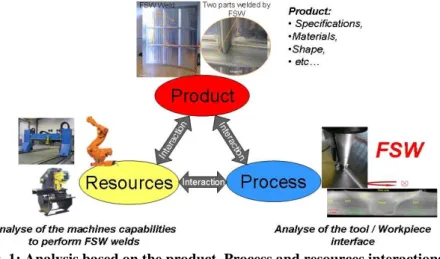
complex geometries, to offer a wide range of applications. To select and qualify a FSW equipment for a given application a methodology has been developed by Zimmer et al. [4]. It is based on the analysis of the interactions generated during welding between the product, the process and the resources. The Fig. 2 illustrates this approach. It leads to the determinations of the characteristics parameters to write down the technical requirements for the FSW equipment and the required clamping device.
Fig. 1: Analysis based on the product, Process and resources interactions
To achieve to this goal, Zimmer et al. [4] studied the interactions between the tool / workpiece interface and the tool / workpiece kinematics and mechanical interactions. The study of tool / workpiece kinematics and mechanical interactions is a local approach describing the local tool position and orientation, for each location of the welding path, according to the welding surface. It also defines the tool kinematics and the mechanical load applied on the tool to perform the operation. So, for each location of the welding path, the tool position and orientation is associated with the tool kinematics and the mechanical interactions applied on the tool. On the other hand, the analysis of the tool / workpiece interface interactions is a global approach leading to the determination of the whole positions and orientations of the tool during welding, according to the welding surface. Therefore, it defines the workspace required. This analysis has been preformed through a global investigation of the mechanical interaction generated during FSW. The tool / material mechanical interactions have been analyzed through the process forces and torque generated [4, 5]. This analysis permit to identify the two welding stages characteristic for the characterisation of a FSW equipment, namely the welding and the plunging stage. Therefore, these two welding stages should be investigated in order to analyze the influence of the processing parameters on the tool / workpiece mechanical interactions. All the analysis has been performed through experimental data collected during the welding with an instrumented FSW machine, the MTS I-STIR 10. In order to enable the use of a flexible and standard welding equipment, allowing the FSW of complex geometries, like an industrial the tool / workpiece mechanical interactions should be reduced. So, a method to achieve this goal is to work on the processing parameters. The Fig. 2 presents relationship between the input and output parameters in FSW with an emphasis on the load transmitted to the FSW welding equipment. Special attention will be paid to the influence of the FSW processing parameters on these parameters. The relationship between the processing parameters and the forces and torque generated were studied through a design of experiment experimental campaign for these two stages.
The results of these experimental campaigns will permit the characterisation of Friction Stir equipment. In this paper, we will present the result of the plunge experimental campaign and how these results can be used to characterize Friction Stir Spot Welding with an industrial robot.
Analysis of the plunge stage
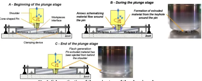
The plunge corresponds to the beginning of the welding operation; the tool has to be inserted into the joint line. The Fig. 3 presents a schematic view of the plunging sequence. At the beginning of the plunge, the tool is placed at the workpieces interface on the top surface. The two workpieces are rigidly clamped, near the plunge position, in order to avoid axial and transversal workpieces movements. After being placed into rotation, the tool is animated with a movement, in the rotation axis direction, with a velocity vp. Once, the parameterized plunging depth ∆z reached, the stage is finished. The tool shoulder is then, perfectly in contact with the workpieces’ top surface.
Fig. 3: Schematization of the main steps of the plunging phase
The processing parameters and the output parameters are given by the Fig. 4. It can be noted that the characteristic parameters for this stage, Fz and Cz are resulting from the material response of the applied processing parameters. If the FSW means of production has an axial force limit, depending on the processing parameters this limit could be reached. Therefore, it is important to choose processing parameters leading to acceptable axial force during the plunge in order to avoid damages to the means of production.
Plunging stage Velocity control mode Plunging stage Velocity control mode
Processing Parameters Process Output Parameters Fz max [kN] Fx, Fy[kN] Cz max [Nm] P [W] ∆∆∆∆tp[s] Fz max [kN] Fx, Fy[kN] Cz max [Nm] P [W] ∆∆∆∆tp[s] ∆∆∆∆z [mm] Np[tr/min] ap[mm/min²] dp[mm/min²] vp[mm/min] ∆∆∆∆z [mm] Np[tr/min] ap[mm/min²] dp[mm/min²] vp[mm/min]
Fig. 4: Processing and output parameters relationship during the plunge
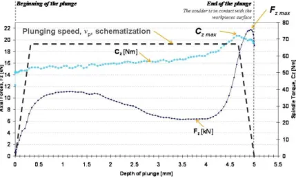
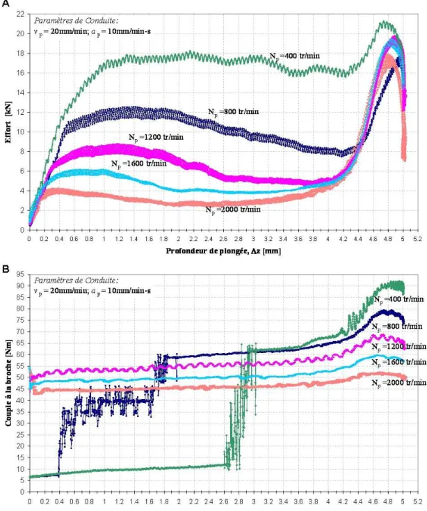
The Fig. 5 presents the characteristic curves of the axial force and spindle torque generated during the plunging operation. It represents the tool / workpiece mechanical interactions throughout the stage. The axial force Fz rises strongly during the first plunge millilitres, corresponding to the pin insertion into the cold material. Then, the pin is progressively inserted inside the workpieces leading to frictional and material plastic deformation heat generation, softening the material above the pin. Thus, the tool penetration is facilitated, leading to an axial force decrease. The insertion of the pin into the workpieces displaces approximately the pin volume material [7]. This leads to the formation of extruded material moving upwards the pin [6], Fig. 3-B. Then, the tool shoulder comes into contact with this extruded material, pushing it down to the workpieces surface. The squeezed material flows under the shoulder to form a continuous flash around
surface in contact involving a shear stress increase and consequently a torque increase. The forces and torque maximal intensities appeared generally at the end of the penetration, quite simultaneously. Therefore, for a static qualification of a FSW means of production, the maximal axial force and torque should be considered simultaneously for the calculation.
Fig. 5: Force and torque evolution according to the plunging depth Experimental procedure
Plunge experimental testing were performed in order to study the influence of the principal processing parameters, Fig. 2, the rotational speed Np and the plunging speed vp,, on the maximal axial force and torque, Fz max and Cz max. To proceed a variation of 33% and a 66% was applied on Np and vp according to the plunge processing parameters used during the welding operation. The tool acceleration / deceleration were calibrated in the same manner for each trial.
Results and discussion
The experimental investigation performed on this stage showed that the curve evolutions and maximal axial force and torque are depending on the process parameters. The Fig. 6 present the evolution of the axial force (Fig. 6-A) and the spindle torque evolution (Fig. 6-B) according to the spindle frequency while other processing parameters are constant. The axial force and torque are decreasing with increasing of the spindle frequency. This implies that the mechanical interactions between the tool and the workpiece are changing according to the processing parameters.
The torque evolution, and therefore the mechanical power (C x ω) dissipated into the workpiece during the plunge are depending on the processing parameters leading to different thermo-mechanical conditions. This heat input difference, from one trial to another, explains the different axial force evolution and the peak intensity difference.
Fig. 6: A, axial force, and B, torque, curves evolution depending on the processing parameters
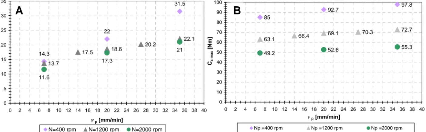
The Fig. 7 presents the maximal forces evolution according to the processing parameters. The lowest axial force appears when tool rotational frequency, N, is high and the plunging speed, vp, is low. The lowest spindle torque appears as N is the highest. Therefore, the analysis showed that the maximal forces and torque were both a functions of N and vp. Overall, two general tendencies can be identified. The first one is for a given Np, the values of Fz max and Cz max increases as vp increases. The second tendency is for a given vp, as Np increases, the maximal forces and torques decreases. This is due to the change of the generated thermo-mechanical interactions between the tool and the workpiece. The global analysis shows that Fz max is a function of Np and vp but is more sensitive to the evolutions of vp than Np. On the other side, Cz max is still a function Np and vp but is more sensitive to the evolutions of Np than vp. So, the lowest axial force and spindle torque occurred when the spindle frequency is the highest and the plunging speed is the lowest, i.e. when the heat input generated due to friction between the tool and the workpiece is the highest and the generated heat has time to be dissipated inside the workpiece by conduction, increasing the workpiece temperature in the
The analysis showed that the forces and torques generated during the plunging stage could be reduced by working on the processing parameters.
14.3 22 31.5 13.7 17.5 18.6 20.2 22.1 11.6 17.3 21 0 5 10 15 20 25 30 35 0 2 4 6 8 10 12 14 16 18 20 22 24 26 28 30 32 34 36 38 40 vp[mm/min] Fz m a x [ k N ] N=400 rpm N=1200 rpm N=2000 rpm 85 92.7 97.8 63.1 66.4 69.1 70.3 72.7 49.2 52.6 55.3 0 10 20 30 40 50 60 70 80 90 100 0 2 4 6 8 10 12 14 16 18 20 22 24 26 28 30 32 34 36 38 40 vp [mm/min] Cz m a x [ N m ] Np =400 rpm Np =1200 rpm Np =2000 rpm .
B
A
Fig. 7: A - Evolution of the maximal axial force according to the processing parameters, B- Evolution of the maximal spindle torque according to the processing parameters
Force and torque diagram according to the processing parameters
By drawing the maximal axial force and torque occurring during the plunging stage according to the couple of parameters Np and vp, an experimental plunging test experiment diagram can be dressed up, Fig. 7. Arbitrary force ranges are presented on the Fig. 8. As a FSW means of production is limited on axial force this force ranges can be used in order to select the appropriate sets of parameters to perform the applications on the means of production available, according to the force generated and to the stage productivity.
These results are interesting to select the appropriate sets of parameters to define the plunge stage or to perform Friction Stir Spot Welding.
0 200 400 600 800 1000 1200 1400 1600 1800 2000 0 2 4 6 8 10 12 14 16 18 20 22 24 26 28 30 32 34 36 38 40 42 44 46 48 Plunging speed, vp [mm/min]
R o ta ti o n a l F re q u e n c y , Np [ tr /m in ] (11.6kN ; 49.2Nm) (16.5kN ; 57.9Nm) (19kN ; 60Nm) (20.2kN ; 60.5Nm) (17.3kN ; 52.6Nm) (21kN ; 55.3Nm) (23.7kN ; 55.5Nm) (13.7kN ; 63.1Nm) (18.6kN ; 69.1Nm) (22.1kN ; 72.7Nm) (23.2kN ; 72.3Nm) (17.5kN ; 66.4Nm) (20.2kN ; 70.3Nm) (16.8kN ; 77.2Nm) (18kN ; 80.5Nm) (19kN ; 82.2Nm) (14.3kN ; 85Nm) (22kN ; 92.7Nm) (31.5kN ; 97.8Nm) (35kN ; 100Nm) (Fz max ; Cz max)
Fz max < 15kN 15kN ≤Fz max ≤25kN Fz max > 30 kN
Characterizing the FSW welding equipment, i.e. a serial kinematic robot
To characterize a FSW machine and workpieces work-holding device, it is necessary to verify that:
1. The tool can be placed in the position and orientation, according to seam, along the whole welding path, i.e. the trajectory can be followed. In the case of Friction Stir Spot Welding, it a one or a succession of position and orientation that is imposed. The notion of following a welding path is not required.
2. The machine can apply or withstand the force and torque generated by the tool on the welded material. It can be done, for a first approximation statically, by calculating the force and torque generated in each machine actuator and then verify if the load applied doesn’t exceed the one admissible.
3. The tool deviation occurring during the welding operation, generated due to machine lack of stiffness, is less than the one admissible. By using a machine stiffness model, it is possible to determine the tool deviation along the welding path and verify that the deviation is less than the one admissible.
By verifying these 4 points, the FSW machine is characterized from a static point of you. Using a serial kinematics robot to perform Friction Stir Spot Welding
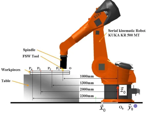
The two workpieces are placed in the robot workspace, on the welding table in front of him. They are clamped together (Fig. 9). The whole application, the robot, the welding head, the tool, the workpieces and the clamping device, is modelized in a software like DELMIA©. Thanks the software the tool accessibility, on the welding path or the welding points can be verified. Moreover, it is possible to obtain the position of the robot angular position. These data will permit to determine the required motor torque applied on each articulation motor. It is then possible to compare the one calculated with the one admissible for each motor.
Fig. 9: Friction Stir Points Welding with a serial kinematics robot
As presented on the Fig. 9, the Friction Stir Spot Welding operation is composed of 4 points workpiece The welding points are at 1000mm (P1), 1300mm (P2), 2000mm (P3) and 2300mm (P4) above the base of the robot. With the diagram on Fig. 8 we select the processing parameters permitting to realize the operation
capacities. The maximal axial force allowed by the welding head is 14kN and the maximal torque is 60Nm. So, the only experimental point satisfying these two criteria is for the following processing parameters: the plunging vp =7mm/min and Np = 2000tr/min. For these experimental points, the maximal axial force generated is 11.6kN and the spindle torque is 49.2Nm. By calculating the required motor torque at each robot articulation, for each of the four points, it appears that for the points at P3 and P4, the torque generated at some articulation is greater than the one admissible. This means that, if the operation is performed, the robot safety system will stop the application due to current overflow. Therefore, the welding application positioned and oriented in this configuration inside the workspace doesn’t allow the welding feasibility. So, with a serial kinematics robot, the welding capacities will depend on:
- the processing parameters chosen and the generated process forces and torque - the position and orientation of the tool inside the workspace.
Therefore, the welding capacities of a serial kinematics robot can not be directly be drawn inside the process windows.
Conclusion and future work
To qualify a FSW equipment experimental investigations have been performed on the welding at constant speed stage and the plunging stage. It permits to evaluate the tool / material interactions through the process forces and torque generation according to the processing parameters, for one material, thickness and tool geometry. The experimental results permit to establish diagrams presenting the axial force according to the processing for the two stages characteristics for a FSW equipment static qualification. These diagrams permit to select the process windows ranges allowing the FSW with the available mean of production. To complete these work, another dimension should be added to this diagram, the weld mechanical properties in order to select the processing according to the weld quality and the available FSW equipment.
Acknowledgement
The authors would like to thanks the Region Lorraine, the Moselle department and the french Government to finance this research project and Daniel Strina for its technical support.
References
[1] W.M. Thomas, E.D. Nicholas, J.C. Needham, M.G. Murch, P. Templemith, C.J. Dawes (1991). Patent Application No. 9125978.8
[2] R.S Mishra, Z.Y. Ma, Friction Stir Welding and processing, Materials Sciences and Engineering R 50 (2005) I-78
[3] W. J. Arbegast, Application of Friction Stir Welding and related technologies. Friction Stir Welding and Processing ISBN: 978-0-87170-840-3, Chapter 13 p.274
[4] S. Zimmer, L. Langlois, J. Laye, J.-C. Goussain, P. Martin, R. Bigot, Methodology for qualifying a Friction Stir Welding equipment, Proceedings of the 7th International Symposium on Friction Stir Welding 2008
[ 5] S. Zimmer, L. Langlois, J. Laye, J.-C. Goussain, P. Martin, R. Bigot, 2009, Using the plunging and welding process windows to determine a FSW means of production, THERMEC 2009 Berlin
[6] A. Gerlich, P. Su, T. H. North Tool penetration during friction stir spot welding of Al and Mg alloys Journal of Materials Science, 2005, pp6473-6481
[7] M. F. Zaeh, D. Eireiner, L. Papadakis Friction Stir Welding with modern milling machines. Requirements, Approach and Application Proceedings of the 5th International Symposium on Friction Stir Welding - France, September 2004