UNIVERSITÉ DU QUÉBEC À
MONTRÉAL
CMMN MODELS HAND-DRA WN SKETCHES RECOGNITION SYSTEM
MASTER THESIS
PRESENTED
AS A PARTIAL REQUIREMENT
FOR THE MASTER IN COMPUTER SCIENCE
BY
SARA AMIRSARDARI
UNIVERSITÉ DU QUÉBEC À MONTRÉAL
Service des bibliothèques
Avertissement
La diffusion de ce mémoire se fait dans le respect des droits de son auteur, qui a signé
le formulaire
Autorisation de reproduire et de diffuser un travail de recherche de cycles
supérieurs (SDU-522 - Rév.07-2011 ).
Cette autorisation stipule que
«conformément à
l'article 11 du Règlement no 8 des études de cycles supérieurs
, (l'auteur] concède à
l'Université du Québec à Montréal une licence non exclusive d'utilisation et de
publication de la totalité ou d'une partie importante de [son] travail de recherche pour
des fins pédagogiques et non commerciales.
Plus précisément,
[l'auteur] autorise
l'Université du Québec à
Montréal
à
reproduire
, diffuser, prêter, distribuer ou vendre des
copies de [son] travail de recherche
à
des fins non commerciales sur quelque support
que ce soit, y compris l'Internet. Cette licence et cette autor
isation n'entraînent pas une
renonciation de [la] part [de l'auteur] à [ses] droits moraux ni à [ses] droits de propriété
intellectuelle. Sauf entente contraire
,
(l
'auteur] conserve la liberté de diffuser et de
commercialiser ou non ce travail dont [il] possède un exemplaire.»
UNIVERSITÉ DU QUÉBEC À
MONTRÉAL
UN SYSTÈME DE RECONNAISSANCE DES ESQUISSES
DE MODÈLES
CMMN DESSINÉS À
LA MAIN
MÉMOIRE
PRÉSENTÉ
COMME EXIGENCE PARTIELLE
DE LA MAÎTRISE EN INFORMATIQUE
PAR
SARA AMIRSARDARI
ACKNOWLEDGMENTS
lt gives
me
great
pleasure in
expressing
my
gratitude to all
those people
who
have
supported
me and
had their contributions in making this thesis possible.
First and foremost,
I
would
like to thank
my advisor
,
Professor
Hafedh
Mil
i
,
for
hi
s
constant g
uid
ance
,
support
,
motivation, inspiration
,
enthusiasm
,
and
immen
se
knowledge.
1
would also
like to
acknowledge Renata Carvalho
,
as the
second
reader of
this thes
is
,
and I am gratefu
ll
y
indebted to her for her very valuable comments on this thesis.
l
am
indebted
to
my friends
and co
ll
eagues for
providing
a stimulat
ing environment
in
which
I
cou
ld
learn
and grow
,
especiall
y
I thank my
fr
iends
,
Imen
,
Anis
,
Amani
and Golrokh
.
l
would
like to thank a
il
the staff members
of the
Computer Science
department
at
UQAM for their direct a
nd
indirect helps during my studies at UQAM.
Last but not
least
,
I
wo
uld like
to
express
my
very profound
gratitude to
my parents
,
Mohammad and Akram
,
and to
Marco
for
providing me
with
unfailing
support for
their
love,
encouragement
,
advice
throughout my
years of study and
through
the
process
of researching
and writing
this thesis.
This accomplishment would
not have
been possible without them. Thank you.
TABLE OF CONTENTS
LIST OF FIGURES
...
.
...
...
.
..
.
...
i
x
LIST OF TABLES
...
.
..
.
.
...
...
...
.
....
...
.
...
...
... x
iii
RÉSUMÉ
.
...
.
.
.
.
...
.
...
.
...
....
.
...
.
...
.
...
...
...
...
.
.
..
..
..
...
XVABSTRACT ...
....
...
...
...
..
...
.
...
...
...
...
...
...
..
...
...
...
...
...
... xvii
INTRODUCTION
...
.
...
....
.
...
...
...
...
. 1
0.1
Problem
Statement ...
.
...
.
.
....
.
.
....
...
2
0.2
Objective
..
..
.
...
....
...
.
.
...
.
...
.
...
.
..
.
...
...
...
..
...
...
... 4
0.3
Methodology
...
.
...
.
...
4
0.4
Thesis Plan ...
...
.
...
....
..
...
... 5
CHAPTERl
STATE OF THE ART ON SKETCH RECOGNCTlON SYSTEMS ...
...
...
.... 7
1.1
Vector Graph
ies and Raster Graphi
es
...
...
...
.
...
...
... 8
1.2
Optical Character Recogn
itio
n ...
.
..
....
...
.
...
.
...
....
...
9
1.2.l Offline Recognition ...
...
....
...
..
... 10
1.2.2 On
li
ne Recognit
ion ...
...
.
...
....
.
.
...
.
...
..
... 1
3
1.3
Sketch Recognition Systems
....
..
...
.
...
...
..
...
...
.
..
...
...
23
1.
3.1
Sketch-Based Tools for
UML Class
Diagrams
...
.
...
...
..
...
25
1.3.2 Sketch-Based
Tools
in Other Domains
...
.
...
.
.
...
...
28
1.4
Conc
lusion
...
...
...
...
..
.
...
..
..
...
...
.
...
.
...
..
... 31
CHAPITRE
Il
CASE MANAGEMENT MOD
EL
AND NOTATION (CMMN)
....
....
...
...
...
... 33
2.1
Notations
..
.
...
.
...
...
..
..
...
....
...
34
2.1.1 Case
...
.
...
...
...
...
...
34
2.
1.
2
Case P
lan Madel.
...
...
.
....
.
...
34
VI
2.1.4 Stage
.
...
...
.
.
....
...
...
.
...
.
.
.
.
...
..
...
...
...
...
...
... 37
2.1.5
Eve
nt
.
..
...
.
..
.
...
.
...
...
...
..
..
..
.
...
.
....
.
.
..
...
...
38
2.1.6
Case
File .
..
.
.
.
....
..
...
...
...
...
...
..
...
...
..
.
..
...
...
...
. 38
2.1.7 Mi
l
es
ton
e
Item ..
.
..
...
..
...
.
.
.
....
...
..
.
.
...
.
.
.
.
..
.
.
.
...
...
... 39
2.1.8 Sentry
..
...
.
.
..
...
.
..
.
.
...
..
....
...
.
...
...
..
...
...
...
.
.
..
.
....
...
39
2.
1.9 Connector
...
.
...
.
...
...
...
.
...
...
..
..
.
.
.
..
..
.
..
..
.
...
.
...
.
...
40
2.2
Exa
mpl
e of Case
Plan Model
...
.
...
...
...
.
.
...
.
....
..
...
...
...
..
.
...
... .43
2.
3
Conc
lus
i
o
n ..
..
....
.
....
.
.
...
...
.
...
...
..
...
...
..
.
...
...
.
...
...
..
...
....
44
C
HAPITRE
lII
EX
P
E
RJM
ENTAL
RESULTS
...
...
.
....
...
...
..
.
...
...
... .45
3.1
Case Study
...
..
...
.
...
.
...
.
.
..
...
...
....
...
.
...
..
....
.
.
....
...
..
....
45
3.2
Techno
logy
Use
d .
...
.
...
.
...
.
.
...
..
...
...
..
.
..
..
.
..
.
.
47
3.3
Sketc
h Reco
g
niti
on D
es
i
g
n and
lmplementation ..
...
...
...
..
..
..
...
.. .48
3.4
Primitive Shape Reco
g
nition ...
.
...
....
.
...
...
...
.
....
...
..
...
...
..
...
.49
3.4.
1 R
ea
din
g
Hand-Drawn Sketch .
...
...
..
.
.
..
...
...
..
...
...
...
..
....
.
.
..
..
...
.
..
.. .49
3.4.2
Pre-Proces
s
in
g
...
.
.
....
.
.
....
....
...
...
....
...
.
.
.
...
.
....
.
. 50
3.4.3
Co
ntour
F
indin
g
...
.
...
..
...
..
.
...
...
....
...
.
....
....
....
....
54
3.4.4
Fea
ture
Ex
traction ...
..
.
..
..
.
...
...
...
.
.
.
...
.
...
....
...
...
59
3.4.5 Conto
ur Resi
z
ing
.
...
..
.
....
....
...
..
...
...
.
..
...
.
.
.
.
.
.
.
.
.
...
.
...
..
60
3.4.6 Te1nplate Matchin
g
...
...
...
...
...
..
...
.
..
.
..
...
...
.
...
...
.
...
6
1
3.4.7 Co
nto
ur Di
s
tance ..
...
...
..
...
...
...
.
...
.
...
..
..
...
..
.
68
3.4.8 L
ine
Detection ...
...
..
.
.
...
...
..
....
.
...
...
.
...
... 68
3.4.
9 L
ine
Di
stance ....
.
.
...
..
.
..
..
...
...
..
...
....
..
...
72
3.5
Co
mpos
ite Graphi
e Obj
ec
t Recognition .
..
...
..
.
.
.
..
...
..
... 72
3
.5
.1 Intersection Area ...
...
..
...
....
73
3.5.2 Con
nector Detection ...
..
...
..
.
...
..
.
...
.
...
...
...
.
..
.... 74
3.6
Se
mantic Con
nection Recognition
and
Understanding
...
...
...
.
...
.
.
.
...
.
76
3.6.
1
Case
...
...
...
.
...
...
.
..
..
...
.
..
...
..
...
...
.
....
.
...
..
...
.
..
..
.
...
.
...
.
... 77
3.6.2 CMMN
or ...
.
.
.
..
...
...
..
...
.
.
.
.
.
.
...
...
..
...
.
..
.
...
82
VII
CHAPITRE IV
TEST SETTING AND RESULTS
...
...
....
...
.
...
.
...
.
....
.
...
85
4.1
Test Setting Overview
..
.
....
...
..
....
.
....
...
...
.
..
...
...
...
..
...
..
..
..
...
.. 86
4.2
Recognition
Acc
uracy
....
...
...
...
.
...
..
..
...
...
.
....
..
....
...
...
87
4.3
Limitations ...
...
...
...
...
..
...
.
...
.
..
...
....
.
..
...
.
..
90
CONCLUS
ION
...
..
..
.
.
.
.
..
...
.
.
..
.
.
..
.
....
..
....
.
.
...
.
.
.
.
.
..
...
.
...
....
....
...
...
... 93
APPEND[CEA
PRIMITIV
E
SHAPE RECOGNITION JAVA CLASSES
...
.
...
...
...
..
....
.
.
..
....
97
A
PP
END
I
CE
B
COM
POSIT
E
SHAPE RECOGNITION JAVA CLASSES ... 12
3
APPENDICE
C
SEMANTIC CONNECTION RECOGNITION JAVA CLASSES ...
...
.
..
. 139
BIBLIOGRAPHY .
...
...
...
...
...
..
... 16
3
LIST OF FIGURES
Figure
P
age
Fi
g
ure
1
.
1 Represents vector and
raster graphies
.
...
..
..
...
..
...
...
...
... 8
F
igure
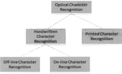
1.2 Class
ification of optical character recognition
..
..
...
....
.
...
..
10
Fi
g
ure 1.
3
Offline recognition ...
.
.
...
.
..
..
.
...
..
...
..
...
.
.
..
..
.
.
...
...
.
.
...
.
.
..
...
.... 11
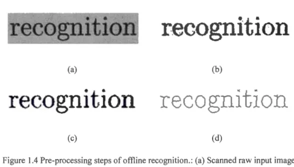
Figure
1.4 Pre-processing
s
teps of offli
ne recognition
..
....
.
...
.
...
...
...
...
...
12
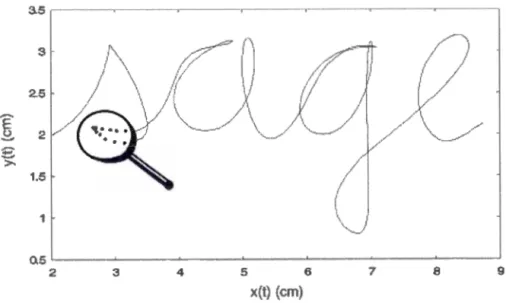
Figure
1
.
5 Online recognition ....
...
..
...
...
....
...
.
..
.
.
..
...
...
..
... 14
Figur
e
1.6 Primitive shape recognition ste
ps ...
....
....
...
..
..
... 14
Figure
1.7
Subprocesses of
o
nline
gra
phie
s
recognition ..
....
..
.
...
...
... 15
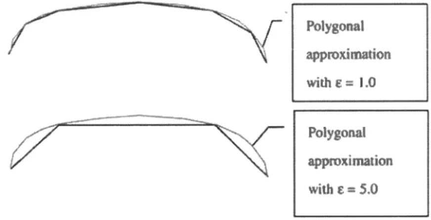
Figure
1
.
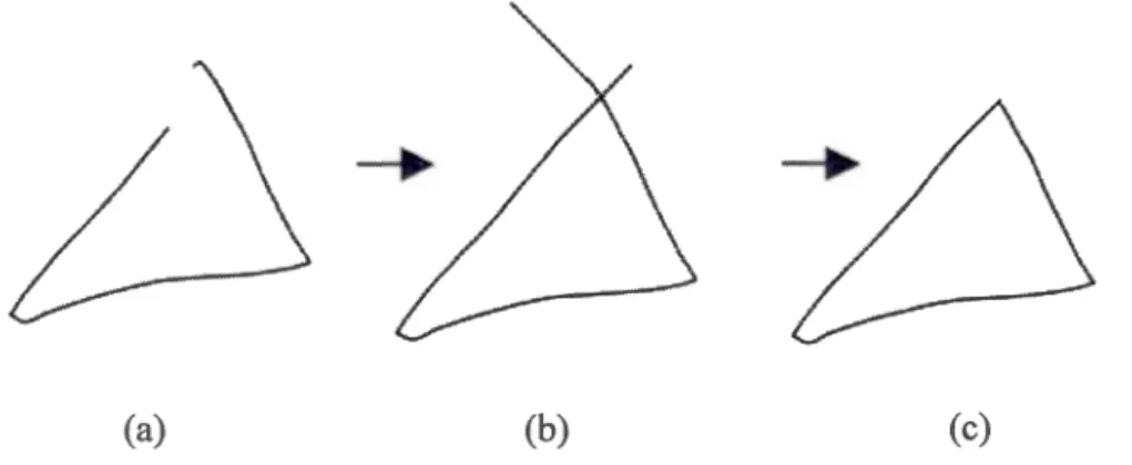
8 Illustrations of the poly
go
nal
ap
proximation proce
ss
.
.
.
.
...
..
... 16
Figure
1.9
A
gg
lomerate po
ints
...
...
...
...
...
...
...
...
...
.
...
...
... 17
Figure
1.10 Agglomerate points filtering
...
..
....
..
.
.
...
.
...
...
.
...
...
..
17
Figure
1.11
Shapes w
ith
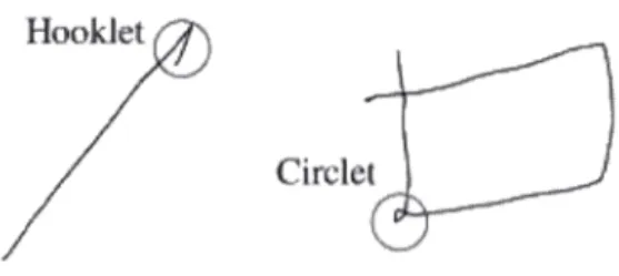
improper endpoints ...
....
...
.
...
.
.
...
...
..
...
..
..
. 18
Figure
1.12
Exa
mples of end
point refinement ...
..
...
...
...
...
18
Figure
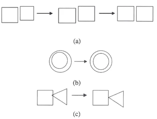
1.13 Inner shape regularization
...
..
...
...
...
...
.
....
...
... 22
Figure
1.14 Inter-shape regularization ...
...
.
...
.
...
...
..
...
..
.
... 23
Figure
1
.
15
LAD
DER Framework
.
..
.
...
...
...
...
..
...
...
..
...
..
..
...
..
... 27
F
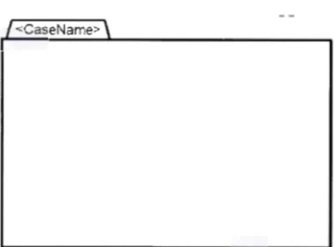
igure 2.1
Represents Case Plan Mode!
shape ...
...
...
.
35
Figure 2.2 Ordinary Task shape
and Discretionary Task
s
hape
...
...
...
... 35
Fi
g
ure 2.3 Non-Blocking Human Task shapes
...
.
....
..
...
.
....
...
...
... 36
Figure 2.4 Blocking H
uman Task s
hapes
...
.
.
.
..
.
.
.
....
.
....
...
..
...
.. 36
Figure 2.5
Proces
s
Task
s
hapes
....
...
..
...
.
...
..
...
.
.
.
...
.
.
...
.
.
....
.
....
..
...
..
...
... 36
X
Figure
2.
7 Case Task shapes ...
...
..
....
...
3
7
Figure
2.8
Expanded Stage shape and Co
ll
apsed Stage shape ....
...
...
..
38
Figu
re
2
.
9
Eve
nt shapes ...
...
...
...
...
38
Figure
2.10
Case F
il
e shape
...
39
Figure
2.1
1
Mi
lestone shape
...
...
...
39
Figure
2.
1
2
Entry Criterion shape a
nd
Exit Criterion shape ... .40
Figure
2.13
Conn
ector Shape ...
40
F
igure
2.14
Sentry based depend
ency between two tasks ...
...
.40
F
igure 2.15 Using sentry-based co
nnectors to
visua
lize
"AND" ...
...
...
.41
F
igure
2
.1
6
Usi
ng se
ntry-based connectors to visualize "OR" ...
.41
Figure
2.17
Yisualize dependency between stages ...
..
...
...
..
....
...
42
Figure
2
.18
vis
ual
ize dependency between a task and a
milestone
...
....
....
....
42
Figure
2.
1
9
Yisualize dependency between a Task and
a Ti
mer Event Listener ...
42
F
igure
2.20
Yisualize depende
nc
y between a task and a case file
item ...
43
Figure 2.21
combinat
ions of various e
lements
in
CMMN ...
..
...
44
Figure
3.
1
Formalizes case mode! from
a CMMN hand-drawn sketch ...
46
Figure
3.2
OpenCV library on the Eclipse IDE
...
...
...
...
..
47
Figure 3.3
Represents the data structure in
OpenCV ... .48
Figure
3.4
Design mode!
compatibl
e with
the case study ...
..
...
49
Figure
3.5
Templates
images ...
...
..
....
..
...
.
50
Figure
3.6
Pre-processing steps of
the recognition system
...
...
....
51
F
igure
3.7
Gaussian blur on
10 pixel array ...
..
...
52
Figure
3.8
1 D Gaussian kernel ...
..
...
53
Figure
3.9
T
hres
hold
operat
ion
...
..
...
....
..
...
...
54
Figure
3.
10 Show graphicall
y a pixe
l image and the correspondin
g co
ntour ... 55
XI