HAL Id: hal-00564956
https://hal.archives-ouvertes.fr/hal-00564956
Submitted on 10 Feb 2011
HAL is a multi-disciplinary open access
archive for the deposit and dissemination of
sci-entific research documents, whether they are
pub-L’archive ouverte pluridisciplinaire HAL, est
destinée au dépôt et à la diffusion de documents
scientifiques de niveau recherche, publiés ou non,
To cite this version:
Eric Bonjour, Ghassen Harmel, Jean-Pierre Micaëlli, Maryvonne Dulmet. Simulating change
propaga-tion between product architecture and development organizapropaga-tion.. Internapropaga-tional Journal of Mass
Cus-tomisation, Inderscience, 2010, 3 (3), pp.288-310. �10.1504/IJMASSC.2010.036800�. �hal-00564956�
Simulating change propagation between product
architecture and development organization
Eric Bonjour
1*, Ghassen Harmel
1,
Jean-Pierre Micaëlli
2, Maryvonne Dulmet
11
FEMTO-ST Institute, UMR CNRS 6174 - UFC / ENSMM / UTBM, Automatic Control and Micro-Mechatronic Systems Department, 24, rue Alain Savary, 25000 Besançon, France – Phone: +33 3 81 40 27 98 – Fax: +33 3 81 40 28 09 –
[email protected] - [email protected]
2
RECITS laboratory, University of Technology of Belfort-Montbéliard, 90010 Belfort Cedex, France –
[email protected] *Corresponding author
Abstract: In order to limit the effects of technological change on product design, concepts like product architecture and modularity have been introduced, in order to support complex product development. In engineering design, numerous works have studied this central issue but change propagation within product architecture has been hardly addressed. Concerning organizational issues, many researchers in the field of industrial engineering have paid careful attention to new organization design but hardly to an incremental evolution of project organization. Galbraith (1977) highlighted that product architecture and development organization were strongly interrelated. However, little research has studied this relationship, and the need for a coherent model of product and organization co-evolution remains. This paper aims at presenting a matrix-based method that should help design managers to simulate change propagation between product architecture and development organization. This method uses a "management by uncertainty" approach and a mathematical model in order to propagate change. An industrial case study illustrates it in case of component changes.
Keywords: change propagation, design, DSM, organization structure, team, product architecture, uncertainty management.
1 Introduction
It has been widely observed that the development of new products has become a “critical weapon” for firms acting in competitive environment. More demanding customers and regulations, but also opportunities in innovative technologies are some of the factors that force firms to become innovative. Complex Systems Engineering is facing continuous technological evolution that involves new generations of product and changes in both functional teams' skills and their interactions within the development project. In this context, Henderson and Clark (1990) conducted in the early 1990s a study focused on the coupling of product architecture and organization structure. They introduced a framework to study the effects of product architecture innovation in established firms'
development organizations. They suggested that architectural innovation threatens established firms not only because they are slow in recognizing novel architectures, but also because their development organizations elaborate architectural knowledge specific to the established product architecture.
Not surprisingly, researchers got more and more interested in modelling product development projects situations and explored the needs for concurrently designing product architecture, development organization and processes (Eppinger and Salminen, 2001; Meinadier, 2002). Other researchers focused on the product architecture and the organization (Oosterman, 2001). Sanchez and Mahoney (1996) discussed the notion of modular organization to hypothesize that standardized design interfaces between components in a product design provide a “means to embed coordination of loosely coupled components development processes”. Sosa (Sosa et al., 2003) studied the coupling of product architecture and organization structure in complex product development, and focused more specially on understanding the effects of product architecture on technical communication between several organizations implied in product development. The general approach when developing complex products is to decompose the product into systems, and if the systems are still too complex, to decompose these into smaller components (Alexander, 1964; Pimmler and Eppinger, 1994; Eppinger, 1997). This way of organizing the designed product and its design process proved its efficiency in automotive industry, especially in the case of powertrains development, as described in this article. This type of system involves the design of both modular and integrative sub-systems.
This paper aims at presenting a method to help managers propagate changes and manage the co-evolution of product architecture and design project organization structure in situation of uncertainties threat, early in the system definition stage. First, we begin with a concise literature review. Second, we present an architecture typology and the matrix-based models (DSM and incidence matrix that provide powerful representations of systems architecture). The proposed method is then detailed and applied to the development situation of a new gearbox that shifts from manual to robotized technology and implies component changes. This method relies on matrix-based models and a "management by uncertainty" approach for modelling bi-directional change propagation between product architecture and organization structure (that is what we call co-evolution). Finally, a brief discussion and further research are formulated.
2 Literature Overview
Eppinger and Salminen (2001) distinguish three domains that make up a design project: product, process and organization. The product domain is usually split up into different sub-domains: functions, physical components, parameters. In this paper, we only focus on product and organization domains. Thus, the literature overview presented in this part is intentionally limited to design engineering researches dealing with architecture modelling. Moreover, the method proposed in this paper mainly links three research fields: (1) product architecture, (2) organization structure, and (3) engineering change propagation. Figure 1 shows that the overlapping of these research fields defines four deeper research domains (4; 5; 6; 7). Some related works are as follows:
1. Product architecture only: those related to modular product design (Dahmus et al., 2001; Whitfield et al., 2002; Yu et al., 2003; Sharman and Yassine, 2004, Hölttä-Otto, 2005; Jiao et al., 2006) and those related to interface modelling (Van Wie, 2001);
2. Organization structure only: those dealing with organization decomposition into design teams (David et al., 2002; Tseng et al., 2004; Fitzpatrick and Askin, 2005) and those dealing with design tasks structure (Eppinger et al., 1994; Chen and Lin, 2003); 3. Engineering change propagation and uncertainty management only: engineering change management (Lindemann, 1998), project risk management (Herroelen and Leus, 2005; Chapman and Ward, 2002) and decision making (Erdem and Keane, 1996);
4. Product architecture and organization structure (McCord and Eppinger, 1993; Sanchez and Mahoney, 1996; Browning, 2001; Eppinger et Salminen, 2001; Cho, 2001; Oosterman, 2001; Sosa et al., 2003; Danilovic and Browning, 2007; Robin el al., 2007); 5. Product architecture evolution modelling (Balachandra, 2002; Clarkson et al., 2004; Chen and Liu, 2005; Keller et al., 2005; Avak, 2006);
6. Organization structure evolution modelling: (Galbraith, 1977), (Galbraith, 1994); 7. Product architecture and organization structure co-evolution: no research found.
Figure 1 Related literature on propagating change between product architecture and organization
Engineering change propagation
Product architecture 1 2Organization structure
3 5
4 6
7
We consider that the terms "architecture" and "structure" are synonyms but we will mainly use the conventional terms "product architecture" and "organization structure". Through the literature overview presented above, we notice that even though product architecture and organization structure co-evolution research domain is at the intersection of three important research domains, no major work was found.
3 From Product Architecture to Organization Structure
In the engineering design field, architecture terminology is often linked to the product. Ulrich (1995) defines product architectures as “the scheme by which the function of a product is allocated to physical components.” A key feature of product architecture is the degree to which it is modular or integral. In modular architectures, functions of the product map one-to-one to its physical components. At the other extreme, in integral architectures a large subset of product functions map to a single or small number of components. In real design situations, designers have to make a trade-off between modular and integral architectures. Hence, many products are hybrid (Sosa et al. 2000). Their architectures are not fully modular or integral and lie somewhere between the two extremes.
Generally speaking, the notion of architecture is also used for all systems that may be decomposed into smaller inter-related sub-systems, from a functional view and a physical view (IEEE Std 1220™, 2005). Development organization can be considered as a social system that aims at developing a product (Meinadier, 2002). The functional view of the organization corresponds to the development process that specifies the goals the design teams have to achieve. The physical view of the organization corresponds to all design teams that make up the project team and that may be decomposed into smaller groups and
individual designers. In complex product development projects, many teams develop the components, or systems, and other are responsible for the integration all of these components in the final product. Yassine and Braha (2003) call these teams "local development teams" (in charge of sub-systems development) and system teams (product integrators). Previous typologies and works implicitly assume that the most efficient organization structure in case of complex systems development project corresponds to a matching between systems/sub-systems and teams.
To be more general, we define a modular team as a team whose team members have a lot of information exchanges between one another and that have no (or few) interactions with other design teams. We define an integrative designer (or design team) as a designer who needs to interact with many other designers or modular teams.
4 Matrix-based Models
Although other product architecture representations have been used in engineering literature, for instance, diagrams (Stone et al., 2000) or oriented graphs (Kusiak and Huang, 1996), matrix-based models are the most conventional representations and have the great advantage to provide a common modelling tool both for product architecture and organization structure. A matrix-based system architecture model represents the system structure (list of its elements and their relationships) as a matrix. In this part, according to Malmqvist's classification (2002), we briefly present two types of matrix that prove invaluable in modelling project domains and their relationships: intra-domain matrix (or DSM), and inter-domains matrix (or incidence matrix).
4.1
Intra-domain Matrix or Design Structure Matrix
Intra-domain matrices represent relationships between elements of the same domain in a compact and visual format. These matrices are usually called DSM: Design (or Dependency) Structure Matrix (Steward and Donald, 1981). DSM are becoming popular modelling and analysis tools, especially for purposes of decomposition and integration. DSM are square matrices with identical elements in rows and columns. Elements may be product components, design tasks, design parameters or design teams. Cells along the diagonal have no sense. Reading across a row reveals what other elements the element in that row provides. Scanning down a column reveals what other elements the element in that column depends on. The use of DSM in both research and industrial applications has greatly increased since 1990s. DSM have been successfully applied in various fields, for instance: automotive (Pimmler and Eppinger, 1994; Browning, 2001), aerospace (Sosa, 2000, 2003; Sharman and Yassine, 2004) and electronics (Carrascosa et al., 1998).
Browning (2001) reviews four types of DSM that split up into two static DSM (component-based or architecture DSM; team-based or organization DSM) and two time-based DSM (Activity-time-based or schedule DSM; parameter-time-based or low-level schedule DSM). Static DSM are optimized with clustering algorithms while time-based DSM are resequenced with partitioning algorithms. In the product domain, the taxonomy proposed by Pimmler and Eppinger (1994) identifies four types of interactions within a product: spatial-, energy-, information- and material interactions. They link these interactions with the necessary design efforts to integrate the product. Oosterman (2001) has enriched this typology to better match interactions within the product architecture with the need for coordination within the project organization. In the purpose of establishing product architecture, DSM are used to analyze interactions, determine clusters (or modules) and
define appropriate interfaces in each product sub-domain (Yu et al., 2003; Van Wie et al., 2001; Chen and Liu, 2005; Fixson 2005). During a redesign process a change to one component of the product will, in most cases, result in changes to other components. An interesting approach for predicting and visualizing change propagation has been proposed in (Clarkson et al. 2004) and (Keller et al. 2005). The authors develop DSM representations and mathematical models to predict the risk of change propagation in terms of likelihood and impact of change.
In the field of project organization, DSM applications concern either the scheduling of design tasks and the identification of iteration in design (Eppinger et al. 1994; Browning, 2001; Whitfield et al. 2005) or the decomposition and integration of large design projects into different teams (Mc Cord and Eppinger, 1993; Sosa et al., 2003). Particularly, Chen and Lin (2003) propose a method to decompose a large interdependent task group into smaller and manageable sub-groups. The authors use DSM, analytic hierarchy process and cluster analysis to represent task relationships, quantify task couplings and decompose large size of task groups. Chen (2005) develops a methodological framework for project task coordination and team organization, in order to assign the right team members to the right tasks.
4.2
Inter-domains matrix or incidence matrix
Inter-domains matrices represent relationships between two domains. These matrices are basically incidence matrices. They are also called traceability and allocation matrices (IEEE Std 1220™, 2005; Fixson 2005), incidence matrices (Chen and Liu, 2005) or Domain Mapping Matrices (DMM) (Lindemann, 2007; Danilovic and Browning, 2007). They can represent a set of design decisions or relationships between "what" and "how". Some authors use other names such as axiomatic design matrix (Suh 1990). Indeed, Axiomatic Design (AD) pays considerable attention to the relationships between Functional Requirements (FR) and physical Design Parameters (DP). The former (FR) correspond to elements in the functional domain and describe design goals. The latter (DP) correspond to elements in the physical domain and aim at satisfying particular FR. DP are means ("how") to fulfil the FR ("what"). According to AD, the decomposition of a design problem follows a "zigzagging" top-down approach between the hierarchies of the functional and physical domains. The Axiomatic design matrix (A) indicates how the DP together address the FR at each level of the hierarchy. The following equation is used: {FR}=[A]{DP}. The matrix A may be uncoupled, decoupled or coupled.
Ulrich (1995) defines product architectures as “the scheme by which the function of a product is allocated to physical components.” Fixson (2005) proposes to create a "Function-component allocation" matrix. In the cells of this matrix, "percentages of a function can be allocated to components that contribute to this function". In the field of project organization, there is still limited research that provides analytical solutions for team formation. Particularly, incidence matrices have rarely been used. The most interesting research work concerns a methodology for the multi-functional teams’ formation (Tseng et al., 2004). The authors use an incidence matrix to represent relationships between customer requirements and project characteristics. They adapt a rank order clustering algorithm for grouping these characteristics based on customer requirements. Following this step, desired team members for each team are then selected.
Whereas a number of research studies have used DSM as an architecture representation, inter-domains matrix-based methods in project development context are
rare. We assume in our research work that incidence matrices are of high importance because:
1. They may ensure the cohesion between project domains (Product, process, and Organization) and particularly, between the product sub-domains;
2. They capture the mapping of one domain onto another and particularly, correspond to the system architects' key competence: mapping from functions onto components.
The method presented in this paper combines DSM and incidence matrices as representation and propagation tools of project domains architecture. We assume that one team is responsible for the fulfilment of one design task, and we limit our study to the relationships between the product architecture and the organization structure. Furthermore, as mentioned above, their matrix representation corresponds to static DSM and then, the optimization algorithm is the same: a clustering algorithm.
5 A New Method to propagate Change
Sosa et al. (2003) present a research method that provides a useful approach to investigate the coupling of the product architecture and the development organization. It can be summarized in three steps:
- Capture the product architecture by documenting design interfaces, - Capture the development organization by documenting team interactions,
- Couple the product architecture with the development organization by comparing design interfaces with team interactions.
The first two steps of our method are similar to this paper. We sum up a new method to propagate change from product architecture to organization in six steps:
1. Capture the initial product architecture (Initial DSMP). We first identify how the product is decomposed into components. We then document the design interfaces between them. Lastly, we analyze the distribution of cross-systems design interfaces to identify modular and integrative systems,
2. Capture the initial development organization (Initial DSMO). We first identify the designers responsible for the development of product components. We then survey designers to capture the technical interactions between them,
3. Capture the initial incidence matrix. We identify the assignment relationships between product components and the development organization teams (or members). We use the lists identified in the product architecture and the development organization,
4. Verify the alignment of product architecture and organization structure. Since our purpose is to propagate change and to ensure the co-evolution of these two project domains, it is important to verify that initial project domains architectures are coherent,
5. Introduce changes in the initial development project situation. System architects and designers have to predict and introduce one or several modifications in the project domains. We propose a typology of uncertainties to model these modifications. Our method guides the system architects to manually propagate the change by exploring uncertainties and obtain "expected DSM" and "expected incidence matrix",
6. Simulate new coherent architectures of product and organization. We propose a mathematical approach to propagate the change through the expected incidence matrix. The system architects can then either compare the simulated "intermediate DSM" (IDSM) to the "expected DSM" or jointly simulate new "satisfactory" Product- and Organization architectures (Final DSM: FDSM).
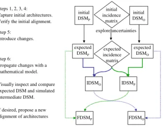
Figure 2 shows the overall flowchart of the proposed method. We denote IDSMO (resp. IDSMP) the Intermediate Organisation (resp. Product) DSM.
Figure 2 Overall flowchart of the method
expected DSMP FDSMO FDSMP IDSMO IDSMP expected DSMO initial DSMP initial DSMO Steps 1, 2, 3, 4:
Capture initial architectures. Verify the initial alignment. Step 5:
Introduce changes.
explore uncertainties
Step 6:
Propagate changes with a mathematical model. Visually inspect and compare expected DSM and simulated intermediate DSM. If desired, propose a new alignment of architectures initial incidence matrix expected incidence matrix
6 Application to an Industrial Context
In this section, we present the proposed method in detail and simultaneously, we apply it to the design of a new Robotized Gearbox, in the framework of a collaborative research project with a French automaker.
Our initial situation corresponds to the development situation of a manual mechanical gearbox. This situation will evolve since the firm makes the strategic decision to develop a Robotized Gearbox (RG) based on the mechanical one. A RG acts as an automatic gearbox while preserving the simple and cheap architecture of a manual gearbox. In a RG, there is an automated controller which shifts the speeds of a manual gearbox instead of the driver.
6.1
Capturing the initial Product Architecture
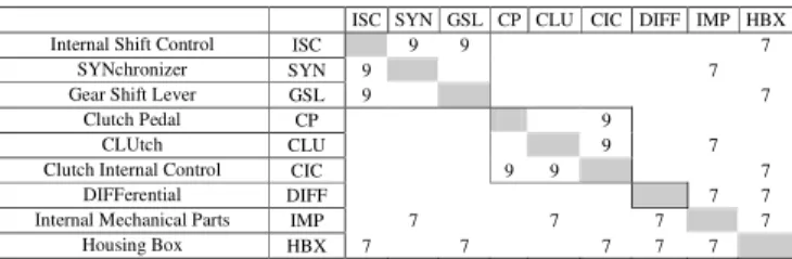
We capture the list of components and their interactions by interviewing design experts and architects who have a deep understanding of the gearbox architecture. The intensity of each interaction has been discussed and fixed according the Eppinger's typology of interactions. The manual/mechanical gearbox is decomposed into nine subsystems (or components) that are in turn decomposable into more than 100 parts. Figure 3 exhibits a component DSM of this gearbox. The clustering algorithm reveals hybrid architecture, with three modules (or modular sub-systems), and two integrative sub-systems. This architecture has been validated by the gearbox designers since they have adopted the same one. The first module (ISC, SYN, GSL) realizes the shifting function (that is linked to a strategic customer requirement: driving pleasure), the second module (CP, CLU, CIC) realizes power transmission function and the third module contains only one component which is the differential. The two remaining components are integrative. They link together all the other modules of the manual gearbox: IMP from the inside and the HBX from the outside.
Figure 3 Component DSM of the manual gearbox
ISC SYN GSL CP CLU CIC DIFF IMP HBX Internal Shift Control ISC 9 9 7
SYNchronizer SYN 9 7 Gear Shift Lever GSL 9 7
Clutch Pedal CP 9 CLUtch CLU 9 7 Clutch Internal Control CIC 9 9 7
DIFFerential DIFF 7 7 Internal Mechanical Parts IMP 7 7 7 7
Housing Box HBX 7 7 7 7 7
6.2
Capturing the initial Development Organization
We capture the development organization by identifying the technical interactions between the design teams. We surveyed component design team leaders, system function architects and managers. We asked them to rate the criticality and frequency of their interactions with one another during the detailed design phase of the gearbox development project. The numerical evaluation of the interactions is obtained through the aggregation of designers’ evaluations and it is validated by the project manager. The metric adopted allows only symmetrical evaluation and ranges from 0 to 10.
The organization responsible for the development of the manual gearbox is divided into 13 design teams or designers. There are 9 design teams directly responsible for the development of the 9 components making up the manual gearbox, 2 architects responsible respectively for shifting and coupling functions and 2 managers responsible respectively for the project management (or system architect) and for the management of technical risks and calculus. Figure 4 displays the organization DSM. When applied to the organization DSM, the clustering algorithm has identified a hybrid organization structure with 4 modular teams and 2 integrative designers (MGT, CAL). This organization structure has been validated by the gearbox development project manager.
6.3
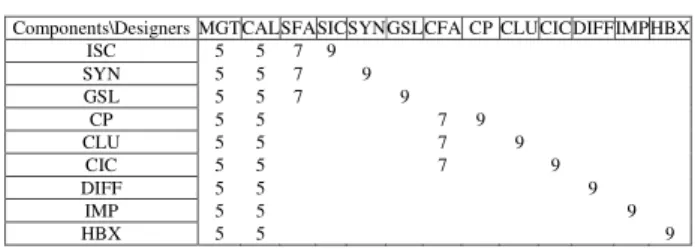
Capturing the Incidence Matrix
Incidence matrices are the cornerstone of our research work. We believe that system architects' core competence lies in its ability to build an appropriate incidence matrix early in the development process. We surveyed only system function architects and managers to fill in the Product-Organization incidence matrix for the manual gearbox. It is a "9 by 13" matrix with, listed in rows, the manual gearbox components and in columns the development leaders or designers (Figure 5).
Figure 4 Organization DSM of the manual gearbox
Designers MGT CAL SFA SIC SYN GSL CFA CP CLU CIC DIFF IMP HBX project Management MGT 9 5 5 5 5 5 5 5 5 5 5 5 Calculus and technical risks management CAL 9 5 7 7 7 5 7 7 7 7 7 7 Shifting Function Architect SFA 9 5 9 9 9 7 7 Shift Internal Control development leader SIC 5 7 9 9
SYNchronizer development leader SYN 5 7 9 9 Gear Shift Lever development leader GSL 5 7 9 9 9
Coupling Function Architect CFA 5 5 9 9 9 7 7 Clutch Pedal development leader CP 5 7 9 9
Clutch development leader CLU 5 7 7 9 9 Clutch internal control development leader CIC 5 7 9 9 9
Differential development leader DIFF 5 7 9 7 "Internal mechanical parts" development leader IMP 5 7 7 7 9
Housing box development leader HBX 5 7 7 7 7
Figure 5 Manual gearbox incidence matrix
Components\Designers MGT CAL SFA SICSYN GSL CFA CP CLU CIC DIFFIMPHBX ISC 5 5 7 9 SYN 5 5 7 9 GSL 5 5 7 9 CP 5 5 7 9 CLU 5 5 7 9 CIC 5 5 7 9 DIFF 5 5 9 IMP 5 5 9 HBX 5 5 9
6.4
Aligning the Product Architecture and Organization Structure
This step is very important for the analysis that will be undertaken after simulating the change propagation through the two project domains. Indeed, in the following steps, we will introduce change in one project domain (in our example, within the product architecture), and we will simulate new coherent architectures. The effect of change on architectures will be analyzed by comparison with the initial state. In order to be sure to analyze only change effects, we need to start from already coherent initial architectures. Verifying and realizing –if necessary- coherent initial architectures is possible by two ways, informal or formal.
Informal way - We ask system architects and component development leaders to visualize DSM and inspect the coherence between the two architectures. Even though this approach is informal and subjective, initial architectures are often issued from repetitive development experiences and may be judged as being satisfactory.
Formal way - We use the proposed method in step 6 (see later in Part 6.6) for making project domains co-evolve before introducing uncertainties. We will use the two initial DSM and the incidence matrix previously filled in by the project actors and we will simulate two new "initial DSM" ensuring architectural coherence.
In the case of the manual gearbox development, the initial architectures of product and organization are judged coherent from an informal way.
6.5
Exploring Uncertainties and introducing Changes
Technological innovations may require accommodations in the product architecture. They introduce change and uncertainties during the early phase of the design project. In our example, the need for making Product architecture and Organization co-evolve comes from the project steering committee's decision to design and launch a robotized gearbox
based on a manual one. So we need to identify and propagate the impacts of components change on the component DSM and on the organization DSM. In order to formalize and propagate change, we decide to turn to uncertainty management. Researches dealing with uncertainty management are issued from many different scientific domains: project management (Herroelen and Leus, 2005), risk management Chapman and Ward, 2002; 2003), and decision making (Erdem and Keane, 1996). This diversity makes the scientific goals multiple and different. Pich et al. (2002) model development project not as a group of tasks, but as a group of parameters (attributes) which influence the value creation in the firm. In this context, they identify five possible sources for project uncertainties: complexity, variability, risks, ambiguity, and chaos. In reference to this typology, we propose an uncertainty typology composed of three classes (Harmel et al. 2006):
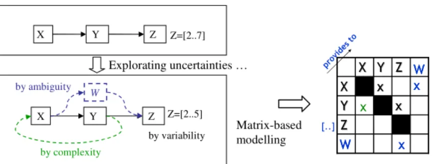
• Uncertainty by ambiguity: related to the existence or not of an element, a parameter or an entity (introduction of element W in Figure 6),
• Uncertainty by complexity: related to the existence or not of links, interactions between elements, parameters or entities (identification of a link between Y and X in Figure 6),
• Uncertainty by variability: related either to the fact of not taking into accounts some possible values of a parameter or to the fact of taking into account prohibited values (change on Z definition domain, represented by [ … ] in Figure 6).
The equivalent representation of each uncertainty with DSM is presented in Figure 6.
Figure 6 Example of uncertainties exploration
Z=[2..7] Y X Z W Z=[2..5] Y X Z Explorating uncertainties … Matrix-based modelling by ambiguity by complexity by variability
Identifying and modelling change requires three steps:
• First, explore "uncertainties by ambiguity", by identifying elements that could be new, replaced or eliminated,
• Second, explore "uncertainties by complexity" to identify the effects on expected interactions, in order to integrate or eliminate these elements within the system,
• Third, explore "uncertainties by variability" to evaluate and check all interfaces, either "well specified" or "poorly specified".
Thus, there is a hierarchical relationship between the three classes of uncertainty typology. In the example, we analyze the technological change propagation concerning the Robotized Gearbox (RG) development project by using this "uncertainty management" approach. Thus, we survey the RG system architect (project manager), in order to identify new elements and eliminated elements in the product architecture and
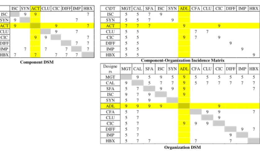
organization. Concerning the product, in order to transform a manual gearbox into a robotized one, the designers replaced the Gear Shift Lever (GSL) and the Clutch Pedal by an electrical Actuator (ACT). This modification in the gearbox architecture involved the replacement of the corresponding designers by an Actuator Development Leader (ADL). Figure 7 exhibits the result of "uncertainties by ambiguity" exploration on the component DSM, the incidence matrix and the organization DSM. We notice that in this step the interactions are not yet identified.
Figure 7 "Uncertainties by ambiguity" exploration
ISC SYN ACT CLU CIC DIFF IMP HBX C\D MGT CAL SFA SIC SYN ADL CFA CLU CIC DIFF IMP HBX
ISC ISC SYN SYN ACT ACT CLU CLU CIC CIC DIFF DIFF IMP IMP HBX HBX
Component DSM Component-Organization Incidence Matrix
Design MGT CAL SFA SIC SYN ADL CFA CLU CIC DIFF IMP HBX MGT CAL SFA ISC SYN ADL CFA CLU CIC DIFF IMP HBX Organization DSM
Second, we asked the system architect and component development leaders to evaluate or check all interactions, especially interactions with the new elements identified above. We took care of indirect change propagation linked to a "system effect". The "expected matrices" obtained are presented in Figure 8. Interactions are marked either with an (X) if they are stable, or with (●) if they are new or judged "poorly specified".
Figure 8 "Uncertainties by complexity" exploration
ISC SYN ACT CLU CIC DIFF IMP HBX C\D MGT CAL SFA ISC SYN ADL CFA CLU CIC DIFF IMP HBX
ISC X ● X ISC X X X X SYN X X SYN X X X X ACT ● ● ● ACT ● ● ● ● ● CLU X X CLU X X X X CIC ● X X CIC X X ● X X DIFF X X DIFF X X X IMP X X X X IMP X X X HBX X ● X X X HBX X X X
Design MGT CAL SFA ISC SYN ADL CFA CLU CIC DIFF IMP HBX MGT X X X X ● X X X X X X CAL X X X X ● X X X X X X SFA X X X X ● X ISC X X X ● SYN X X X ADL ● ● ● ● ● CFA X X X X X CLU X X X CIC X X ● X X DIFF X X X X IMP X X X HBX X X X X X
Component DSM Component-Organization Incidence Matrix
Organization DSM
Third, the final step concerns variability exploration which will lead us to evaluate each new or evolving interaction identified in the previous step (Figure 9). We call these matrices “expected matrices”. They are the results of manual change propagation by the development teams. However, product development situations are of high complexity
with a lot of interactions and change. Thus system architects and designer teams need an efficient way of dealing with their bounded rationality.
Figure 9 "Uncertainties by variability" exploration
ISC SYN ACT CLU CIC DIFF IMP HBX C\DT MGT CAL SFA ISC SYN ADL CFA CLU CIC DIFF IMP HBX
ISC 9 9 7 ISC 5 5 7 9 SYN 9 7 SYN 5 5 7 9 ACT 9 9 7 ACT 7 7 7 9 9 CLU 9 7 CLU 5 5 7 7 CIC 9 9 7 CIC 5 5 9 7 9 DIFF 7 7 DIFF 5 5 9 IMP 7 7 7 7 IMP 5 5 9 HBX 7 7 7 7 7 HBX 5 5 9 Designe
rs MGT CAL SFA ISC SYN ADL CFA CLU CIC DIFF IMP HBX MGT 9 5 9 5 9 5 5 5 5 5 5 CAL 9 5 7 7 9 5 7 7 7 7 7 SFA 5 7 9 9 9 7 ISC 9 7 9 9 SYN 5 7 9 ADL 9 9 9 9 9 CFA 5 7 9 9 7 CLU 5 7 9 CIC 5 7 9 9 9 DIFF 5 7 9 7 IMP 5 7 9 HBX 5 7 7 7 7
Component DSM Component-Organization Incidence Matrix
Organization DSM
6.6
Simulating new Architectures
According to different experts in the field of complex Systems Engineering (Novak and Eppinger 1998), we assumed that within the automobile industry, highly successful companies clearly mirror the organization structure in the product architecture, by comparing and coupling design interfaces with team interactions. Sosa et al. (2003) suggest that managers should pay particular attention to identifying modular and integrative systems so that the critical design interfaces between modular systems be properly identified. In this step of our method, we propose first a mathematical model to overcome the difficulty of adapting the overall project domains to local changes.
6.6.1. Propagating Changes with a mathematical Model
In this part, we propagate interactions constraints from the product architecture to the organization structure through the incidence matrix. We introduce two intermediate DSMs. IDSMO denotes the Intermediate Organization DSM, and IDSMP denotes the
Intermediate Product DSM. Let’s consider the organizational interaction IDSMO(T1,T2)
between the two design teams: T1 and T2. We assume that IDSMO(T1,T2) exists (that is,
is not null) if:
• Condition 1. There is at least one component C impacting both teams in the incidence matrix (C-T1 and C-T2 exist),
• Or Condition 2. There are two interacting components C1 and C2 (in the component DSM, C1-C2 exists) impacting respectively one of the two teams (in the incidence matrix, either C1-T1 and C2-T2 exist, or C1-T2 and C2-T1 exist).
Even if we know that it doesn't make sense that any element of a system be in interaction with itself in conventional DSM, these two conditions can be aggregated in only one if we assume that the strongest interaction of a component is with itself. Since diagonal elements of conventional DSM are meaningless, it is possible to allocate to them
the maximum value of the evaluation scale to increase the importance of the first condition.
Then we formulate the mathematical expression for the intensity of the interaction
IDSMO(T1,T2)(k,u) , as follows:
(
)
( )(
)
(
)
(
)
(
)
(
1, 2)
*(
1, 2)
*(
2, 1)
2 , 2 * 1 , 1 * 2 , 1 , max 2 , 1 2 1 2 1 2 , 1 T C INCID T C INCID C C DSM E T C INCID T C INCID C C DSM E E E T T IDSM P P C C O = = = Eq. 1where DSM and INCID correspond respectively to the intermediate DSM and the intermediate incidence matrix.
Finally, each couple of components (Ck, Cu) could contribute to the IDSMO(T1,T2) in
the simulated intermediate IDSMO . We choose to compute the intensity value of
IDSMO(T1,T2) by the average value of all the IDSMO(T1,T2)(k,u) calculated for each
couple (Ck, Cu) of the gearbox components with the possibility of having k equal to u (Eq. 2).
(
)
(
)
( ) N T T IDSM T T IDSMC
N P k u P u k O O + =∑ ∑
∈ ∈ 2 , 2 , 1 2 , 1 Eq. 2 whereC
N N+2 equals the total number of combinations.
6.6.2. Comparing expected and simulated DSM
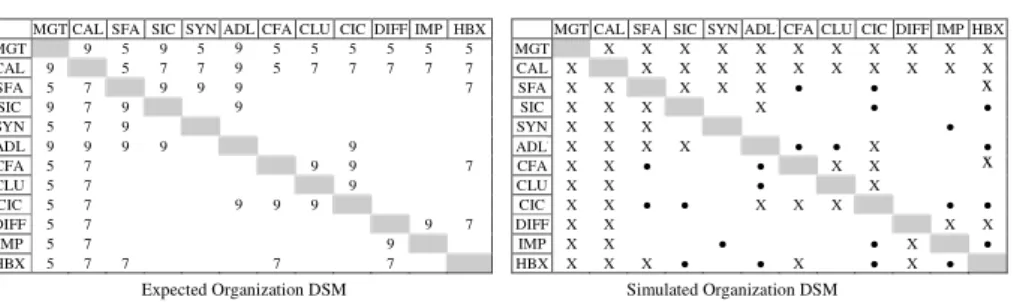
This step is important to allow system architects and designers to compare the simulated propagation of change (simulated intermediate organization DSM) to their own prediction (expected organization DSM). They have to analyze the differences and perhaps to modify one or several intermediate matrices. Differences may be accepted but we need to be aware of the potential consequences. Figure 10 shows on the left side the expected organization DSM and on the right side, the simulated intermediate organization DSM (IDSMO), obtained by propagating changes in product DSM.
Figure 10 Comparison between expected and simulated Organization DSM
MGT CAL SFA SIC SYN ADL CFA CLU CIC DIFF IMP HBX MGT CAL SFA SIC SYN ACT CFA CLU CIC DIFF IMP HBX MGT 9 5 9 5 9 5 5 5 5 5 5 MGT X X X X X X X X X X X CAL 9 5 7 7 9 5 7 7 7 7 7 CAL X X X X X X X X X X X SFA 5 7 9 9 9 7 SFA X X X X X ● ● 7 SIC 9 7 9 9 SIC X X X X ● ● SYN 5 7 9 SYN X X X ● ADL 9 9 9 9 9 ACT X X X X ● ● X ● CFA 5 7 9 9 7 CFA X X ● ● X X 7 CLU 5 7 9 CLU X X ● X CIC 5 7 9 9 9 CIC X X ● ● X X X ● ● DIFF 5 7 9 7 DIFF X X X X IMP 5 7 9 IMP X X ● ● X ● HBX 5 7 7 7 7 HBX X X X ● ● X ● X ● ADL ADL
Expected Organization DSM Simulated Organization DSM
x
x
We propose to compare expected interactions and simulated ones. The second DSM is represented in a binary form. Interactions are marked either with an (X) if they are stable or with (●) if they are new. We note that:
• The simulated DSM identifies all the designers’ interactions that are identified in the expected (initial) organization DSM. Thus, starting from the robotized gearbox DSM, we are able to find all the designers' interactions that the project manager has identified.
• This DSM identifies 11 unexpected designers’ interactions which represent 8% of all possible designers’ interactions and 34% more interactions by comparison to those expected (11 out of 32). This means that the simulated DSM shows a more complex organization than the expected one.
• The unexpected interactions can be explained differently when we analyze the initial product DSM. For example, the HBX designer is responsible for the HBX component design (Figure 5). Now, HBX component shares a large number of couplings with the other gearbox components. The propagation of all these interactions through the incidence matrix and according to the propagation model explains the new HBX designer interactions,
There are two possible ways for exploiting these intermediate DSM results. Firstly, give the project managers the possibility of analysing these results and modifying the DSM manually in order to take their choices into account. Secondly, automatically generate the final DSM by taking the initial organization DSM into account.
6.6.3. Analyzing a new Alignment of Architectures
When the intermediate matrices have been improved, we propose a new alignment of architectures by taking into account the expected and simulated organization DSM with different weights. Let’s call FDSMO the final organization DSM. Then we propose to
compute FDSMO(T1,T2) as follows:
(
)
(
)
(
)
1 2 , 1 2 , 1 2 , 1 = + + + = β α β α β α with T T IDSM T T DSM T T FDSM O O O Eq. 3The above formula allows taking into account the two possibilities mentioned in the previous paragraph. Thus, the final DSM will be the centroid between the initial DSM and the Intermediate DSM. In case of unavailable information about the initial situation,
α
is equal to 1. In case of no favourite architecture:α
=β
=0.5, this last configuration will be used in the following development of the paper.In order to identify new architectures of product and organization, we use a clustering algorithm based on an algorithm developed by Idicula (1995) and improved by Fernandez (1998) and Thebeau (2001). Idicula's algorithm assumes an underlying directed graph model for the development effort, and uses a depth-first-search technique to solve the problem. It groups the “project tasks into clusters that are loosely connected with each other, while each cluster consists of densely connected inter-coupled tasks”. The improved algorithm contains a simulated annealing procedure allowing a larger exploration of acceptable solutions than Idicula's one.
6.7
Application to the Robotized Gearbox development situation
In this part, we present the application of the proposed method to the peculiar RG development situation.
6.7.1. Simulating Changes Propagation from Product Architecture to Organization Structure
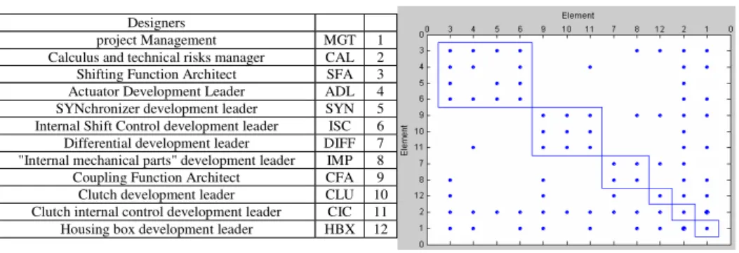
The development organization structure obtained by simulating change propagation is presented in Figure 11 (numerical coupling values are represented by the size of the
diamonds). The clustering algorithm identifies 3 organizational modules (teams) and 3 integrative designers. By comparison to the initial organization structure, the effects of change propagation are a little perceptible only. However, the new designer in charge of the actuator development is identified by the clustering algorithm as better belonging to the first team (SFA, SYN, ISC and ADL). We note several important points:
• The actuator designer interacts with the CIC designer as identified in the uncertainty exploration step.
• The two other teams identified correspond to coupling function (CFA, CLU and CIC) and a team composed of two designers in charge of the DIFF and IMP development. • The clustering algorithm highlights three integrative designers as expected: the project manager (MGT, 1), the leader in charge of calculus and risks management (CAL, 2), the housing designer (HBX, 12). The first two designers are integrative through the need in their work to communicate with all the other designers participating to the robotized gearbox development, the third through the integrative characteristic of the housing component.
Figure 11 Robotized gearbox organization structure
Designers
project Management MGT 1 Calculus and technical risks manager CAL 2 Shifting Function Architect SFA 3 Actuator Development Leader ADL 4 SYNchronizer development leader SYN 5 Internal Shift Control development leader ISC 6 Differential development leader DIFF 7 "Internal mechanical parts" development leader IMP 8 Coupling Function Architect CFA 9 Clutch development leader CLU 10 Clutch internal control development leader CIC 11 Housing box development leader HBX 12
6.7.2. Simulating Change Propagation from Organization Structure to Product Architecture
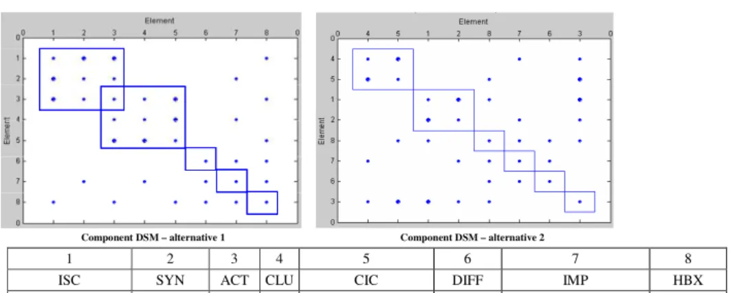
In a similar way, we simulate the change propagation from the development organization (modelled by the expected organization DSM) to the product architecture. The objective is to study the influence of organization design on the product architecture. We could expect that this projection will cover the expected interfaces within the product. That means that the chosen organization structure will be able to handle all technical interfaces. In this paper, we sum up the results and present the alignment only. Figure 12 displays two clustered DSM (with total coupling costs that are close) for two possible alternatives concerning the product architecture (after propagating the expected changes in the organization structure).
We can note that these two alternatives are very close. The main difference lies on the position of the electrical actuator (ACT), which could play either as a pivotal role between two overlapping modules (alternative 1) or an integrative role (alternative 2). By comparison to the initial manual gearbox architecture, the latter robotized gearbox architecture reveals the central and integrative role of the actuator. This confirms that the responsibilities attributed to the actuator development leader are consequent.
Figure 12 Robotized Gearbox component DSM
Component DSM – alternative 1 Component DSM – alternative 2
1 2 3 4 5 6 7 8
ISC SYN ACT CLU CIC DIFF IMP HBX
Internal Shift Control Synchronizer ActuatorClutchClutch Internal Control DifferentialInternal Mechanical PartsHousing Box
6.8
Discussion
We call co-evolution of two domains the bi-directional change propagation from one domain to the other and vice versa. The aim is to help system architects to visualize change propagation and align the two domains he is responsible for (product architecture, development organization). In the above example, the co-evolution of them in the robotized gearbox development situation leads to the following conclusions:
• We identify two alternatives for the product architecture, but only one organization structure,
• The integrative role of electric actuator in the product architecture does not influence the overall organization structure that is robust facing this component change,
• Furthermore, in order to analyze these resulting architectures and to validate our proposed method (at least on this application, in case of component changes in the product architecture), we presented our change propagation results and comments to the RG project manager and component development leaders. They all concluded with the relevance of the proposed architectures, especially concerning the pivot role of the actuator component and the need for the actuator designer to belong to the System Function design team,
• The project manager has assigned the Actuator Development Leader to the shifting function design team (module SFA, ADL, ISC, SYN) even though the actuator is integrative. This decision has been motivated, on the one hand by the high importance of this system function to satisfy customer requirements related to the gearbox performance and the high contribution of the electrical actuator to fulfil this function, and on the other hand to favour information exchanges (particularly in RG modelling) and the development of core competence.
Project integration implies change propagation between project domains. In order to facilitate complex system design and limit inappropriate feedbacks, we propose a method that allows change propagation between the architectures of two project domains. Identifying the architecture of each project domain at the early stages of the design process helps the designers in decision making (product modularisation and building of design teams). Balachandra (2002) describes how modular design can accommodate technological innovations. The author states that a high coefficient of modularity enables the company to quickly introduce technological innovations with less effort and cost
throughout the design projects. The industrial example presented in this paper seems to validate this statement. Indeed, the RG development situation is related to both initial hybrid architecture and hybrid organization structure. This favours change propagation and architecture adaptation.
7 Conclusions and future works
Complex Systems Engineering is facing continuous technological evolution that involves new generations of product and organizational changes (creation of new sort of design teams, design of new manner to coordinate them…). A brief literature review points out that simulating change propagation within a modular product architecture and aligning product architecture and development organization have received little research attention, even if several experts in the field of engineering design have highlighted the importance of these issues. In this paper, we have presented a method to help managers propagate change and simulate the co-evolution of product architecture and development organization. We have used two intra-domain matrices (DSM that provide a powerful representation of system architecture), and one inter-domains matrix (similar to axiomatic design matrix) for modelling product- and organization architectures. We have proposed to explore different types of uncertainties to model and propagate change from one domain to the other one. Finally, we have proposed a mathematical model to simulate the effects of change in one domain on the interactions in the other one. We have highlighted the key role that the inter-domains matrix can play to make two domains co-evolve. The method is applied on the development situation of a new gearbox. This industrial case study only concerns component changes but it illustrates the power of this method. We do not intend to replace managers' expertise in defining product architecture or organization structure at the system level, but rather to support the simulation of change propagation to help them carry out this difficult but crucial managerial task.
This research work needs further development. As we assume that the notion of "optimal" organization does not make sense, we intend to develop a method to help system architects to co-design product architecture and development organization semi-automatically and iteratively.
First, even if the proposed method seems to be adequate for hybrid systems architectures, we are aware of the need for further formal and experimental validations. Thus, mathematical studies will be conducted to highlight the properties and the limits of the use of this matrix-based model, especially depending on the density of the matrices. Further industrial experiments have been planned too. We need to define new criteria and metrics to estimate the relevance of architectures. Interesting product modularity indexes can be found in the literature but criteria as the frequency or importance of team interactions are not sufficient in the organization domain.
Second, we intend to improve change modelling by (1) introducing the likelihood and impact of technical risks (in a similar way to (Clarkson et al. 2004)), and (2) taking into account the types of interactions and flows within the product. Concerning development organization, the difficulty to accommodate change could be estimated by modelling relationships between change impact and designers' skills.
Third, the DSM and incidence matrix have to be filled in by system architects and design team leaders. Discussions may be necessary to identify actual interactions and to estimate each intensity value. Since intensity values may be imprecise and subjective, we are clearly in a context where the use of Fuzzy Logic is relevant. We are under progress
to develop a fuzzy inference system in order to handle these matrices. Then the proposed mathematical model will be replaced by a set of fuzzy rules that will approximate the way an architect estimates the coupling between two domains.
Fourth, it will be interesting to extend the use of this method in order to propagate changes through the three project domains: product, organization and processes.
References
Alexander C. (1964) Notes on the Synthesis of Form. Harvard University Press, Cambridge, MA. Avak B. (2006), ‘Life cycle adaptation of modular product families’, 1st Nordic Conference on
Product Lifecycle Management, Goteborg.
Balachandra, R. (2002) ‘Modular Design and Technological Innovation: The Case of the Hard Disk Drives’, Report 2002-02, The Information Storage Industry Center, University of California, http://isic.ucsd.edu, December.
Browning, T.R. (2001) ‘Applying the design structure matrix to system decomposition and integration problems: A Review and New Directions’, IEEE Trans. Eng. Mgt., Vol. 48, No .3, pp. 292-306.
Carrascosa, M., Eppinger, S. D. and Whitney, D. E. (1998) ‘Using the design structure matrix to estimate product development time’, in Proc. ASME Des. Eng. Tech. Conf. (Design
Automation Conf.), Atlanta, GA.
Chapman, C.B. and Ward, S.C. (2002) Managing Project Risk and Uncertainty: A Constructively
Simple Approach to Decision Making. Wiley: Chichester.
Chen, S.J. and Lin, L. (2003) ‘Decomposition of interdependent task group for concurrent Engineering’, Computers & Industrial Engineering, Vol. 44, pp. 435–459
Chen, S.J. (2005) ‘An Integrated Methodological Framework for Project Task Coordination and Team Organization in Concurrent Engineering’, Concurrent Engineering: Research and
Applications, Vol. 13, No. 3, pp.185-197.
Chen, K.M and Liu, R.J. (2005) ‘Interface strategies in modular product innovation’, Technovation, Vol. 25, pp. 771–782.
Cho, S-H. (2001) An Integrated Method for Managing Complex Engineering Projects Using the
Design Structure Matrix and Advanced Simulation. Master of Science Thesis, MIT, 2001.
Clarkson, P.J., Simons, C.S. and Eckert, C.M. (2004) ‘Predicting change propagation in complex design’, in ASME Journal of Mechanical Design, Vol. 126, No. 5, pp.765-797.
Dahmus, J. B., Gonzalez-Zugasti, J. P., Otto, K.N. (2001) ‘Modular Product Architecture’, Design
Studies, Vol. 22, No. 5, pp.409-424.
David, M., Idelmerfaa, Z. and Richard, J. (2002) ‘Organization method for complex cooperative design projects’, IEEE International Conference Systems, Man and Cybernetics, Hammamet, Tunisia.
Danilovic, M. and Browning, T.R. (2007) ‘Managing complex product development projects with design structures matrices and domain mapping matrices’, International Journal of Project
Management, Vol. 25, pp.300–314.
Eppinger, S. D., Whitney, D. E., Smith, R. P. and Gebala, D. A. (1994) ‘A Model-Based Method for Organizing Tasks in Product Development’, Research in Engineering Design, Vol. 6, No.1, pp.1-13.
Eppinger, S. D. (1997) ‘A Planning Method for Integration of Large-Scale Engineering Systems’,
International Conference on Engineering Design (ICED 97 Tampere).
Eppinger, S.D., and Salminen, V. (2001) ‘Patterns of product development interactions’, Int. Conf.
on Engineering Design, ICED 01, Vol. 1, Glasgow, August 21-23, pp.283-290.
Erdem, T. and Keane M.P. (1996), “Decision Making Under Uncertainty: Dynamic Brand Choice Processes in Turbulent Consumer Goods Markets,” Marketing Science, Vol.15, No 1, pp.1–20.
Fernandez, C. (1998) Integration analysis of product architecture to support effective team
co-location. Master of Science Thesis, MIT, USA.
Fitzpatrick, E.L. and Askin, R.G. (2005) ‘Forming effective worker teams with multi-functional skill requirements’, Computers & Industrial Engineering, Vol. 48, pp.593–608
Fixson, S.K. (2005) ‘Product architecture assessment: a tool to link product, process and supply chain design decisions’, Journal of Operations Management, Vol. 23, pp.345-369
Galbraith, J.R. (1977) Organization Design Addison-Wesley, Reading, Mass
Galbraith, J. R. (1994) Designing Organizations: an Executive Briefing on Strategy, Structure, and
Process, Jossey-Bass Inc., San Fransisco.
Henderson, R. and Clark, K. (1990), ‘Architectural Innovation: The Reconfiguration of Existing Product Technologies and the Failure of Established Firms’, Adm. Sci. Q., Vol. 35, pp. 9–30. Herroelen, W. and Leus, R. (2005) ‘Project scheduling under uncertainty ––survey and research
potentials’, Research report 0225, Department of Applied Economics, K.U. Leuven, European
Journal of Operational Research, Vol. 165, pp.289–306.
Hölttä-Otto, K. (2005) Modular product platform design. PhD, Helsinki University of Technology, Espoo, Finland, ISBN 951-22-7766-2.
Idicula, J. (1995) Planning for concurrent engineering, Thesis draft, Nanyang Technology University.
IEEE Std 1220™, Standard for application and Management of the Systems Engineering Process. IEEE Computer Society, Revision of IEEE Std 1220-1998, 2005.
Jiao, J., Simpson, T., and Siddique, Z. (2006) ‘Product family design and platform-based product development: a state-of-the-art review’, Journal of intelligent manufacturing, special issue on
Product family design and platform-based product development.
Keller, R., Eckert, C.M. and Clarkson, P.J. (2005) ‘Visualising change propagation’, Proc. 15th
International Conference on Engineering Design (ICED'05), Melbourne, Australia.
Kusiak, A. and Huang, C.C. (1996) ‘Development of Modular Products’, IEEE Transactions on
components, packaging and manufacturing technology – part A, Vol. 19, No. 4, pp. 523-538.
Lindemann, U. and Reichwald, R. (eds.) (1998) ‘Integriertes Änderungsmanagement’, Springer, Berlin.
Lindemann, U. (2007) ‘A vision to overcome chaotic "design for X" processes in early phases’,
Proc. Int. Conf. Engineering Design, ICED’07, 28 - 31 August, Paris.
Malmqvist, J. (2002) ‘A classification of matrix based methods for product modelling’ Design
2002, 14-17, Cavtat-Dubrovnik, Croatia.
McCord, K. R. and Eppinger, S. D. (1993) ‘Managing the Integration Problem in Concurrent
Engineering’, M.I.T. Sloan School of Management, Cambridge, MA, Working Paper no.3594.
Meinadier, J-P. (2002) Le métier d'intégration de systèmes, Hermès Sciences Publications.
Oosterman, B. (2001) Improving Product Development Projects by Matching Product Architecture
and Organization, PhD thesis, Gröningen University, The Netherlands, ISBN: 90-72591-99-2.
Pich, M., Loch, C. De Meyer, A. (2002) ‘On uncertainty, ambiguity, and complexity in project management’, Management Sci. Vol. 48, No. 8, pp.1008–1023.
Pimmler, T. U. and Eppinger, S. D. (1994) ‘Integration Analysis of Product Decompositions’,
Proceedings ASME Design Theory and Method Conference (DTM'94), Vol 68, pp. 343-351.
Robin, V., Rose B. and Girard P. (2007), ‘Modelling collaborative knowledge to support engineering design project manager’, Computers in Industry, Vol. 58, pp.188–198
Sanchez, R. and Mahoney, J.T. (1996) ‘Modularity, flexibility and knowledge management in product and organization design’, Strategic Management Journal. Vol. 17, pp. 63-76.
Sharman, D.M. and Yassine, A. (2004) ‘Characterizing Complex Product Architectures’, Systems
Sosa, M.E., Eppinger, S.D. and Rowles C.M. (2000) ‘Designing modular and integrative systems’,
Proceedings of DETC '00: ASME 2000 International Design Engineering Technical Conferences.
Sosa, M., Eppinger, S.D. and Rowles C. (2003) ‘Identifying modular and integrative systems and their impact on design team interactions’, Transactions of the ASME, Vol. 125, pp. 240-252
Steward, R. P. and Donald V. (1981) ‘The Design Structure System: A Method for Managing the Design of Complex Systems’, IEEE T. on Engineering Management Vol. 28, No.3, pp. 71-74.
Stone, R., Wood, K. and Crawford, R. (2000) ‘A Heuristic Method for Identifying Modules for Product Architectures’, Design Studies, Vol. 21, pp.5-31.
Suh, N. P. (1990) Principles of Design, Oxford University Press, Cambridge, UK.
Thebeau R. Knowledge management of system interfaces and interactions for product development
processes. Master of Science Thesis, MIT, 2001.
Tseng, T.L., Huang, C.C., Chu, H.W. and Gung, R.R. (2004) ‘Novel approach to multi-functional project team formation’, International Journal of Project Management, Vol. 22, pp.147–159
Ulrich, K.T. (1995) ‘The Role of Product Architecture in the Manufacturing Firm’, Research
Policy, Vol. 24, pp.419-440.
Van Wie, M., Greer, J., Campbell, M., Stone, R. and Wood, K. (2001)’Interfaces and Product Architecture’, ASME Design Engineering Technical Conference Proc., DETC01/DTM-21689.
Ward, S.C. and Chapman, C.B. (2003) ‘Transforming project risk management into project uncertainty management’, Int. J. Proj. Mng. Vol. 21, pp.97–105.
Whitfield, R.I., Smith, J.S. and Duffy, A.H.B. (2002) ‘Identifying Component Modules’, In
Proceedings of Seventh International Conference on Artificial Intelligence in Design (AID’02), Cambridge, United Kingdom, pp. 571-592.
Whitfield, R.I., Duffy, A.H.B. and Gartzia-Etxabe, L.K. (2005) ‘Identifying and evaluating parallel design activities using Design Structure Matrix’, Proc. ICED 05 Melbourne, August 15-18.
Yassine, A. and Braha, D. (2003) ‘Complex concurrent engineering and Design Structure Matrix method’, CERA, Vol. 11, No. 3, pp. 165-176.
Yu, T., Yassine A. and Goldberg D. (2003) ‘Genetic algorithm for developing modular product architectures’, In Proc ASME 15th Int Conf Des Theory Methodology, Chicago, September.