Titre:
Title:
From flapping wings to underactuated fingers and beyond: a broad
look to self-adaptive mechanisms
Auteurs:
Authors
: Lionel Birglen
Date: 2010
Type:
Article de revue / Journal articleRéférence:
Citation
:
Birglen, L. (2010). From flapping wings to underactuated fingers and beyond: a broad look to self-adaptive mechanisms. Mechanical Sciences, 1(1), p. 5-12. doi:10.5194/ms-1-5-2010
Document en libre accès dans PolyPublie
Open Access document in PolyPublieURL de PolyPublie:
PolyPublie URL: https://publications.polymtl.ca/3401/
Version: Version officielle de l'éditeur / Published version Révisé par les pairs / Refereed Conditions d’utilisation:
Terms of Use: CC BY
Document publié chez l’éditeur officiel
Document issued by the official publisher
Titre de la revue:
Journal Title: Mechanical Sciences (vol. 1, no 1) Maison d’édition:
Publisher: Copernicus Publications URL officiel:
Official URL: https://doi.org/10.5194/ms-1-5-2010 Mention légale:
Legal notice:
Ce fichier a été téléchargé à partir de PolyPublie, le dépôt institutionnel de Polytechnique Montréal
This file has been downloaded from PolyPublie, the institutional repository of Polytechnique Montréal
doi:10.5194/ms-1-5-2010
© Author(s) 2010. CC Attribution 3.0 License.
Mechanical
Sciences
Open AccessFrom flappin wings to underactuated fin ers and
beyond: a broad look to self-adaptive mechanisms
L. Birglen
Ecole Polytechnique of Montreal, Department of Mechanical Engineering, Ecole Polytechnique of Montreal, Montreal, QC, H3T 1J4, Canada
Received: 7 March 2010 – Revised: 29 June 2010 – Accepted: 19 August 2010 – Published: 22 December 2010
Abstract. In this paper, the author firs reviews the different terminologies used in underactuated grasping and illustrates the current increase of activity on this topic. Then, the (probably) oldest known self-adaptive mechanism is presented and its performance as an underactuated finge is discussed. Its original application, namely a fl pping wing, is also shown. Finally, it is proposed that the mechanisms currently used in under-actuated grasping have actually other applications similarly to the previously discussed architecture could be used for both an underactuated finge and a flappin wing.
This paper was presented at the IFToMM/ASME International Workshop on Underactuated Grasping (UG2010), 19 August 2010, Montr´eal, Canada.
1 Self-adaptive, adaptive, intelligent, underactuated, differential, or compliant?
Self-adaptive mechanisms as used in underactuated fin gers (Birglen et al., 2008) are often confused with other classes of mechanisms because of the lack of a clear defi nition. According to Gosselin (2006), adaptive mechanical systems are define as systems “in which the ability to adapt
to new external situations relies strictly on mechanical prop-erties” (quoted). Although the denomination of “adaptive
mechanisms” proposed in the latter reference is absolutely correct, the author of this paper often prefers referring to them as “self-adaptive mechanisms” to avoid confusion. In-deed, the latter expression emphasizes that the adaptation ca-pability refers to the mechanical system itself and does not describe an algorithmic procedure. As noted in Gosselin (2006), adaptive systems are usually associated with com-puter systems and this has lead to some confusion in underac-tuated grasping. It should also be noted that “self-adaptive” has already been used by other authors to describe these sys-tems (Rubinger et al., 2001; Carrozza et al., 2004). They are also sometimes referred to as “intelligent” systems (Ulrich, 1988; Gosselin, 2005), which is more vague and therefore, should probably be avoided.
Correspondence to: L. Birglen
(lionel.birglen@polymtl.ca)
The objective of self-adaptive mechanisms is to delegate part of the control tasks from the electronic board to the mechanical layout of the system itself. Hence, with self-adaptive robotic hands, parts of the possible motions of the finger have to be uncontrolled electronically. However, these motions must be carefully predicted and studied in or-der to achieve the desired closing sequence, or else, they can lead to degenerate behaviours (Birglen and Gosselin, 2006b). Since some degrees of freedom (DOF) of these hands are not controlled, they are often referred to as “underactuated” (Lal-ibert´e and Gosselin, 1998). Again, this adjective is techni-cally correct but has also lead to some confusion. Under-actuation in robotic hands is different from the concept of underactuation usually presented in robotic systems and the differences between both notions should be made clear. An underatactuated serial robot is define as a manipulator with one or more unactuated joints. On the other hand, “under-actuated” or self-adaptive finger use passive elements (the most common of which are springs) in the design of their un-actuated joints. Thus, one should rather think of these joints as uncontrollable or passively driven instead of unactuated.
With self-adaptive robotic systems, and conversely to usual underactuated manipulators, the actuation torque (or force) is distributed to each joint of the system. This distri-bution property is essential and can be related to the Trans-mission matrix of the linkage (Birglen, 2009) which is char-acteristic of the type of transmission mechanism required to achieve this distribution. In principle, this distribution
6 L. Birglen: From flappin wings to underactuated finger and beyond Self-Adaptive robotic finger Connected mechanism differential output output output input Robotic finger
Figure 1. A connected differential mechanism driving a robotic finge .
property is similar to the behaviour of differential mecha-nisms. Let us recall that according to the IFToMM termi-nology (IFToMM, 1991), a differential mechanism is a two-DOF mechanism that may resolve a single input into two out-puts and vice versa. Therefore, if more than two outout-puts are required – typically three with robotic finger (for three pha-langes) – the simplest approach is to stack multiple differen-tial devices, each stage adding one DOF to the system (Hi-rose, 1985; Birglen and Gosselin, 2006c). An illustration of this process is given in Fig. 1, the outputs of two differen-tial seesaw mechanisms (middle, presented in Birglen and Gosselin (2006c)) connected in series drive a robotic finge (left) resulting in a well-known architecture of self-adaptive robotic finge (right), proposed in Gosselin and Lalibert´e (1996) and consequently used in several prototypes (Lalib-ert´e et al., 2002).
However, the designs obtained with this method are only a small sample of a vastly larger number (literally thousands) of possible mechanisms with equal or less complexity (Bir-glen, 2009). Hence, differential mechanisms is also not the best term to describe self-adaptive mechanisms.
Passive elements are the second ingredient to self-adaptation and are used to kinematically constrain the sys-tem. Strictly speaking, the inclusion of a specifi pas-sive element is not absolutely necessary to achieve self-adaptation since inertial properties can be used as “passive elements” (Birglen, 2009). In this particular case, the result-ing linkage is close to the meanresult-ing of underactuation com-monly found in the literature. However, to the best of the author’s knowledge only two prototypes of self-adaptive fin gers have importantly relied on dynamic parameters such as inertia, namely from Higashimori et al. (2005); Crisman et al. (1996). Since the most common passive element by far is the spring (preloaded or not), it has been deemed manda-tory. This is not true, compliance is not at all necessary. For instance, other passive elements are presented in Birglen (2009).
As mentioned before, underactuation in grasping has lead to some misconception in the past as to which systems it
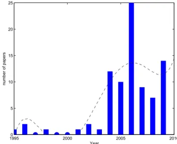
de-19950 2000 2005 2010 5 10 15 20 25 Year number of papers
Figure 2.Publication activity in underactuated grasping.
scribed because “underactuation” was associated with under-actuated manipulators. This has lead the author to start using “self-adaptive” with an increased frequency. However, this might not be necessary in the coming years as underactuation in grasping is getting more well-known. Indeed, the num-ber of papers published on underactuation in grasping has been steadily increasing in the past few years as illustrated in Fig. 2. The data from this figur have been obtained by searching the following terms on all the available databases from the Engineering Village Database1:
(((underactuated) OR (self-adaptive)) AND ((hand*) OR (finger* OR (gripper*))) WN TI
Note that the duplicates and obviously out of scope entries have been manually removed. The total number of references found with this search is 85. Of course, the results of this search engine are not complete. For instance, well-known prototypes such as the ones discussed by Hirose and Umetani (1978); Townsend (2000); Kyberd et al. (2001) do not ap-pear. Additionally, the author’s own database of publications has recently reached 500 entries (excluding patents) on un-deractuated grasping and related topics. However, this test is representative of the level of activity on this topic and has the advantage of being repeatable by anyone (thus verifiable) The author is pondering the diffusion of his database of pub-lications on a public website similarly to what Prof. Bonev did with the ParalleMIC2 for parallel mechanisms. One can
see that during the last ten years, the number of publications on underactuated grasping exploded and this area of research is now not anecdotal anymore. Nevertheless, it is also obvi-ous that it is not yet a “mainstream” issue in robotics. It is the author’s opinion that we are only at the beginning of the
1http://www.engineeringvillage2.org 2http://www.parallemic.org/
compliant joint
phalanges pulleys
cable
sliding joint (?)
Figure 3.Mechanical wing from Da Vinci’s Codex Atlanticus (ca 1496) annotated by the author.
curve illustrated in Fig. 2 and that a new trend in robotics is emerging for underactuation in grasping is only a small sam-ple of the possible applications of self-adaptive mechanisms. As an example to illustrate this claim, let us consider the old-est self-adaptive linkage known to the author: Da Vinci’s ar-ticulated wing (Birglen et al., 2008).
2 Da Vinci’s linkage
2.1 Introduction
Leonardo Da Vinci proposed in the Codex Atlanticus a mech-anism illustrated in Fig. 3 based on a cable and pulleys that was intended to drive an artificia wing in one of the fantastic flyin machine developed by the Renaissance genius.
It is unknown if such a wing or machine has ever been actually tested let alone built by Da Vinci but it proves the ingenuity of engineers before the discovery of electrical actu-ators. The mechanism itself consist of several sections, simi-lar to phalanges, whose motion was driven by a cable pulled by the human pilot of the machine. This cable was attached to the distal phalanx and ran through the phalanges with the help of pulleys or (maybe) sliding joint. The actual design of this wing bears a striking similarity with an anatomic sketch of the human finge found in another of Da Vinci’s codex (see Birglen et al., 2008, for a comparison). More than four hundred years later a very similar design was patented for a robotic finge (Rovetta et al., 1982). The firs prototype of modern underactuated fi gers, namely the Soft-Gripper of Prof. Hirose (Hirose and Umetani, 1978), was also an archi-tecture in which a cable is run through a series of pulleys until the distal end of the finge . Although in that case, the similarity between the two mechanisms ends here since the actual design of the Soft-Gripper is quite different from Da Vinci’s architecture. It is nonetheless interesting to note that this firs modern prototype which popularized
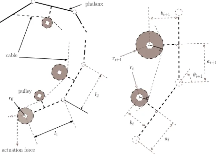
underactua-actuation force cable pulley l1 l2 phalanx ri ri+1 bi+1 θi+1 ai+1 bi ai r0
Figure 4.Da Vinci’s mechanism.
tion in grasping among the research community shares many traits with Da Vinci’s linkage.
2.2 Grasping
The architecture discussed in this section is shown in Fig. 4, and corresponds to a general model of the drawing found in the Codex Atlanticus. Notice that all the pulleys of this linkage can freely rotate around their axes.
The Transmission matrix of this mechanism is Birglen et al. (2008): T = 1 Rr1 0 R2 r0 ... R n−1 r0 0n−1 1n−1 (1) where0n−1and1n−1are respectively the null vector and iden-tity matrix of dimension n−1. The radius of a pulley equiv-alent to the i-th transmission stage (illustrated in the right-hand side of Fig. 4) is noted Rifor i = 1,..,n−1. The linkage is driven by a base pulley (with a radius r0) illustrated in the
left-hand side of Fig. 4. It can be shown that the equivalent radius of the i-th transmission stage is
Ri= ri+bi(rb−al)−(la2+bi−2ai)(ar+bl) (2) with
r = ri+1−ri, (3)
a = li−ai+ai+1cosθi+1−bi+1sinθi+1, (4)
b = −bi+ai+1sinθi+1+bi+1cosθi+1, (5)
l =√a2+b2−r2. (6)
When computing this equivalent radius, one must take into account that the points where the cable comes in contact with the pulleys ri and ri+1 is variable and depend on the angle θi+1. Similarly to the analysis of the Soft Gripper presented in (Birglen et al., 2008), the conditions for the forces to be-come zero are implicit functions that cannot be easily solved.
8 L. Birglen: From flappin wings to underactuated finger and beyond
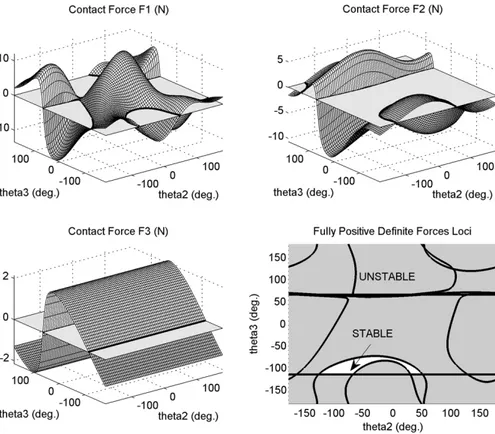
Figure 5.Contact forces and stability loci of Da Vinci’s mechanism. A section of the contact force workspace of the three-phalanx finge based on Da Vinci’s drawing is illustrated in Fig. 5 for contact locations at mid-phalanx. The geometric parameters used in this example are directly measured from a copy of the
Codex Atlanticus drawings. Note that conversely to the
anal-ysis of the same architecture found in (Birglen et al., 2008), the parameters used in this paper are these that are illustrated in the lower part of Fig. 3, i.e. with a zero-radius pulley which models a sliding joint. It seemed to be the preferred design of Da Vinci since he used it in several other sketches of his flyin machines.
As can be seen in Fig. 5, the fully positive workspace – i.e. the part of it corresponding to the case where all the contact forces are positive or null – of this architecture is rather small. This is especially true when comparing to Prof. Hirose’s Soft Gripper. However, as discussed in Birglen and Gosselin (2006b), a fully positive workspace for three-phalanx finge might be actually impossible and more impor-tantly, not really desirable. The analysis of the grasp stability of the finge which aims at predicting if the mobility of a self-adaptive finge will converge to a stable equilibrium or towards ejection of the object from the finge is more mean-ingful. Yet, this analysis is challenging especially with three-phalanx finger (Birglen and Gosselin, 2006a). In this paper, focus is placed on the analysis of a simpler two-phalanx ver-sion of the finge , using the grasp-state plane. The geometric parameters associated with this design are listed in Table 1.
Table 1.Da Vinci’s two-phalanx mechanism geometric parameters.
l1 l2 r0 a1 b1 r1 a2
1 2.06 1.03 2.08 0 0 .45
The grasp-state plane shows if, for an arbitrary initial con-tact situation, the finge will be stable or not. And, if not, if the subsequent motion undergone by the fin er will converge towards a stable equilibrium or ejection. The initial and fi nal grasp-state associated with the finge under scrutiny are illustrated in Figs. 6 and 7. In the initial grasp-state plane, the areas in gray indicate that at least one contact force is negative which means that a full enveloping grasp with both phalanges is impossible. Then, a sliding motion of the finge along the surface of the object will begin and either reach a situation where the finge is in static equilibrium (resulting in a stable pinch grasp) or lose the object (ejection). In Fig. 7, the areas in gray correspond to ejection while the white zones indicate an eventual static equilibrium. As can be seen, the finge is mostly stable for negative angles of the distal pha-lanx which is not usually the part of the workspace where the finge is used.
0 0.1 0.2 0.3 0.4 0.5 0.6 0.7 0.8 0.9 1 −π −3π/4 −π/2 −π/4 0 π/4 π/2 3π/4 π STABLE UNSTABLE θ2 k2 / l2 Hyperflexion
Figure 6.Initial grasp-state plane of Da Vinci’s finge .
0 0.1 0.2 0.3 0.4 0.5 0.6 0.7 0.8 0.9 1 −π −3π/4 −π/2 −π/4 0 π/4 π/2 3π/4 π EJECTION θ2 k2 / l2 STABLE
Figure 7.Final grasp-state plane of Da Vinci’s finge . 2.3 Flying
From the results of the previous section, we can say that the architecture of Da Vinci makes a poor underactuated finge . Using the same type of transmission, the Soft-Gripper archi-tecture is a far better choice and generally speaking, an ex-cellent gripper. Of course, to be fair, Da Vinci intended his design to be part of a flyin machine not a grasping finge so we cannot belittle his invention. For his particular appli-cation, Da Vinci also used the shape-adaptation property of the linkage but from an aerodynamic perspective not grasp stability. For a flappin wing, the finge is “in contact” with the air or another fluidi environment. The general motion of a self-adaptive flappin wing constituted of two phalanges is illustrated in Fig. 8. The revolute joint between the two pha-langes is equipped with a torsional spring and a mechanical limit. Note that the transmission mechanism achieving this
Figure 8. General motion of a self-adaptive flappin wing, the green curved arrows indicate the resistance of the flui while the red straight arrow symbolize actuation.
motion is not shown for it can take many form, Da Vinci’s being one but any other self-adaptive linkage proposed in the literature could be used. If one looks closely to the sketches made by Da Vinci, it is obvious that the human operator of the machine was to provide the actuation force required to the down stroke of the motion while compliant hinges based on cantilever beams were designed to provide the return ac-tuation (cf. Fig. 3). Thus, the idea of using compliant joints in underactuated finger must be attributed to Da Vinci. This is particularly humbling to note while this idea is recently ac-tively studied by several authors including the one of this pa-per (Dollar and Howe, 2006; Boudreault and Gosselin, 2006; Doria and Birglen, 2009).
If considering the values of the contact forces was of in-terest for a grasping finge , in the case of a flappin wing, the torque distributed by the actuator at the base joint of each phalanx might be a more practical quantity. These torques are obviously linked to the contact forces and they are ex-pressed by another form of the Transmission matrix pre-sented in Birglen (2009). However, to establish the upward force developed by this flappin wing, one needs a model for the air/flui resistance as a function of the shape of the wing and its velocity. This is also necessary to ensure that the motion of the wing will be optimal. The aerodynamic of a f apping wing is a very complex problem and there are only a few non-numerical models available, e.g. in Madan-gopal et al. (2004). The characterization of the performance of a flappin wing using a self-adaptive linkage is yet an open issue.
10 L. Birglen: From flappin wings to underactuated finger and beyond
Figure 9.A self-adaptive gripper based on architecture C234.
3 Other mechanisms and other applications
The mechanisms synthesized for underactuated grasping do not necessarily have to be used as architectures of robotic finger or flappin wings using a design based on phalanges. Even for grasping, one can use these mechanisms to syn-thesize new grippers, as illustrated in Fig. 9. The grip-per presented in this figur corresponds to the architecture
C234 (Birglen, 2009) and has two-DOF driven by a single
actuator. A spring is used as a passive element to constrain the mechanism (it can be used to keep both jaws synchro-nized during the pregrasping phase), while the leftmost pris-matic joint is actuated. A similar mechanism has been pro-posed to drive two self-adaptive finger (Birglen and Gos-selin, 2006c). Indeed, self-adaptive systems can be con-nected together to obtain new architectures and this holds for any mechanism properly designed, i.e. not only with dif-ferential mechanisms. In the example depicted in Fig. 9, the driven system consists of the two outputs struts with the ground link between them.
Additionally, other designs can be built incrementally from the architectures previously synthesized. Indeed, the known architectures of underactuated finger are two- or three-DOF mechanisms that can be connected in series or using an arbitrary scheme. Providing that the hypotheses de-scribed in Birglen (2009) are satisfied the resulting architec-ture will be valid. One can use for instance the motion of the “distal” phalanx of an initial design to drive subsequent phalanges of an extended version of this finge .
Furthermore, the known architectures are not limited to the design of self-adaptive robotic finger or even grippers but can be extended to a wide range of applications. In Hi-rose (1985), Prof. HiHi-rose (again) pioneered the design of self-adaptive mechanisms using connected differential mech-anisms and proposed to adapt the design he used in the Soft
Gripper to a wrist-bracing mechanism for a mobile robot.
This robot was to be used to navigate inside a pipe and upon attaining its destination, deploy rigid limbs driven by the self-adaptive mechanism, which allowed them to adapt to the in-ternal shape of the pipe, hence providing stable support to en-gage in maintenance tasks. With all these systems, the only restriction is that the system reacts to an external constrain of its DOF (i.e. a contact).
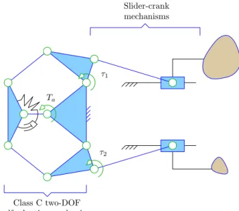
Slider-crank mechanisms Class C two-DOF self-adaptive mechanism τ1 τ2 Ta
Figure 10. A two-DOF self-adaptive linkage driving two slider-crank linkages.
This restriction itself can be lifted with other types of self-adaptive mechanisms, closely related to the principle of con-tinuously variable transmission. The latter is define as a technological solution to compensate a variation in the load driven by an actuator axis. Namely, the ability of a mechan-ical system to continuously change the reduction ratio of its actuator in response to a load variation. These systems are in fact self-adaptive mechanisms too although they have gener-ally only one output, namely the actuator axis. Several mech-anisms have been proposed to achieve this capability, mostly based on gears (Hirose et al., 2004; Ishikawa et al., 2000; Fujushima et al., 2001; Takaki and Omata, 2004) (notice that one of these references is from none other than Prof. Hirose again). This principle has yet to be extended to multi-DOF systems but, provided that the actuation distribution condi-tion is satisfied nothing prevents it. An example of such a mechanism is presented in Fig. 10 where a two-DOF self-adaptive mechanism (the same that was illustrated in Fig. 9) is used to drive two slider-crank linkages. The mechanism is completely symmetrical in order to allow complete revolu-tions of the joints corresponding to τ1and τ2. The actuation
torque is noted Ta. The passive element used here is a spring
in parallel with a damper (the choice is arbitrary) which re-duces the mechanism into a simple Watt’s linkage if τ1= τ2
(neglecting the dynamics of the linkage itself). If the loads of both slider-crank linkages are different as symbolically il-lustrated in Fig. 10, the passive element will accommodate this difference by providing another internal mobility. The transmission linkage will still be distributing the actuation torque to both outputs. This accommodation could then be designed to increase the output torque corresponding to the largest load in order to manage the increased load. This is the
basic principle behind continuously variable transmission as found in the literature. Of course, in this example, it is much simpler to design the system using gears than linkages. 4 Conclusions
As discussed in this paper, the topic of underactuated (or self-adaptive) mechanisms recently attracted a lot of interest from the research community. During the Renaissance, Da Vinci designed a flappin wing that has been centuries later used in an underactuated finge . This example was used to illustrate that self-adaptive mechanisms do not have a single applica-tion and are therefore currently underexploited. The design of ingenious mechanisms is nowadays mainly a lost art due to the ever progressing of electronics. Yet, this skill can be of tremendous interest in modern robotic and mechatronic de-vices. The author strongly believes that the research commu-nity has to put back more focus on the mecha- in mechatron-ics if the best performance are to be obtained or if practical success is required. As a well-known senior researcher once said: kinematics’ not dead (Merlet, 2000)!
Acknowledgements. The fi ancial support of the Natural Sciences and Engineering Research Council of Canada (NSERC) and the Fonds Qu´eb´ecois de la Recherche sur la Nature et les Technologies (FQRNT) is gratefully acknowledged.
Edited by: J. L. Herder
Reviewed by: three anonymous referees
References
Birglen, L.: Type Synthesis of Linkage-Driven Self-Adaptive Fingers, J. Mechanisms Robotics 1, 021010, doi:10.1115/1.3046139, 2009.
Birglen, L. and Gosselin, C.: Geometric Design of Three-Phalanx Underactuated Fingers, ASME Journal of Mechanical Design, 128, 356–364, 2006a.
Birglen, L. and Gosselin, C.: Grasp-State Plane Analysis of Two-Phalanx Underactuated Fingers, Mech. Mach. Theory, 41, 807– 822, 2006b.
Birglen, L. and Gosselin, C.: Force Analysis of Connected Differ-ential Mechanisms: Application to Grasping, Int. J. Robot. Res., 25, 1033–1046, 2006c.
Birglen, L., Lalibert´e, T., and Gosselin, C.: Underactuated Robotic Hands, Springer, New-York, 2008.
Boudreault, E. and Gosselin, C.: Design of sub-centimetre under-actuated compliant grippers, in: 2006 ASME International De-sign Engineering Technical Conferences, Philadephia, PA, USA, 2006.
Carrozza, M. C., Suppo, C., Sebastiani, F., Massa, B., Vecchi, F., Lazzarini, R., Cutkosky, M. R., and Dario, P.: The SPRING Hand: Development of a Self-Adaptive Prosthesis for Restoring Natural Grasping, Auton. Robot., 16, 125–141, 2004.
Crisman, J. D., Kanojia, C., and Zeid, I.: Graspar: A Flexible, Eas-ily Controllable Robotic Hand, IEEE Robot. Autom. Mag., 3(2), 32–38, 1996.
Dollar, A. M. and Howe, R. D.: A Robust Compliant Grasper via Shape Deposition Manufacturing, IEEE-ASME T. Mech., 11, 154–161, 2006.
Doria, M. and Birglen, L.: Design of an Underactuated Compliant Gripper for Surgery Using Nitinol, Journal of Medical Devices, 3, 011007, doi:10.1115/1.3089249, 2009.
Fujushima, E. F., Nakamoto, H., Damoto, R., and Hirose, S.: Opti-mal load-sensitive control for mobile robots equipped with con-tinuously variable transmissions, in: Proceedings of the 2001 IEEE International Conference on Robotics and Automation, Vol. 1, Maui, HI, USA, 476–481, 2001.
Gosselin, C.: Mechanically Intelligent Systems: Smart Designs for High-Performance Robotics, in: Proceedings of the 2005 Cana-dian Congress of Applied Mechanisms, Montreal, Canada, 74– 84, 2005.
Gosselin, C.: Adaptive Robotic Mechanical Systems: A Design Paradigm, ASME J. Mech. Design, 128, 192–198, 2006. Gosselin, C. and Lalibert´e, T.: Underactuated mechanical fin er
with return actuation, US Patent No. 5 762 390, 1996.
Higashimori, M., Kaneko, M., Namiki, A., and Ishikawa, M.: De-sign of the 100G Capturing Robot Based on Dynamic Preshap-ing, Int. J. Robot. Res., 24, 743–753, 2005.
Hirose, S.: Connected Differential Mechanism and its Applications, in: Proceedings of 1985 International Conference on Advanced Robotics, Tokyo, Japan, 319–325, 1985.
Hirose, S. and Umetani, Y.: The Development of Soft Gripper for the Versatile Robot Hand, Mech. Mach. Theory, 13, 351–358, 1978.
Hirose, S., Tibbetts, C., and Hagiwara, T.: Development of X-screw: a load-sensitive actuator incorporating a variable trans-mission, in: Proceedings of the 1999 IEEE International Con-ference on Robotics and Automation, Vol. 1, Detroit, MI, USA, 193–199, 2004.
IFToMM: Terminology for the Theory of Machines and Mecha-nisms, Mech. Mach. Theory, 26, 435–539, 1991.
Ishikawa, Y., Yu, W., Yokoi, H., and Kakazu, Y.: Development of Robot Hands with an Adjustable Power Transmitting Mech-anism, Intelligent Engineering Systems Through Neural Net-works, 10, 631–636, 2000.
Kyberd, P. J., Light, C., Chappel, P. H., Nightingale, J. M., Whatley, D., and Evans, M.: The design of an anthropomorphic prosthetic hands: A study of the Southampton hand, Robotica, 19, 593– 600, 2001.
Lalibert´e, T. and Gosselin, C.: Simulation and Design of Under-actuated Mechanical Hands, Mech. Mach. Theory, 33, 39–57, 1998.
Lalibert´e, T., Birglen, L., and Gosselin, C.: Underactuation in Robotic Grasping Hands, Japanese Journal of Machine Intel-ligence and Robotic Control, Special Issue on Underactuated Robots, 4, 77–87, 2002.
Madangopal, R., Khan, Z. A., and Agrawal, S. K.: Biologically inspired design of small flappin wing air vehicles using Four bar mechanisms and Quasi steady aerodynamics, J. Mech. Design, 127, 809–816, 2004.
Merlet, J.: Kinematics’ not dead!, in: IEEE International Confer-ence on Robotics and Automation, 2000, Proceedings ICRA’00, Vol. 1, 1–6, 2000.
Rovetta, A., Franchetti, I., and Vicentini, P.: Multi-Purpose Me-chanical Hand, US Patent No. 4 351 553, 1982.
12 L. Birglen: From flappin wings to underactuated finger and beyond Rubinger, B., Fulford, P., Gregoris, L., Gosselin, C., and
Lalib-ert´e, T.: Self-Adapting Robotic Auxiliary Hand (SARAH) for SPDM Operations on the International Space Station, in: Pro-ceedings of the 6th International Symposium on Artificia Intel-ligence and Robotics and Automation in Space: i-SAIRAS 2001, Saint-Hubert, QC, Canada, 2001.
Takaki, T. and Omata, T.: Load-Sensitive Continuously Variable Transmission for Robots Hands, in: Proceedings of the 2004 IEEE International Conference on Robotics and Automation, New Orleans, LA, USA, 3391–3396, 2004.
Townsend, W.: The BarrettHand grasper – programmably fl xible part handling and assembly, Ind. Robot, 27, 181–188, 2000. Ulrich, N. T.: Grasping with Mechanical Intelligence, Ph.D.
the-sis, School of Engineering and Applied Sciences, University of Pennsylvania, Philadelphia, Pennsylvania, 1988.