Stainless steel beam-columns in case of fire
N. Lopes, Research Assistant, University of Aveiro, PortugalP. M. M. Vila Real, Professor, University of Aveiro, Portugal L. Simões da Silva, Professor, University of Coimbra, Portugal J.-M. Franssen, Professor, University of Liege, Belgium
Abstract
Eurocode 3 states that stainless steel structural members, subjected to high temperatures, must be designed with the same expressions used on carbon steel
members. However, as these two materials have different constitutive laws, it should be expected that different formulae for the calculation of member stability should be used for room temperature design.
In a recent work, the authors have proposed a more accurate procedure for the evaluation of the fire resistance of stainless steel columns which necessarily affects the beam-column design formulae.
This work presents a numerical study of the behaviour of stainless steel beam-columns subjected to fire.
Introduction
Although some progress has been made in the last years in the knowledge of the behaviour of stainless steel structures at room temperature, fire resistance design has received less attention.
Stainless steel has countless desirable characteristics for a structural material (Estrada, 2005), (Gardner, 2005) and (Euro Inox and SCI, 2006). Even though its use in construction is increasing, it is still necessary to develop the knowledge of its structural behaviour. Stainless steels are known by their non-linear stress-strain relationships with a low proportional stress and an extensive hardening phase. A well defined yield strength does not exist, the conventional limit of elasticity at 0.2% is usually considered.
The EN 1993-1-4 “Supplementary rules for stainless steels” (CEN, 2005a) gives design rules for stainless steel structural members at room temperature, only mentioning fire resistance by reference to the fire part of the Eurocode 3, EN 1993-1-2 (CEN, 2005b). However, as stainless steel exhibits stress-strain relationships different from carbon steel, the formulae used in the determination of structural member resistance in those two materials must be different, as it will be shown in this paper.
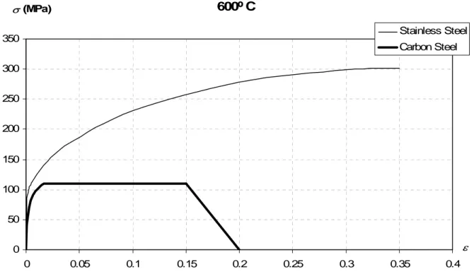
Figure 1 shows the stress-strain relationships of carbon steel S235 and stainless steel 1.4301 (also known as 304) at 600 ºC.
600º C 0 50 100 150 200 250 300 350 0 0.05 0.1 0.15 0.2 0.25 0.3 0.35 0.4 ε σ (MPa) Stainless Steel Carbon Steel
Figure 1: Stress-strain relationships of carbon steel S 235 and stainless steel 1.4301 at 600 ºC. It is the purpose of this paper to evaluate the accuracy and safety of the Eurocode 3 design formulae for the evaluation of the fire resistance of beam-columns. This evaluation was carried out by performing numerical simulations on stainless steel H-columns at high temperature that show that the design buckling resistance formulae are unsafe. The numerical simulations were performed using the program SAFIR (Franssen, 2005), a geometrical and material non linear finite element code, which has been adapted according to the material properties defined in EN 1993-1-4 to model the behaviour of stainless steel structures.
In this paper a brief description of the prescribed formulations in Eurocode 3, for the evaluation of the resistance of stainless steel beam-columns, in case of fire, is presented as well as some proposals for the design of this type of structural members.
Regarding bending and axial compression of stainless steel members at room temperature, section 5.5 in Part 1.4 of Eurocode 3 has two notes written mentioning that the national annexes may give other interaction formulae and other interaction factors, suggesting that the formulae for beam-columns and the interaction factors were not well established for stainless steel members at the time of the conversion from ENV to EN. These formulae for cold design adapted to high temperatures will be tested in this paper.
Two new formulae for the design of carbon steel beam-columns at room temperature are proposed in Part 1.1 of Eurocode 3 (CEN, 2005c), which are the result of the efforts made by two working groups that followed different approaches (Boissonnade et al, 2006), a French-Belgian team and an Austrian-German one. In this paper it will be checked if these two procedures can also be used in stainless steel elements in case of fire.
In the context of Eurocode 3, and under fire loading, Part 1.2 adopts the interaction formulae for beam-columns proposed in the European pre-standard for cold design, ENV 1993-1-1 (CEN, 1992).
Recently, the authors have proposed new formulae for the safety evaluation of stainless steel columns in case of fire (Lopes et al, 2006b), which improves the formulae from Eurocode 3. Its influence on the behaviour of the beam-column design curves will be taken in account here.
Case study
Beam-columns submitted to combined axial compression and uni-axial major and minor uniform moment, have been studied.
The equivalent welded HEA 200 cross-section of the stainless steel grade 1.4301 was used in the numerical simulations. A uniform temperature distribution in the cross-section was used so that comparison between the numerical results and the Eurocode could be made. In this paper, the temperature chosen was 600ºC. Because of the lack of space, only the results for beam-columns with a 3 meter length, will be shown. However several more lengths and slenderness were tested showing the same type of behaviour.
In the numerical simulations, a sinusoidal lateral geometric imperfection was considered (Vila Real and Lopes, 2006). The adopted residual stresses follows the typical pattern for carbon steel welded sections (Chen and Lui, 1985), (Gardner and Nethercot, 2004) and (Greiner et al, 2005), considered constant across the thickness of the web and flanges.
Room temperature
Part 1-1 and Part 1-4 are the parts from Eurocode 3 dedicated to the design of carbon steel and stainless steel structural elements, at room temperature, respectively. In this section a brief description will be made of the methods for cold design of steel elements subjected to combined bending and axial compression.
Eurocode 3 carbon steel interaction curves
Two alternative proposals (Boissonnade et al, 2006) were adopted for the interaction formulae at room temperature (CEN, 2006a) that specifically implement the concepts of amplification factor and equivalent uniform bending moment, namely “method 1” and “method 2”.
The procedure for the determination of the interaction factors for “method 1” is reported in Annex A of Part 1.1 of EC3 and was developed by a French-Belgian team by combining theoretical rules and numerical calibration to account for all the differences between the real model and the theoretical one. “Method 2” is described in Annex B of Part 1.1 of EC3 and results from an Austrian-German proposal that attempted to simplify the verification of the stability of beam-columns, all interaction factors being obtained by means of numerical calibration.
Eurocode 3 stainless steel interaction curves
1 1 , , , , ≤ + M y i pl Ed i i Rd i b Ed f W M k N N γ (1) where, i= yorz, and
(
)
i Rd b Ed i i Rd b Ed i i N N k N N k , , , , 2 2 . 1 2 . 1 but 5 . 0 2 0 . 1 + − ≤ ≤ + = λ (2)It should be pointed out that in the parametric study the possibility of not limiting the factor k to i a minimum value of 1.2 was tested so that the plastic moment could be reached when no axial force is acting, i. e. ki =1.0.
High temperatures
Under fire conditions, the formulae in EN 1993-1-2 (CEN, 2006b) for the design of beam-columns have not changed and are still based on ENV 1993-1-1. These formulae are:
1 , , , , , , , , , , + ≤ fi M y i pl Ed fi i i fi M y y fi i Ed fi f W M k f Ak N γ γ χ θ θ θ (3)
[ ]
2[ ]
2 , 1 θ θ θ φ λ φ χ − + = fi i (4) where( )
[
2]
1 2 1 θ θ θα
λ
λ
φ
= + + (5) and y f / 235 65 . 0 = α (6)The curves obtained with these formulae are denoted “EN 1993-1-2” in figures 2.
In this section a brief description of the methods tested for the design of stainless steel elements subjected to combined bending and axial compression under high temperatures will be made. A previous proposal from the authors (Lopes et al, 2006b), for the evaluation of the fire resistance of stainless steel columns at high temperatures, will be first described and after, all the beam-column procedures tested in this paper will be presented.
Proposal for stainless steel columns
In a previous paper (Lopes et al, 2006b) the authors have made a proposal for the design of stainless steel columns in case of fire. This proposal gives a better approximation to the numerical results and is safer than the formulae from Part 1-2 of Eurocode 3 for the case of welded open sections. This proposal has a direct influence on the beam-column interaction curve.
A new imperfection factor, different from the one used for carbon steel and given in equation (6), has been proposed
y f / 235 4 . 1 = α (7)
As proposed for stainless steel columns at room temperature (Lopes et al, 2006a), it was suggested that in case of fire a factor β with the value of 1.5 should be introduced in the expressions defining the reduction factor χ and the coefficient φ as follows:
2 2 1 θ θ θ φ βλ φ χ − + = fi but χfi≤1 (8)
[
2]
1 2 1 θ θ θ αλ βλ φ = + + (9)Eurocode 3 proposal for carbon steel interaction curves at room temperature adapted for fire situation
(Vila Real et al, 2003) studied the use of the interaction formulae for beam-columns, from Part 1.1 of Eurocode 3 (method 1 and method 2), for fire situation, by modifying all parameters that are usually changed at high temperatures. Here a same approach was adopted using expressions (4) and (8) with the interaction formulae from Part 1.1 of EC3, denoted “Method 1 fi” and “Method 2 fi” or “Method 1 fi NP” and “Method 2 fi NP” respectively, in figure 2.
Eurocode 3 proposal for stainless steel interaction curves at room temperature adapted for fire situation
The formulae, for the beam-column safety evaluation, from Part 1.4 of Eurocode 3 were also tested, but adapted to consider high temperatures. The same approach presented in the previous section has been adopted being the correspondent curves in figure 2 denoted by “prEN 1993-1-4 fi” and “prEN 1993-1-4 fi NP”. In this figure a curve denoted “prEN 1993-1-4 fi NP+NK” is also plotted which corresponds to the relaxation of the minimum limiting value of 1.2 for k in i equation (2).
Eurocode 3 proposal for interaction curves in case of fire
The Eurocode 3 states that the safety evaluation should be made with the same expressions used in carbon steel elements, which are:
1 , , , , , , , , , + ≤ fi M y i pl Ed fi i i Rd fi i b Ed fi f W M k N N γ θ (10) where, i= yorz, and 3 1 , , , , ≤ − = fi M y y fi i Ed fi i i f Ak N k γ χ µ θ (11) and
(
1.2 , −3)
, +0.44 , −0.29≤0.8 = M y y M y y β λ β µ θ (12)(
2 , −5)
, +0.44 , −0.29≤0.8 with , ≤1.1 = β λ θ β λ θ µz M z z M z z (13)Parametric study
Figures 2 show the comparison made at 600 ºC. The interaction curves chosen for this parametric study were obtained using: the Eurocode 3 “EN 1993-1-2”; the Eurocode 3 with the new proposal made for stainless steel columns in case of fire, equations (7), (8) and (9) (Lopes et al , 2006b) “EN 1993-1-2 NP”; the procedure for stainless steel beam-columns at room temperature from Part 1.4 of the Eurocode 3 with and without the new proposal for stainless steel columns “prEN 1993-1-4 fi”, “prEN 1993-1993-1-4 fi NP” and “prEN 1993-1993-1-4 fi NP+NK”. The formulae on Part 1.1 of Eurocode 3 for carbon steel beam-columns with and without the new proposal for stainless steel columns “Method 1 fi” “Method 1 fi NP”, “Method 2 fi” and “Method 2 fi NP” adapted to fire situation, are also plotted in figures 2.
N+My buckling around the y-y-axis L=3000mm; λy,θ =0.360
N+Mz buckling around the z-z-axis L=3000mm; λz,θ =0.584 600 ºC 0 0.2 0.4 0.6 0.8 0 0.2 0.4 0.6 0.8 1 M/Mfi,Rd N/Nfi,Rd SAFIR EN 1993-1-2 EN 1993-1-2 NP a) 600 ºC 0 0.1 0.2 0.3 0.4 0.5 0.6 0.7 0 0.2 0.4 0.6 0.8 1 M/Mfi,Rd N/Nfi,Rd SAFIR EN 1993-1-2 EN 1993-1-2 NP b) 600 ºC 0 0.2 0.4 0.6 0.8 0 0.2 0.4 0.6 0.8 1 M/Mfi,Rd N/Nfi,Rd SAFIR EN 1993-1-2 EN 1993-1-2 NP prEN 1993-1-4 fi prEN 1993-1-4 fi NP prEN 1993-1-4 fi NP+NK c) 600 ºC 0 0.1 0.2 0.3 0.4 0.5 0.6 0.7 0 0.2 0.4 0.6 0.8 1 M/Mfi,Rd N/Nfi,Rd SAFIR EN 1993-1-2 EN 1993-1-2 NP prEN 1993-1-4 fi prEN 1993-1-4 fi NP prEN 1993-1-4 fi NP+NK d)
600 ºC 0 0.2 0.4 0.6 0.8 0 0.2 0.4 0.6 0.8 1 M/Mfi,Rd N/Nfi,Rd SAFIR EN 1993-1-2 EN 1993-1-2 NP Method 1 fi Method 1 fi NP Method 2 fi Method 2 fi NP e) 600 ºC 0 0.1 0.2 0.3 0.4 0.5 0.6 0.7 0 0.2 0.4 0.6 0.8 1 M/Mfi,Rd N/Nfi,Rd SAFIR EN 1993-1-2 EN 1993-1-2 NP Method 1 fi Method 1 fi NP Method 2 fi Method 2 fi NP f) a) and b) Part 1.2 of EC 3 with and without the new proposal for columns; c) and d) Part 1.4 of EC 3 with and without the new proposals, plus a) and b);
e) and f) Part 1.1 of EC 3 for carbon steel with and without the new proposal, plus a) and b). Figure 2: Beam-column interaction curves for a length of 3 meters at 600ºC.
Conclusion
In the case of fire, for bending in the strong axis and buckling around the yy-axis, the curves obtained with the new proposal for columns shows a better approximation to the numerical results. The method that approximates most closely the real behaviour of stainless steel beam-columns under fire conditions is “EN 1993-1-2 NP”. However, for the case of bending around the weak axis there is not a curve that provides a good approximation to the numerical results, which means that new interaction factors should be developed. Nevertheless “EN 1993-1-2 NP” is the only method that provides conservative results.
Acknowledgements
The authors wish to acknowledge the Calouste Gulbenkian Foundation (Portugal) for its supports through the scholarship given to the first author.
References
CEN, European Committee for Standardization, (1992), ENV 1993-1-1, Eurocode 3: Design of steel Structures – Part 1-1: General Rules and Rules for Buildings, Brussels, Belgium. CEN, European Committee for Standardization, (2005a), prEN 1993-1-4, Eurocode 3: Design of steel Structures – Part 1-4: Supplementary Rules for Stainless Steels, Brussels, Belgium.
CEN, European Committee for Standardization, (2005b), EN 1993-1-2, Eurocode 3: Design of steel Structures – Part 1-2: Structural fire design, Brussels, Belgium.
CEN, European Committee for Standardization, (2005c), EN 1993-1-1, Eurocode 3: Design of steel Structures – Part 1-1: General Rules and Rules for Buildings, Brussels, Belgium. Boissonnade N.; Greiner, R.; Jaspart, J.P; Lindner J. (2006), Rules for member stability in EN 1993-1-1. P119 Background documentation and design guidelines, ECCS.
Chen W. F., Lui E. M. (1991). “Stability design of steel frames”; CRC Press.
Euro Inox and SCI, Steel Construction Institute (2006). “Designers Manual for Structural Stainless Steel”.
Franssen, J.-M. (2005), SAFIR. A Thermal/Structural Program Modelling Structures under Fire, Engineering Journal, A.I.S.C., Vol. 42, No. 3, pp. 143-158.
Gardner, L. (2005). “The use of stainless steel in structures”; Progress in Structural Engineering and Materials, 7(2), pp. 45–55.
Gardner, L., Nethercot, D. A. (2004). “Numerical Modelling of Stainless Steel Structural Components—A Consistent Approach”; Journal of Constructional Engineering, ASCE, pp. 1586-1601.
Greiner, R.; Hörmaier, I.; Ofner, R.; Kettler, M., (2005) Buckling behaviour of stainless steel members under bending, ECCS Technical Committee 8 – Stability.
Lopes, N.; Vila Real, P.; Silva, L. (2006a), Numerical modelling of axially loaded stainless steel members, (in portuguese) 4as Jornadas Portuguesas de Engenharia de Estruturas, Lisboa, Portugal.
Lopes, N.; Vila Real, P.; Silva, L.; Franssen, J.-M.; Miranbell, E. (2006b), Numerical modelling of axially loaded stainless steel members under fire conditions, International Colloquium on Stability and Ductility of Steel Structures (SDSS'06), Instituto Superior Técnico, Lisbon.
Estrada, I. (2005). “Shear Design of Stainless Plate Girders”; PhD Thesis, Universitat Politècnica de Catalunya, Barcelona, Spain.
Vila Real, P. M. M., Lopes N., Silva, L., Piloto, P.A.G., Franssen, J.-M. (2003). “Towards a consistent safety format of steel beam-columns: application of the new interaction formulae for ambient temperature to elevated temperatures”; Steel and Composite Structures, techno-press, Vol. 3, No. 6, ISSN 1229-9367 pp. 383-401.
Vila Real, P. M. M., Lopes N. (2006). “New proposals for structural stainless steel fire design”; 4th International Symposium on Steel Structures, Seoul, Korea.