HAL Id: tel-02057982
https://tel.archives-ouvertes.fr/tel-02057982
Submitted on 5 Mar 2019HAL is a multi-disciplinary open access
archive for the deposit and dissemination of sci-entific research documents, whether they are pub-lished or not. The documents may come from teaching and research institutions in France or abroad, or from public or private research centers.
L’archive ouverte pluridisciplinaire HAL, est destinée au dépôt et à la diffusion de documents scientifiques de niveau recherche, publiés ou non, émanant des établissements d’enseignement et de recherche français ou étrangers, des laboratoires publics ou privés.
To cite this version:
Don Joven Agravante. Human-humanoid collaborative object transportation. Micro and nanotech-nologies/Microelectronics. Université Montpellier, 2015. English. �NNT : 2015MONTS224�. �tel-02057982�
D´elivr´e par l’Universit´
e de Montpellier
Pr´epar´ee au sein de l’´ecole doctorale
I2S – Information, Structures, Syst`
emes
Et de l’unit´e de recherche
CNRS-UM LIRMM, IDH, UMR 5506
Sp´ecialit´e:
SYAM – Syst`
emes Automatiques et Micro´
electroniques
Pr´esent´ee par Don Joven Agravante
Human-humanoid
collaborative object
transportation
Soutenue le 16/12/2015 devant le jury compos´e de
Fran¸cois Chaumette DR INRIA, Irisa Rennes Pr´esident Gabriel Abba PU Arts et M´etiers ParisTech Rapporteur Florent Lamiraux DR LAAS-CNRS Rapporteur Pierre-Brice Wieber CR INRIA, Rhone-Alpes Examinateur Andrea Cherubini MCF UM-LIRMM Co-encadrant Abderrahmane Kheddar DR CNRS-AIST Directeur de th`ese
Contents
Acknowledgments iii
List of Symbols v
Introduction 1
1 Background and state-of-the-art 5
1.1 Physical human-robot interaction and collaboration . . . 5
1.1.1 Terminology with a cognitive and behavioral science perspective 5 1.1.2 Robot control for interaction and collaboration . . . 7
1.2 Humanoid robot control . . . 9
1.2.1 Locomotion and walking principles . . . 10
1.2.2 Walking with physical interaction . . . 11
1.3 Human-humanoid collaboration . . . 12
2 Using vision and haptic sensing in physical collaboration 15 2.1 Framework for incorporating vision into haptic joint actions . . . 15
2.1.1 Impedance control . . . 17
2.1.2 Proactive behavior and visual servoing . . . 18
2.1.3 Visual tracking . . . 19
2.2 Case studies . . . 20
2.2.1 Stationary Object - keeping the plane level . . . 20
2.2.2 Moving Object - keeping a ball from falling off . . . 24
2.3 Results and discussion . . . 27
2.3.1 Stationary Object - keeping the plane level . . . 27
2.3.2 Moving Object - keeping a ball from falling off . . . 29
2.3.3 Discussion . . . 31
3 Walking designed for physical collaboration 33 3.1 Dynamic walk model . . . 34
3.2 Walking pattern generator . . . 38
3.2.1 Model Predictive Control . . . 38
3.2.2 Walking as an optimization problem . . . 40
3.2.3 Swing foot trajectories . . . 42
3.3 Specific use cases in physical collaboration . . . 44
3.3.1 Walking pattern generator for a follower robot . . . 44
3.3.2 Walking pattern generator for a leader robot . . . 45
3.4 Simulation tests . . . 47
3.5 Real-robot experiment and results . . . 51
4 Whole-body control for collaborative carrying 55 4.1 A taxonomy of collaborative carrying . . . 55
4.1.1 Agents’ relative pose . . . 57
4.1.2 Grasp types . . . 58
4.1.3 Applying the taxonomy to human-humanoid teams . . . 60
4.2 Decomposing a task into a Finite State Machine . . . 61
4.3 Whole-body control as an optimization problem . . . 64
4.3.1 The base Quadratic Programming formulation . . . 67
4.3.2 Reusable objectives and constraints . . . 69
4.3.3 Formalizing the FSM states as optimization problems . . . 71
4.4 Simulations . . . 73
4.5 Real robot experiments and results . . . 75
Conclusion 79
A Condensing a model predictive control problem 83
Acknowledgments
I would like to thank my thesis advisers Andrea Cherubini and Abderrahmane Kheddar for the guidance and support all throughout this endeavor.
I would also like to thank Gabriel Abba and Florent Lamiraux for taking the time to review this manuscript and to Fran¸cois Chaumette and Pierre-Brice Wieber for examining this thesis. All of your comments, inquiries and suggestions especially during my defense were very much appreciated.
I would also like to express my deep gratitude to the people who have given a tremendous effort in helping me with the various portions of this thesis. To Antoine Bussy for the time and effort to get me started in the field of physical human-robot interaction, to Alexander Sherikov and Pierre-Brice Wieber for collaborating in the conceptualization and development of the walking pattern generators, to Joris Vaillant for sharing his excellent code base on whole-body control and the theoretical and practical discussions on this matter. To all the people who have contributed to this work in some way or another, I am truly indebted to you.
Throughout this undertaking, I had met a lot of great people who shared common experiences, interests, hobbies and humor. To everyone, especially Joris, Alejandro, Ben C., Fran¸cois K., Romain, Antoine, Kevin, Vincent, Ben N., Adrien E., Adrien P., Alfonso, Antonio, Alexander, Damien, Pierre G., Stan, Airi, Tu-Hoa, Gerardo, Herve, Thomas M., Julie, Karim, David, Helene, Marion, Mariam, Thomas G., Celine, Matthias and Mael . Thank you.
To my family and friends from home, I am forever grateful for your unwavering support.
List of Symbols
R is the set of real numbers.
DOF is an acronym for Degrees Of Freedom of a robot. CoM is an acronym for Center of Mass.
MPC is an acronym for Model Predictive Control. ZMP is an acronym for Zero Moment Point.
q ∈ Rn is a vector of joint positions for an n-DOF robot. τ ∈ Rn is a vector of joint torques for an n-DOF robot.
J ∈ Rm×n is a Jacobian matrix for an n-DOF robot where m is the number of task
variables, the classical robot Jacobian has m = 6 with the task defined in 3D Cartesian space.
C ∈ Rn×n is a matrix that relates joint velocities to the vector of Coriolis and centrifugal terms for an n-DOF robot.
H ∈ Rn×n is a symmetric, positive-definite joint-space inertia matrix for an n-DOF robot.
τg ∈ Rn is a vector of torques due to gravity for an n-DOF robot. e ∈ Rm is a vector of m task variables.
x, y, z as superscripts are used to denote the 3 dimensions in Euclidean space. t ∈ R3 is a translation/position vector of an object in a reference frame, for example
at
b = [tx ty tz]⊤ denotes the translation of b in the a reference frame.
θ ∈ Rn is an orientation vector of an object in a reference frame where n denotes the number variables to express an orientation. Examples include Euler angles and quaternions.
R is a rotation matrix of an object in a reference frame, for example aR
b denotes
the rotation of b in the a reference frame.
p ∈ R(3+n) is a generalized pose vector containing both translation and rotation information where n denotes the number variables to express an orientation. T is a generalized transformation matrix which can be used to transform a pose,
motion or wrench to another reference frame, for example aT
b denotes the
transformation of b to the a reference frame. It contains both the rotation and translation (pose) information structured according to the variable being transformed.
f ∈ R3 is a force vector such that f = [fx fy fz]⊤
. n ∈ R3 is a torque vector such that n = [nx ny nz]⊤
. h ∈ R6 is a wrench vector such that h = [f⊤
n⊤
]⊤
.
L ∈ R3 is a vector of the angular momentum such that L = [Lx Ly Lz]⊤
. G is a gain matrix of appropriate dimensions.
m is the mass of an object or virtual model. b is the damping of an object or virtual model. k is the stiffness of an object or virtual model.
x ∈ Rn is a vector of the independent variables to optimize in a mathematical optimization problem where n is the number of variables.
f (x) : Rn → R is an objective function to minimize or maximize in an optimization
problem.
Qqp ∈ Rn×n is a matrix used to define a standard quadratic program’s objective
function where n is the number of variables.
cqp ∈ Rnis a vector used to define a standard quadratic program’s objective function
where n is the number of variables.
w is a weighting parameter to control the relative importance between several ob-jective functions in a mathematical optimization problem.
λ ∈ Rnm is a vector representing the linearized friction cone base weights where n
is the number of contact forces and m is the number of generators chosen to represent the linearization.
Kfc ∈ R3n×nm is a matrix of generators for linearizing the friction cone where n is
the number of contact points and m is the number of generators chosen to represent the linearization such that a concatenated vector of contact forces f = Kfcλ.
List of Symbols vii
n signifies the lower limit of a constraint on variable n in an optimization problem. n signifies the upper limit of a constraint on variable n in an optimization problem.
c ∈ R3 is the position of the Center of Mass (CoM), it is shorthand for tCoM.
z ∈ R3 is the position of the Zero Moment Point (ZMP), it is shorthand for tZMP.
r ∈ R3 is the position of a foot, it is shorthand for tfoot.
ˆ
c ∈ R6 is the state vector of the linear model in the chapter on walking such that ˆ
c= [cx ˙cx c¨x cy ˙cy ¨cy]⊤
.
ˆf ∈ R4 is a particular vector of external forces and torques used for the linear model
in the chapter on walking such that ˆf = [nyext fextx nxext fexty ] ⊤
.
A, B, D, E are matrices used for defining the linear model in the chapter on walking. k as a subscript of the matrices and vectors in the linear model in the chapter on
walking denotes a discrete time interval.
N as a subscript denotes the maximum length of the preview horizon of the MPC. ˜
c ∈ R6N is the state vector of the MPC model in the chapter on walking such that ˜ c= [ˆc⊤ 1 . . . ˆc ⊤ N] ⊤
over an N -step preview horizon. ˜
u ∈ R2N is the control vector of the MPC model in the chapter on walking such that ˜u= [...cx,y⊤0 . . ....cx,y⊤N-1 ]⊤
over an N -step preview horizon.
˜f ∈ R4N is the vector of external wrenches of the MPC model in the chapter on
walking such that ˜f = [ˆf⊤ 1 . . . ˆf
⊤
N]
⊤
over an N -step preview horizon. ˜
z ∈ R2N is the vector of ZMPs of the MPC model in the chapter on walking such that ˜z= [zx,y⊤1 . . . zx,y⊤N ]⊤
over an N -step preview horizon.
Uc, Uu, Oc, Ou, Of are matrices resulting from condensing the Model Predictive
Control Problem in the chapter on walking.
M as a subscript denotes the maximum number of variable footsteps in the preview horizon of the MPC.
˘r ∈ R2Mis the vector of foot landing positions relative to the preceding foot position
such that ˘r= [r0rx,y⊤
1 . . .rM-1r x,y⊤ M ] ⊤ . ˘
z ∈ R2N is the vector of ZMPs relative to the supporting foot/feet such that ˘z = [r1zx,y⊤ 1 . . .rNz x,y⊤ N ] ⊤ .
s are vectors used to concisely describe the MPC states and outputs. vr0 ∈ R
2N is a vector of fixed foot positions used to express the ZMP and variable
foot positions in convenient local frames.
Vr, Vz are matrices containing a certain structure of the foot rotations such that
the ZMP and foot positions can be expressed in convenient local frames.
g ∈ R3 is the acceleration vector due to gravity. ∆t denotes a discrete time step.
Introduction
We live in an amazing time for robotics, with continuous developments coming from various areas. Examples include: self-driving cars being continuously tested and legalized; small unmanned-aerial vehicles (UAVs) operating in several applica-tion areas, including the delivery of goods; collaborative industrial robots, working safely beside humans in manufacturing factories; and the recently concluded DARPA Robotics Challenge (DRC), showcasing several humanoid robots competing in a
real-world scenario. This thesis is a contribution towards the convergence of the last two
areas: humanoid robots with the ability of working together with humans.
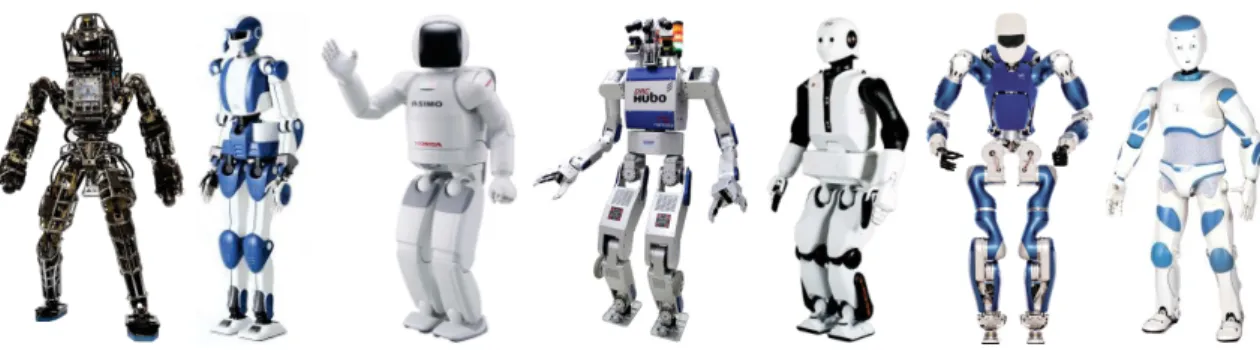
Humanoid robots are robots with an anthropomorphic form. However, this term is often used loosely, since the robot can have varying degrees of similarity with a human. For this thesis, a humanoid is defined as a robot having two legs and two arms, that are attached to a torso with a head, all of which are functional. The functionality of the whole body is the key, since we will be utilizing it throughout this thesis. This definition also implies that humanoids are at the convergence of several robotics research areas: legged locomotion, manipulation control for the arms and hands, sensor processing, just to name a few. Although humanoids have long been conceptualized (especially in science fiction), it was only in recent decades that fully functional humanoids have started to become widespread, with a lot of variation between different classes. Some examples are shown in Fig. 1. The diversity is evident but the similarity in form allows us to be generic in our approach to programming humanoids such as these, which is one of the main goals of this thesis. Although these prototypes are certainly impressive, current day humanoids are still a long way from achieving the functionalities that we desire or envision. Since the form is like, the performance of tasks is similarly expected to be
human-like. Unfortunately, this is not generally the case in the current state of the art.
Typically, most of the robots in Figure 1 are only used within research laboratories, and therefore operate in structured and controlled conditions. A more realistic scenario is that of the DRC, where the winning team required less than 45 minutes for completing a required course, with many teams failing to even complete the first few tasks. Although the performance of the top teams was very impressive by current standards, a human can likely realize the same tasks in under 10 minutes. Clearly, much work is to be done before the general adoption of humanoids will take place.
While the technology for humanoids slowly matured and developed within
Figure 1: Some humanoid robots from recent years, from left to right: Boston Dy-namics’ Atlas, Kawada’s HRP4, Honda’s ASIMO, KAIST’s HUBO, PAL Robotics’ REEM-C, DLR’s TORO, Aldebaran’s Romeo.
search labs, industry has long adapted robots for manufacturing. Many of these specialized, fixed-base robots are big, powerful machines which are designed to be efficient and fast. However, as a consequence, they need to be isolated because of the inherent danger they represent. Oftentimes, these robots require their own workspace or even safety cages. This impedes them from collaborating alongside humans. However, in recent years, there has been a significant emerging branch of industrial robots that brought along a paradigm shift: collaborative robots that are designed to safely work side-by-side with humans. Although these are slow, in comparison to classic industrial robots, they are still efficient and reliable for cer-tain tasks. Furthermore, they are designed to be easily reconfigurable (as opposed to being specialized) for a variety of tasks. Currently, the technology for this has become mature enough, and is starting to be commercialized by several companies, with Fig. 2 showing some examples. Although some companies adopt the single-arm design of classical industrial robots, others have chosen a dual-arm design, in some cases even including a functional head. The design choice of having two arms and a head seems to have stemmed from copying the upper-body humanoid design, or perhaps to help their applicability for working together with humans. Whatever the case may be for the design choice, these robots only need functional legs to be formally called humanoids. However, adding these legs has a lot of implications on how the robot must be controlled and programmed, returning us to the main topic of this thesis: how do we reconnect collaborative and humanoid robotics?
As mentioned, this thesis focuses on collaborative humanoid robots. Although simply described with two words, it is both deep and broad, with the potential to be much more than an industrial tool: it is potentially a general purpose tool in various settings. As it is a broad topic, we begin by giving some background on all the aspects related to collaborative humanoids in Chapter 1. From this, we slowly focus on the main points to be discussed further in the next chapters. Chapter 2 starts with detailing collaboration as it relates to robot control. This eventually leads to utilizing vision and haptics, to enable better collaboration. Chapter 3 then goes into the details on the implications for adding legs to collaborative robots. More
3
Figure 2: Some of the industry-focused, “collaborative” robots, from left to right: KUKA’s LBR-iiwa, Universal Robots’ UR3, ABB’s YuMi, Kawada’s NEXTAGE, Rethink Robotics’ Baxter.
precisely, it details a walking pattern generator designed for physical collaboration. Lastly, Chapter 4 deals with the whole-body control problem. Specifically, the task of collaboratively carrying an object together with a human is broken down and implemented within an optimization framework.
Chapter 1
Background and state-of-the-art
This thesis contributes towards humanoids that can collaborate with humans, ideally with a performance similar to that of another human. This involves several different areas of research. To give some background, Sect. 1.1 starts from physical interaction in general, before going specifically into collaboration. This section also reviews the application of these ideas in robot control, which is our end goal. Next, section 1.2 focuses on the state-of-the-art in humanoid control with a particular view on enabling physical interaction. Finally, section 1.3 reviews the most relevant works on human-humanoid collaboration.
1.1
Physical human-robot interaction and
collab-oration
Physical human-robot interaction (pHRI) is one of the fastest growing research areas in robotics. It is a very broad field, dealing with vastly different aspects, ranging from the human psychology and behavioral science to robot control. This thesis is skewed towards robot control, although the human aspect always needs to be accounted for. Thus, we start with a quick review of some aspects from cognitive and behavioral science in subsection 1.1.1. With this, some important terminology is defined. Afterwards, subsection 1.1.2 gives a more detailed review of robot control for pHRI.
1.1.1
Terminology with a cognitive and behavioral science
perspective
Starting with a cognitive and behavioral science perspective is important to gain some grounding. Since our ideal is to make a robot as effective as a human, a good initial perspective can be obtained by looking at how humans act. The aim is to gain insight into the underlying principles needed to program a robot to successfully collaborate with humans. However, to be clear, the interest is not to do things
exactly as a human would, but rather to take inspiration and try to apply the core concepts into a humanoid robot.
Before going into collaboration in particular, it is useful to start from the more general: interaction. More precisely, we are concerned with physical interaction, since the goal is defined as requiring physical labour. In this thesis, we define physical interaction as the participation of multiple agents (humans and/or robots), jointly, in a given task. Note that simply participating does not imply working together. To clarify this, we adapt the taxonomy of such behaviors from [1]. Although the meanings are kept, we will slightly adapt different terms to better clarify the work targeted in this thesis. The taxonomy of [1] starts by classifying the task. This can be done in two different ways:
1. divisible vs. interactive task, 2. competitive vs. cooperative task.
For the first task taxonomy: a divisible task is such that agents are able to divide the work without fear of conflicts, whereas an interactive task must be done together and at the same time. For example, cleaning a room is divisible but moving heavy furniture (requiring two or more agents) is interactive. Note that divisible tasks can be effectively treated as a collection of independent subtasks. This can be taken ad-vantage of in the context of robot programming, where the subtasks require minimal interaction with the human. In fact, collaborative industrial robots generally target such kind of tasks. On the contrary, this thesis is focused on interactive tasks, that must be done together by humans and robots.
For the second task taxonomy: a competitive task is such that agents work against each other, whereas cooperative tasks require them to work with each other. For example, a tug-of-war game is competitive while pushing a heavy object together is cooperative. This thesis is clearly concerned with cooperative tasks.
Another taxonomy from [1] concerns the behavior of the agents independently from the task. Although the paper defined three general classes with some sub-classes, we firstly simplify this to be:
• competition vs. collaboration.
Note that it is similar to the second task taxonomy. But rather than the nature of the task itself, the agents’ behaviors are highlighted. As for the task taxonomy, we are concerned with making the robot behave in a collaborative manner. Apart from this, the agents may also be classified according to their roles. Studies have shown the importance of specialization of roles in collaborative tasks [2]. Perhaps, the most common role distribution is leader-follower. A leader is defined as the agent having a clear and independent intention for doing the task. Additionally, the leader seeks to guide the follower in doing the task. A follower is the agent, whose intention is dependent on the leader. A follower cannot act on his own to do the task and must be guided by the leader’s intention. However, a follower can be pro-active if
1.1 Physical human-robot interaction and collaboration 7
s/he acts based on a prediction of the leader’s future intention. Contrary to the leader-follower role distribution, an equal-collaboration approach is also possible [3]. Apart from terminology on interaction and collaboration, we can also take in-spiration from how humans function. For example, we can take inin-spiration from studies regarding how humans move, such as [4], or regarding how they use their senses for collaborating. Humans usually use three distinct percepts for communi-cation: sight, touch, and hearing. These factors all play a role in communication during the collaborative task [2]. Additionally, there has been evidence that humans tend to merge these percepts [5, 6] rather than to use them individually.
1.1.2
Robot control for interaction and collaboration
Robot control is a mature field, already being commercialized heavily in industry. However, the principles needed for interacting and collaborating with a human are not yet established and are the subject of a lot of the research in pHRI. One of the main issues is safety. Although there has been a lot of recent push towards this, with a view towards standardization (under the ISO/TC 184/SC 2 for robots and robotic devices [7] for example), we are still in the starting stage before general adaptation. Another of the main issues is the efficiency of the robot, for example its proactivity in following behaviors [8–10]. This issue in particular has tried to draw inspiration from behavioral and cognitive science.
Due to its nature, physical human-robot interaction has largely relied on the use of haptic data (force/torque) for control. By extension, it is grounded in a lot of the core concepts of force control in robotics [11]. In particular, impedance control [12] has been largely adapted with various enhancements. For instance, variable impedance control is used for human-robot collaboration in [13, 14], with parameters obtained from human-human experiments. Similarly, a variable damping controller is defined in [15], using the derivative of the interaction force. A method for improving impedance control, consists in utilizing an estimate of the human’s intended motion [16]. Another possibility is to have a model. For instance, in [8], a minimum jerk model of human motion, inspired from [4], is used to have a good guess of the human intention. This is then used as a desired trajectory within an impedance control framework. Another example is given in [9], where machine learning methods are used to obtain a model of the task, which is then utilized within an adaptive impedance control framework. Conversely, mechanical impedance was shown to be a good model of a human, stabilizing an unstable system [17].
In spite of this important research in haptics, it is clear that vision can provide a lot of complementary information, that cannot be obtained from force/torque sensors alone. For example, information about object motion and human gestures/pose may be acquired. However, the integration of such information into human-robot haptic joint actions is not straightforward. The main issues are: what information would be helpful? how can this information be reliably obtained in the context of the task and platform? and how/where should this information be used? Since the priority
should still be interaction force regulation, the last issue is particularly important and implies the need for combining vision with force data. However, there have not been many applications of this in pHRI. To our knowledge, there has been no previous work on combining vision and force in the context of human-robot haptic joint actions. However, previous works on combining vision and force for object manipulation tasks can be found in the literature. A brief review of these methods follows.
The different approaches to combining vision and force information for manipu-lation tasks can be classified into three general categories [18]. These are: traded, hybrid and shared. The simplest strategy is termed as traded since the final control output is traded between a purely force-based controller and a purely vision-based controller. The switching between controllers depends on the task execution. A common example of this strategy starts by doing a guarded move visual servoing phase. A contact event causes the guarded move phase to stop. After this, the task is completed by force control.
The second category is that of hybrid methods. These are hybrid in the sense that the vision-based controller and force-based controller act at the same time, but in different spaces. This requires prior specification of a task-frame [19–21]. The task frame is a Cartesian reference frame that can be divided into vision-controlled and force-controlled directions. Doing this decouples vision and force into orthogonal spaces. Afterwards, the controllers can be designed separately and work indepen-dently in their own predefined space. The third and final category is termed as
shared methods. These are so-called since there is no separation in time (the case of
traded control) or in space (the case of hybrid control). The control responsibility is shared by both vision and force throughout the operation. By doing this, all available information can be used [18]. An example of a shared method is described in [22], where force feedback is used to correct the visual servo control trajectory.
In the context of human-robot haptic joint actions, a shared method is needed. With the human in the loop, safety is always a top priority. Therefore, the control must always be compliant in all degrees of freedom (DOFs). This can be achieved by always making use of the force information in all DOFs. Therefore, in order to make use of visual data, a shared control strategy must be devised. A good candidate for this is the impedance control framework [12]. Impedance control allows a manipulator to be compliant by defining a virtual mechanical impedance. Vision can be used in this framework to provide a reference trajectory that is tracked in the absence of external forces [23, 24]. When contact does occur, it has the properties of shared control methods, where vision and force determine the control of the same degree of freedom (DOF) simultaneously. This approach is preferred over the others since it can allow for compliance in all DOF. Previous works using this methodology [23–25] presented experiments of a robot interacting with objects. Here, we use this approach for physical human-humanoid collaboration. Having a human as a physical collaborator implies that some issues of this framework are to be revisited, typically the implication of impedance parameters, and the way vision
1.2 Humanoid robot control 9
and haptics are combined in the context of physical collaboration.
Contrary to combining vision and force in control, another possibility is to fuse the different information sources. This can be done with sensor fusion techniques, for example cartesian frames are fused in [26], and fusion of proprioception and vision is done with an extended Kalman filter (EKF) in [27] or with task frame estimation in [28]. These approaches relate back to the merging of percepts by humans in [5, 6]. Although there is some merit to this, inherently there is a re-solvability issue [29]. Force/torque and position/orientation(vision) are inherently different quantities. More formally, motion and force can be represented as dual vector spaces [30]. Another possible usage of vision is in trying to infer/guess the underlying intention behind motion. This concept was explored in [31] for a table-tennis playing robot (also an example of a competitive task). Another example is provided in [32], where the human hand is tracked, with vision, during a hand-over task.
1.2
Humanoid robot control
Humanoid robotics focuses on the design of robots directly inspired by human ca-pabilities. This design gives many advantages when working together with humans in performing tasks. Because of this, humanoids are ideal research platforms for physical Human-Robot Interaction (pHRI). Typically, humans have extensive expe-rience in physically collaborating with each other. Humanoid robots simplify such interactions, since they possess a human-like range of motion and sensing capabili-ties. These can be used to create suitable behaviors, by reducing the need for the human cooperator to learn how to interact with the robot. Although this goal is clear, many challenges are still present in the various research areas.
Among several issues that must be handled for humanoid robots, there are two that make them significantly different from those more commonly found in industry. The first concerns whole-body control. Often, a humanoid robot will have more DOF than an industrial manipulator. This allows several objectives to be realized at the same time. Furthermore, these objectives may have different priorities associated to them. To do this, optimization frameworks have shown to be effective [33–36]. We take this approach and adapt it here to our problem. This is detailed more in chapter 4.
The second differentiator is mobility in the environment. In contrast with fixed-base manipulators, humanoids have the capacity to freely move around. However, this advantage comes at a price since the control must now handle the balance of the robot. This is discussed in detail in the next two subsections, with subsection 1.2.1 giving a short review on the basic principles and terminology of humanoid walking. The main review is given in subsection 1.2.2, which focuses specifically on walking with physical interaction.
1.2.1
Locomotion and walking principles
Locomotion is the process of moving from one place to another. A robot that can ‘locomote’ becomes fundamentally different from the fixed-base robots commonly found in industry. The most obvious difference is the ability to move to different locations by itself. Formally, this ability is described with a floating base [30] that defines the pose of the robot base in a global reference frame. Effectively, it increases the configuration space of the robot. This gives it a significant advantage over fixed base robots. However, this advantage often comes with a drawback. Oftentimes, the floating base is not directly actuated. Therefore, to effectively control the floating base, we must use the contact forces with the environment. This is explained more formally at the beginning of chapter 3. However, if the floating base is not controlled properly, the robot will fall. This is what we want to avoid when locomoting in the environment.
Locomotion is too broad a term, it includes: walking, running, jumping, hopping, crawling, swimming, etc. Among these, walking is the most common and most useful for doing physical collaboration. It has been one of the main subjects of research for humanoid robotics and legged robots in general. A lot of research has been placed into it and there are good reference texts that describe the core principles of robot walking [37, 38]. Before moving into a detailed review on walking related to physical interaction, we shall review some commonly used concepts and terms from the literature.
One of the common methodologies in making robots walk is to start from a
reduced model, instead of directly handling the complexity of the whole-body
dy-namics. A detailed explanation and analysis of the dynamics of the reduced model can be found in [39]. The reduced model is often based on the Center of Mass (CoM). Since contacts are essential in locomotion, the Center of Pressure (CoP) is another important point. However, in the robotics literature, the term Zero-Moment Point (ZMP) is more prevalent. In the normal case, the CoP and ZMP are equivalent [40]. These two points encapsulate the essential dynamics of the system, so that the re-duced model is represented by an equation relating these two. Another important concept related to the ZMP is the support polygon. This is defined as the convex hull of the contact points of the feet on the ground. It defines the area where the ZMP should stay in order for the robot to remain balanced. One of the common benchmark reduced models is the linearized inverted pendulum (LIP) model [41], where the relation is given a physical meaning. A lot of variants to this are the subject of other research. This includes adding a spring to the model to account for energy storage, adding a flywheel to account for angular momentum effects [42], or attempting to generalize the ZMP to non-coplanar contacts [43, 44]. Part of our work is concerned with a reduced model that accounts for physical interaction. Works related to this are mentioned later on.
Apart form the CoM and ZMP, another more recent concept is the capture point [45, 46], which stemmed from capturability analysis. Since having a general
1.2 Humanoid robot control 11
definition of a fall is difficult, capturability seeks to reduce it to being able to come to a stop in a certain number of steps. The capture point can also be shown to be related to the ZMP [38].
With the reduced model, we need to control the robot. This area is also well researched and a widely-recognized benchmark is preview control of the ZMP, with pre-defined future footstep locations [41]. One of the latest improvements on this method is a model predictive control (MPC) approach, with constraints on the ZMP, and variable footsteps that are part of the optimization result [47]. Our current work is based on [47], with the foremost contribution that it accounts for, and uses, physical interaction (i.e. external sustained forces).
1.2.2
Walking with physical interaction
Because of the availability of numerous walking algorithms, some works have tried to take these algorithms as they are and adapt them to more complex scenarios. These works are reviewed here.
In physical collaboration, we can take the example of transporting large or heavy objects together with a human [10, 48–50]. These were done using the methods described in [41, 47]. In these works, the walking pattern generator (WPG) does not take into account physical interaction, which is treated as a disturbance. Since success relies on the robustness of the WPG to this disturbance, an impedance controller is added in the arms, to regulate the interaction forces.
To our knowledge, there have been no works where walking is specifically designed for use in human-humanoid collaboration. The closest to this in the literature takes into account external forces in the WPG model but stops there, effectively treating it as a modeled disturbance instead of a useful signal. Several works do this in demon-strations, where a humanoid robot pushes/pulls objects while walking [43,44,51–57]. All these works present different variations to improve [41], by considering the phys-ical interaction with the object. The work in [52] has an interesting simplification: here, the robot pushes only during the double support phase (when both feet are in contact with the ground), to allow a larger support polygon (and equivalently stability margin) during pushing. To compensate the pushing forces on the hands, the desired ZMP is changed iteratively. However, this causes a discontinuity in the CoM trajectory, so the new CoM trajectory needs to be smoothly connected to the existing one [52]. This also led to research on a generalized ZMP [43, 44]. The work in [51] presents a preview controller of the ZMP, emphasizing short cycle pattern
gen-eration. One of the experiments shows a humanoid pushing a table. This was done
by modifying the desired ZMP to take into account external forces in the ZMP com-putation (compensate a measured disturbance), and moving the torso by the ZMP error (compensating unknown/unmeasurable disturbances). The work in [53, 54] fo-cuses on interacting with known objects, while compensating for unknown effects such as friction. This was demonstrated by pushing a wheelchair and opening cab-inets, doors, etc. Similar to other works, the ZMP computation takes into account
the reaction forces in the hands. Additionally, a footstep modifier was introduced using heuristics from the difference between hand and feet operational points and a ZMP error. Meanwhile, in [55, 56], the main goal is to consider a manipulability criteria for the hands and a balance criteria for the legs. Experiments show the robot pushing a table while walking with varying “resistance” (making it heavier, adding brakes, or with a human at the other end). Again, the ZMP is modified, but this time it also takes into consideration the CoM projection in the support polygon. Furthermore, a theoretical limit on the maximum hand forces is obtained by consid-ering the constraint of ZMP in the support polygon (to retain dynamic balance). Yet another application is in the teleoperation of a humanoid robot [57]. The interface abstracts the WPG, and again the ZMP takes into account the reaction forces in the hands, with the addition of a smoothness term. Furthermore, the unknown force is modeled by a linear damping effect. All these works rely on simplifying assumptions on the interaction wrench applied on the robot, whereas the full wrench is presented and utilized in chapter 3. Additionally, all of these works, except for [51], men-tion the use of impedance/force control on the arms to increase robustness. In [58], the effect of this added impedance control is directly taken into account in model predictive control (MPC), although it is used for postural stability rather than for walking. Another closely related work is [59], which builds on [53, 54] in pushing heavy objects. In particular, the range of allowable external forces is obtained from the model, considering a pre-defined ZMP, as in [41]. Differently from this, the MPC framework presented in this thesis allows to vary both the external forces and ZMP (depending on the objective function weights). Another set of closely related works proposes ‘stepping to maintain balance’ [60–63]. However, these works consider the external wrench as transient, rather than sustained throughout the task.
To summarize, there is not much existing literature on the topic of walking under sustained external forces. A lot of research in walking is validated for abrupt external disturbances, but not for sustained ones. However, in the existing works listed above, these are the common points:
• Although some are presented as whole-body frameworks, the walking task is always abstracted from the hand control tasks, and some type of compensation is done to maintain dynamic balance. That is, the force on the hands is treated as a disturbance to be rejected.
• Most works used a form of compliant control in the contact point (usually the hands) to make sure the net forces are low.
1.3
Human-humanoid collaboration
Probably the best example for interactive, cooperative tasks is the transportation of large and/or heavy objects together. Early work on this topic was done in the Humanoid Robotics Project (HRP), where the HRP-2P humanoid cooperates with
1.3 Human-humanoid collaboration 13
a human for a panel transportation task [48]. This was envisioned to have possible future applications in construction sites. The same scenario can also be applied to the household, such as moving furniture (e.g. table).
Earlier work in this topic involved mobile manipulators [64]. Mobile
manipu-lators use wheels instead of legs for locomotion. The trade-off is having an easier
control (from wheeled robotics technology) over more limited mobility (i.e. requiring drivable terrain). Although the locomotion mode is different, this revealed one of the main issues early on: how to coordinate the motion of the mobile/floating base with the manipulator motion of the upper body. A more recent example of a mobile manipulator doing collaborative carrying is presented in [65].
A similar task has also been tested on smaller scale humanoid robots. For exam-ple in [66], the NAO humanoid was used in collaborative tasks. The main interest is in using other internal sensors in place of force/torque sensors in the hands, which are generally used in the works with full-scale humanoids. NAO is also used in [67], where the capture point is used to guide walking. Another example is Darwin robots collaboratively carrying a stretcher [68]. However here, the human element is removed. And with only robots, the interest is turned to synchronizing the robotic agents.
Within our research group, human-humanoid collaboration has been one of the main topics starting with [69]. One of the foremost contribution of this work is homotopy switching between leader and follower controllers [70]. After this, [71] explored the idea of studying human-human dyads to try and understand how they cooperate for such a task [10]. The main interest was to enhance impedance control with some proactivity. Eventually, some preliminary user studies were also done [71]. This was interesting to see reactions from the common user (i.e. someone not involved with robotics research) and just how applicable such a technology would be in the future. In [49], the idea of role switching and proactivity while turning, is also explored.
From this review on the state-of-the-art in human-humanoid collaboration, we can see that there is a lot of work needed to be done in several different aspects. In particular, this thesis concentrates on 3 main aspects which follow in the cor-responding chapters. Chapter 2 explores the integration of vision with haptics in a collaboration task. Chapter 3 goes into how walking pattern generators can be designed specifically for the expected physical interaction. And finally Chapter 4 shows how we break down the collaborative carrying task starting from a taxonomy of human dyads towards whole-body control with a humanoid robot.
Chapter 2
Using vision and haptic sensing in
physical collaboration
Haptic joint actions are interactive, cooperative tasks, requiring a haptic interaction throughout the task. This applies to several collaborative tasks that humans do together. For example: helping someone to their feet, handing over objects, sup-porting someone while walking, etc. Another common example is carrying a large object together. As haptics is a requirement for all these tasks, most works rely on it to be able to control the robot.
Perhaps the most common example of haptic joint actions is carrying an object together with a robot, such that it has become a benchmark for studying the under-lying principles of physical human-robot collaboration. One of the main principles targeted by research is the allocation of roles between the agents, and specifically how a leader-follower behavior is achieved. This has often been studied with haptics, because of the nature of the task. In this chapter, we reconsider the collaborative carrying task when vision can be used to improve it. Section 2.1 details the frame-work we designed, to add vision to haptics in collaborative tasks. This frameframe-work is applied in the case studies of section 2.2. Section 2.3 concludes the chapter with some results and discussion.
2.1
Framework for incorporating vision into
hap-tic joint actions
Within our research group, there has been a previous focus on physical collaboration using only force/torque sensors [69,71]. These works have led to a good understand-ing of the state-of-the art on programmunderstand-ing humanoid robots to physically collaborate with humans. The focus is a particular example: collaboratively carrying large ob-jects, which has been explored for its practicability and potential applications (e.g. in construction [48]). To improve on these, we first tried to enhance the previous results by adding vision data. Fig. 2.1 illustrates the three important information
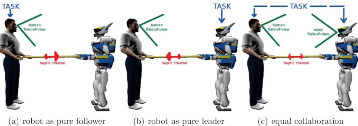
(a) robot as pure follower (b) robot as pure leader (c) equal collaboration
Figure 2.1: Cases of human-robot haptic joint actions
sources to be used: haptic information, visual information and prior task knowl-edge. In this example, the haptic interaction exists through the object - the haptic channel. This means that a force/torque applied on one end of the object is felt by the partner on the other end. Because of this, previous research has focused primarily on regulating interaction forces for safety. The use of vision for the robot has not been investigated before in this context, and is the main focus here. Finally, the prior task knowledge can be used as a guideline on how vision and/or haptic information should be used for the task.
Although what can be achieved using force data alone (i.e., by a blind robot) is impressive, vision is clearly required for some tasks, and could possibly help make the robot proactive. For example, in collaboratively carrying a table, force data alone cannot be used to see if an object on top of the table is about to fall down. It is clear that visual information is largely complementary to force information (analogous to the human senses of sight and touch). Combining these might enable a humanoid to perform more complicated tasks, similar to a human combining these percepts [5].
In the context of role allocation, the most commonly studied scenario of human-robot collaboration consists in making the human-robot a pure follower as in Fig. 2.1(a). This figure illustrates that the task is only known to the human leader a priori. Through the haptic channel, the human communicates his intentions to the robot. With a properly designed controller that takes into account interaction forces, the robot can follow the human’s lead [10]. This is represented by the bigger arrow in the haptic channel from human→robot. Furthermore, the human is able to obtain visual and haptic data as to how good/bad the robot follows the task.
Another situation is the exact opposite of the robot being a pure follower, i.e., it can be the leader of the task. This is illustrated in Fig. 2.1(b). An example of such a scenario is presented in [49], where a joystick is used to give the robot direct information on the task. Although a second human provides this task information via the joystick, in the context of collaborative carrying, the robot is the leader. Without knowing the task of the robot, the human partner then tries to help the
2.1 Framework for incorporating vision into haptic joint actions 17
robot carry the object to a desired location. It is fair to assume that the human uses both the sense of sight and touch to achieve this task. Apart from the two illustrated examples, other possibilities exist. For example, a combined leader-follower strategy has also been developed [3, 70]. The concept for this strategy is that a sharing of roles can be possible where one is both leader and follower (with varying degrees).
Finally, it can be noticed that, in these previous works, the robot is solely re-liant on haptic information. No visual data is used in the task, as illustrated in Fig. 2.1(a,b) by the limitations of the robot field-of-view. The aim of the work here is to move towards the general case of Fig. 2.1(c), particularly adding vision as an-other information channel. In order to do this, the main question is how does one combine vision and force information in the context of haptic joint actions. The context presents significant challenges, specifically by having a human in the loop.
Our general approach to combining vision and haptic cues consists in coupling a visual servoing controller to an impedance controller. This simplifies the design, by decoupling the vision and force controllers in a systematic way. An overview of the complete control framework is shown in Fig. 2.2. Furthermore, it also shows the task example used here - balancing an object on the table. The following subsections explain this general framework in a bottom-up approach starting from the lower level controllers and abstracting it higher to the cognitive level. The lowest level of control is the inner joint-level control. This is represented by q in Fig. 2.2. To abstract from the joint level to the task level, the Stack-of-Tasks framework is used [33]. It is a generalized inverse kinematics abstraction layer that creates a hierarchical organization of different tasks to be executed giving higher priority to critical tasks [33]. It allows for easier integration with sub-tasks. For example, our experiments make use of the walking algorithm in [47] as a sub-task. Later on in this thesis, we go deeper into these two points: namely walking in chapter 3, and
whole body control in chapter 4. For now, the subtasks relevant to this chapter are
explained in the corresponding subsections.
2.1.1
Impedance control
The first sub-task concerns the hands/grippers. In Fig. 2.2 the humanoid uses its grippers to co-manipulate an object with a human. To do this, it needs to be safe and intuitive to use. Here, impedance control [12] is used to regulate the contact interaction (for safety) between the robot and its environment. Impedance control is based on a simple physical analogy to a virtual mass-spring-damper system [12]. This system is governed by the general equation:
h= Gm(¨pdes− ¨p) + Gb( ˙pdes− ˙p) + Gk(pdes− p). (2.1)
The contact interaction is measured by the force-torque sensors in the robot grippers and is represented as h. The vectors pdes, ˙pdes and ¨pdes indicate a desired pose and
its first and second derivatives. Correspondingly, vectors p, ˙p and ¨p represent the corresponding actual pose, and its first and second derivatives. Finally, matrices
Figure 2.2: An illustration of the overall workflow of the algorithms running on the robot to enable collaboration with the human, using both vision and force data.
Gm, Gb and Gk are the inertia, damping and stiffness parameters that define the
desired virtual mass-spring-damper system [12]. Strictly following the terminology and causality from [11, 12], our implementation is an admittance controller, since the robot is position-controlled by the Stack-of-Tasks, which uses the output of p, ˙p and ¨p from the impedance controller. These are obtained by solving the differential equation of Eq. (2.1), given the other variables. The parameters Gm, Gb and Gk are
determined empirically to provide comfort for the human collaborator. The desired pose and trajectory of the mass-spring-damper’s reference position, pdes, pdes, and
¨
pdes, are detailed in the next subsection.
2.1.2
Proactive behavior and visual servoing
For the general impedance controller of Eq. (2.1), a passive behavior is defined by setting the desired pose pdesas constant. This case is illustrated in Fig. 2.1(a) where
only the human knows about the task to be done. This is the classic case in human-robot collaboration. In such a case (and considering constant impedance parameters Gm, Gb, Gk), the robot motion (p, ˙p, ¨p) can only be initiated by an external wrench
h due to Eq. (2.1) . Recent research aims at making the robot a proactive follower, to make the system more comfortable for the human. A way to achieve this is by creating a suitable desired pose and trajectory (pdes, ˙pdes, ¨pdes), such that the human
2.1 Framework for incorporating vision into haptic joint actions 19
effort is minimized [8, 10]. These works differ in the approach taken to produce the desired pose and trajectory. In [8], human motion is predicted by a minimum jerk model to give the desired pose. In [10], a human pair doing a joint transportation task was studied, and it was observed from the data that the pair moves in constant velocity phases during this task. A finite state machine (FSM) is then designed by using the constant velocity assumption, giving the desired pose and trajectory. Haptic cues are used to determine the switching of states in the FSM [10].
We take a different approach here, as illustrated by Fig. 2.1(c). Here, the hu-manoid is given knowledge of the task. This is done by designing a visual servo-ing controller specific to the task and usservo-ing the output as the desired trajectory (pdes, ˙pdes, ¨pdes) of the impedance controller. This also means that the robot has
some autonomy in doing the task, driven by its own knowledge of the state of the task. With the reasonable assumption that, during the collaborative task, human motion is task-driven, the source (human intention to do the task) is taken into account rather than the result (human motion). This differentiates our approach from those that aim to model/predict human motion such as in [8, 10].
Visual servoing consists in controlling robots using visual information [72,73]. To create the visual servoing portion of the framework, two important components are needed: visual feature tracking and a controller based on this feature [72]. However, in the current state-of-the-art, for both modules there is no best approach that fits all tasks and problems. Existing methods have important trade-offs to consider for the whole system [72]. In our works, we take an analytic approach to building the visual servoing portion. These will be detailed for each of the problems in the case studies of section 2.2.
2.1.3
Visual tracking
To start the whole control framework, visual information needs to be processed. In the example depicted in Fig. 2.2, this algorithm gives data about the ball on top of the table. For our case studies, the raw data is a combination of an RGB image and of a depth map, obtained from an RGB-D sensor mounted as the eyes of the humanoid. This raw data needs to be processed into an estimate of the pose or position to be controlled by the vision-based controller. This is done by tracking a salient visual feature throughout the image sequence, and extracting the needed pose or position information from this. Although there is not yet any generic visual tracking algorithm that can work for any and all cases, well-known computer vision methods from reference texts, such as [74–76], may be used to obtain this information, given some simplifications. Furthermore, some knowledge of the task is needed to know what is the important visual information that is needed. This is the reason why the case studies presented here use trivial objects - a cube of known size and color, and a ball of known color. Although far from generic, visual tracking is a fairly well-developed field in computer vision, and a wide range of algorithms have been developed, as reported in this extensive survey [77]. Similar to visual servoing,
the vision algorithm, applied in each of our case studies, is detailed in section 2.2.
2.2
Case studies
To test the framework described, we tackle two case studies of human-robot haptic joint actions, that clearly benefit from visual information. Because the task of
collaborative table-carrying has been well-studied within our research group, this
is used as the base task. An object is then placed on top of the table and the additional task is concerned with this object, and with the table tilt angles (φx, φy).
A simplified side-view of the task in Fig. 2.3 shows φy and its relation to the height
difference zr, and to the table length lt. Furthermore, three important reference
frames are drawn in this image, to facilitate the explanations that follow. These are: the control frame {cf}, a local reference frame on the robot {l} and the table frame {t}. The control for the robot can be done just by defining the pose lT
cf. This is
justified by assuming a rigid grasp during the whole task. This means that the pose of the right and left hands: cfT
rh and cfTlh are constant throughout the task, and
generating the 2-handed control merely consists in a change of frame. To achieve this, the hand poses {rh} and {lh} are controlled in the local frame according to:
lT
hand =lTcfcfThand hand = {rh, lh}.
Z
rt
{ }
cf
{ }
l
{ }}}
φ
yt
{ }
cf
c
{
f
}
}
l
tFigure 2.3: A simplified “thin beam” model, used to control the table tilt, through the height offset between robot and human grasps.
2.2.1
Stationary Object - keeping the plane level
In this scenario, a green cube is placed on top of the table as a representative
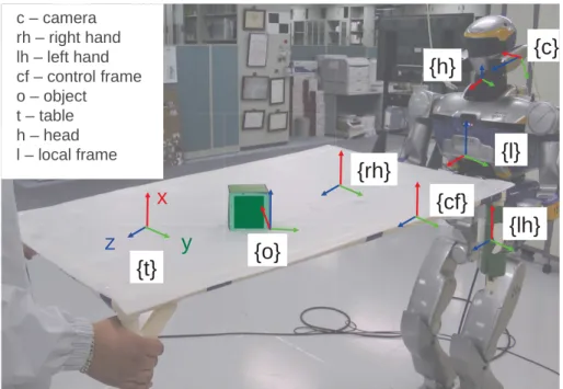
stationary object. This scenario, along with the important reference frames, is shown
2.2 Case studies 21
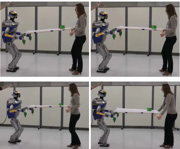
Figure 2.4: Case 1: table carrying scenario with stationary object.
With the simplified model of Fig. 2.3, vision is used to estimate φy – the
inclina-tion of the table. This is used as an error signal for a table height controller, to be detailed later. For this particular case, we only use the RGB data (not the depth) from the camera mounted on the humanoid robot head. Because of the viewpoint, φy cannot be directly observed on images taken from the robot, and must be
ex-tracted from 3D data. Although a variety of ways to extract this 3D data exist, a fast visual tracker is preferred here.
Visual tracking is used to obtain the pose of an object, of a priori known model, resting on the table (e.g., the cube of Fig. 2.4, with frame {o} linked to it). The pose is represented by the homogeneous transformation matrix cT
o, where the camera
frame {c} is the reference. Frame {o} is defined, so that its z-axis corresponds to the vector normal to the table/beam (see Fig. 2.4 and 2.3). This vector forms angle φy with the z-axis of frame {l}. To obtain the transform, a virtual visual servoing
approach is used here for tracking and pose estimation [78]. This method relies on a model-based edge tracker, and is available as part of the visual servoing software library – ViSP [79]. It works by first initializing the projection of the object model onto the image. The edges are then tracked throughout the image, and a robust optimization process is used to obtain cT
o from fitting the tracked edges onto the
model [78]. A visualization of a typical result (cT
o) is shown in Fig. 2.5 (left and
middle images). Figure 2.5 also shows, in the rightmost image, how edges are tracked in the normal direction [78].
Reliability can be an issue for visual tracking and even state-of-the-art algorithms can fail [77]. This uncertainty is a problem, especially if the visual tracker output
Figure 2.5: Typical result of the visual tracker. The full image is at the left. The middle image is a zoomed-in portion bordered by blue, with the projection of the cube’s model in red, and the object frame in green. The right image shows how edges are tracked.
is to be used for control. Therefore, precautions are taken here to prevent this. A known platform-specific problem in humanoid robots is the motion induced by walking. The effect on the image is a characteristic oscillatory motion [80, 81]. Furthermore, impact forces resulting from the walk can cause significant blur on some images. These problems make it necessary to add robustness to the tracker.
Although it is possible to model the cause of these problems (walking) and com-pensate for it directly [80,81], a more general approach is taken here to handle other unforeseen disturbances. More specifically, a fault detection and tracker reinitial-ization process is implemented. This method is also advocated in [77] as a possible future trend, since all trackers can fail given a difficult enough condition.
The first requirement is the ability to detect a fault. The covariance matrix of the tracker optimization process is used as a measure of goodness. A fault condition arises if var > thr where var is the variance vector (diagonal elements of the covariance matrix) and thr is a threshold vector that is manually tuned off-line by observing the tracker results from a typical image dataset. When one or more of the vector values is at fault, the tracker is reinitialized.
The next requirement is a reinitialization procedure using a good guess of cT o.
The reinitialization itself is trivial, and a method is already provided in ViSP. The main problem is estimating cT
o. A tracker failure often indicates that the
assump-tion of continuity between images is invalid. Therefore, the data for reinitializaassump-tion must come mainly from the current image. Another important consideration is the runtime. Obtaining a guess forcT
oshould be fast enough, so that continuity towards
the next images can be safely assumed. Therefore, speed is chosen over generality. To start, the object needs to be detected in the current image. This is done quickly, by thresholding and applying a sliding window for optimal detection. For thresholding, the hue space is used because the object used in this work has a distinct color. To speed up sliding window detection, the concept of image-pyramids is used, with coarse detection in a smaller scale version of the image. The result is used for
2.2 Case studies 23
successively finer detections up to the original image size. This results in a good localization in image space I(x, y) where x and y are normalized image locations
such that: x = cX o cZ o y = cY o cZ o , withc(X, Y, Z)
o the Cartesian coordinates of the object {o} in the camera frame {c}
(see Fig. 2.4). A correct pose at the previous iteration t − ∆t (∆t is the control time step) can be used as a guess for the object orientation cRt−∆t
o and depthcZot−∆t, so
that the new pose, at the current iteration t, is defined as:
ctt o = xt ·cZt−∆t o yt·cZt−∆t o cZt−∆t o cRto=cRt−∆to .
Although this new pose is imperfect, it is a good guess for reinitializing the tracker. Furthermore, the assumptions used here fit with the table carrying task done by a humanoid robot, namely: the depth to the objectcZ
o is fairly constant, the rotation
of the object is minimal, and most of the perturbation from walking results in a perturbation in image space I(x, y).
Lastly, another covariance check is done after the tracker is reinitialized. In the event that even the reinitialization fails, a failure signal is produced such that the visual servo controller also stops, thus preventing erroneous motions. This is more of a safety measure, since the tracker reinitialization worked well throughout the experiments.
Referring back to Fig. 2.3, φy is defined using {l} as the reference. However,
visual data gives cT
o, and as such a change of frame is needed:
lT
o=lThhTccTo. (2.2)
hT
c is the pose of the camera in the robot’s head frame. It is a constant matrix
obtained from an off-line camera-robot calibration procedure. The pose of {h} in the local frame (lT
h) is available from proprioception. The angle φy can then be
extracted from the rotation matrix of lT
o, i.e., lRo, by
φy = arctan(−R13, R33), (2.3)
where Rab is the element at row a column b of lRo. Eq.(2.3) is obtained from the
relationship between axes that a rotation matrix represents. The z-axis of {o} is the column vector where b = 3, since {l} is the reference, the important components are in the x-axis (a = 1) and z-axis (a = 3). The final result φy, is only dependent
on the rotations of Eq. (2.2) and the program implementation can be optimized as such. Furthermore, only results where −π
2 < φy < π
2 are considered valid. The limits
correspond to the table being fully vertical and provide a safety measure.
Visual servoing enables the direct use of visual information in the controllers. To start the design, the error e needs to be defined. Fig. 2.3 shows that φy, the angle
between the table normal and the vertical is suitable such that: e = φy− φ ∗
y, where
φ∗
y denotes the desired value of φy. Defining a task that keeps the table horizontal
implies that the desired value φ∗
y = 0 making e = φy. The model of the task can be
defined as:
ltsin φy = Zr (2.4)
Eq. (2.4) relates the observed angle φy to the height difference (Zr) and the table
length (lt). Differentiating with respect to time and rearranging the terms results
in: ˙ φy = ˙ Zr ltcos φy (2.5)
Eq. (2.5) is the model of the system and the controller can be derived from this. If, for example, an exponential decrease of the error is desired, it must be ˙e = ˙φy = −λφy. Since the table length lt is constant, it can be considered as part of
the gain parameter λ. The control law then becomes: ˙
Zr = −λ ˆφycos ˆφy, (2.6)
where ˆφy represents the estimate of φy. If the estimation is perfect ( ˆφy = φy),
plugging (2.6) into (2.5) yields: ˙φy = −λltφy. This shows that lt contributes only to
the convergence speed, and as mentioned it is not necessary to know its value. It only affects the tuning of the gain λ.
To use this result in the impedance control framework, ˙Zr is numerically
inte-grated such that Zr at the current digital time step is obtained as: Zrt = Zrt−∆t +
˙ Zt
r∆t. Lastly, a constant velocity is assumed throughout the time step such that
¨
Zr = 0. The results here (Zr, ˙Zr, ¨Zr) are then used as the Z part of pdes, ˙pdes, ¨pdes in
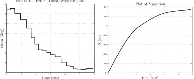
the impedance controller, taking into account the difference in reference frame (i.e. {l} and {cf}). The results of this are shown in section 2.3.
2.2.2
Moving Object - keeping a ball from falling off
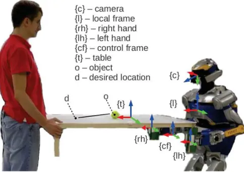
In this scenario, a ball is placed on top of the table as seen in Fig. 2.6. Any distur-bance will tend to make the ball fall off the table. As in the previous case, two main components are needed: visual tracking and the control design which are detailed as follows.
This time, both RGB and depth data from the camera are used. The aim of the vision algorithm is to process this raw data into visual features that can be used for control. An error signal can be defined by tx
o−txd and tyo−tyd. For the
example task here, z is irrelevant, sincetz
d≡tzo. Since the desired location t(x, y)d
is arbitrarily defined, the vision algorithm only needs to obtaint(x, y)
o. A variety of
vision algorithms that can do this may be used, with speed as another consideration. For example, given the object model and the table model, it is possible to use a model based tracker, similar to the other case study. Designing a novel vision algorithm is
2.2 Case studies 25
Figure 2.6: Case 2: table carrying with moving object
not the focus of this work, so we use well-known methods [74–76]. Nevertheless, the methods used here are briefly described for completeness.
The features used here are the centroids of the object and that of the table. The first step is to segment these from the image. Color segmentation is used in our system. The ball has a known color, and it can be easily characterized and thresholded by a specific hue range and a high saturation (from the HSV color space). To add robustness, morphological operations (opening and closing) are used to remove outliers. After this, sliding window detection (sped up using the image pyramids concept) finds the most probable location of the ball. The centroid of the detected blob (corresponding to the ball) is denoted with (u, v) in pixel coordinates. This is then converted into cx
o and cyo by using the intrinsic camera calibration
parameters (fx, fy, cx, cy) and the depth czo as follows:
cx o = cz o(u−cx) fx , cy o = cz o(v−cy) fy . (2.7)
The next step is to segment the table in the image. A flood fill algorithm [76] is run in saturation-value-depth space. This algorithm starts with a seed point and grows the region based on a connectivity criterion between neighboring pixels. Here, the seed point is the bottom pixel of the ball. A low saturation and high value characterize well the white color of the table. The addition of depth ensures connectivity in Cartesian space, simplifying for example the segmentation between table and floor pixels. Finally, some morphological operations (opening and closing) are done to remove outliers. From these segmented points, the Cartesian centroid is used as ct
t