HAL Id: hal-01433996
https://hal.inria.fr/hal-01433996
Submitted on 13 Jan 2017
HAL is a multi-disciplinary open access
archive for the deposit and dissemination of
sci-entific research documents, whether they are
pub-lished or not. The documents may come from
teaching and research institutions in France or
L’archive ouverte pluridisciplinaire HAL, est
destinée au dépôt et à la diffusion de documents
scientifiques de niveau recherche, publiés ou non,
émanant des établissements d’enseignement et de
recherche français ou étrangers, des laboratoires
Mouloud Ourak, Brahim Tamadazte, Nicolas Andreff, Eric Marchand
To cite this version:
Mouloud Ourak, Brahim Tamadazte, Nicolas Andreff, Eric Marchand. Multimodal Image Registration
and Visual Servoing. Lecture Notes in Electrical Engineering, 383, Springer, pp.157 - 175, 2016,
�10.1007/978-3-319-31898-1_9�. �hal-01433996�
UNCORRECTED PROOF
Servoing
M. Ourak, B. Tamadazte, N. Andreff and E. Marchand
Abstract This paper deals with multimodal imaging in the surgical robotics context.
1
On the first hand, it addresses numerical registration of a preoperative image obtained
2
by fluorescence with an intraoperative image grabbed by a conventional white-light
3
endoscope. This registration involves displacement and rotation in the image plane as
4
well as a scale factor. On the second hand, a method is developed to visually servo the
5
endoscope to the preoperative imaging location. Both methods are original and dually
6
based on the use of mutual information between a pair of fluorescence and white-light
7
images and of a modified Nelder-Mead simplex algorithm. Numerical registration is
8
validated on real images whereas visual servoing is validated experimentally in two
9
set-ups: a planar microrobotic platform and a 6DOF parallel robot.
10
1 Introduction
11
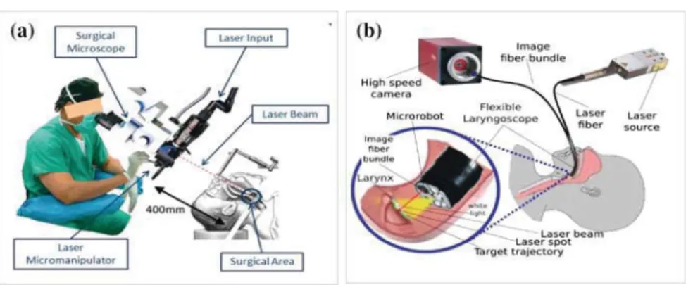
This work is grounded into robot assisted laser phonosurgery (RALP). The current
12
gold standard procedure for the vocal folds surgery is certainly suspension
micro-13
laryngoscopy (Fig. 1a) which requires direct visualization of the larynx and the
14
trachea as proposed in [9]. This system is widely deployed in hospitals but it features
15
many drawbacks related to patient and staff safety and comfort. Therefore,
alterna-16
tive endoscopic approaches are under investigation: the extended use of the HARP
17
(Highly Articulated Robotic Probe) highly flexible robot, designed for conventional
18
surgery [6] or the use of an endoscopic laser micro-manipulator [17] (Fig.1b). In
19
all aforementioned cases, cancer diagnosis can be performed thanks to fluorescence
M. Ourak (
B
)· B. Tamadazte · N. AndreffFEMTO-ST Institute, AS2M Department, Université Bourgogne Franche-Comté/CNRS/ENSMM, 24 Rue Savary, 25000 Besançon, France e-mail: [email protected]
E. Marchand
Université de Rennes 1, IRISA, Rennes, France
© Springer International Publishing Switzerland 2016
J. Filipe et al. (eds.), Informatics in Control, Automation and Robotics 12th International Conference, ICINCO 2015 Colmar, France, July 21-23, 2015 Revised Selected Papers, Lecture Notes in Electrical Engineering 383, DOI 10.1007/978-3-319-31898-1_9
1
UNCORRECTED PROOF
Fig. 1 Global view of the microphonosurgery system: a the current laser microphonosurgery system
and b the targeted final system
imaging [16], (a few) days before the surgical intervention. The latter is usually
20
performed under white-light conditions because fluorescence may require longer
21
exposure time than real time can allow. Therefore, during a surgical intervention the
22
fluorescence diagnosis image must be registered to the real-time white light images
23
grabbed by the endoscopic system in order to define the incision path of the laser
24
ablation or resection. Registration can be done either numerically or by physically
25
servoing the endoscope to the place where the preoperative fluorescence image was
26
grabbed.
27
In this paper, our aim is to control a robot based on direct visual servoing, i.e.
28
using image information coming from white light and fluorescence sensors. Several
29
visual servoing approaches based on the use of features (line, Region of interest
30
(ROI)) [2] or the image global information (gradient [11], photometry [3] or mutual
31
information [5]) can be used. Nevertheless, the use of mutual information (MI)
32
in visual servoing problems has proved to be especially effective in the case of
33
multimodal and less contrasted images [4]. In fact, these control techniques assume
34
that the kinematic model of the robot and the camera intrinsic parameters are at
35
least partially known, but would fail if the system parameters were fully unknown.
36
In practice, the initial position cannot be very distant from the desired position to
37
ensure convergence. To enlarge the stability domain, [12] proposed to use the Simplex
38
method [13] instead of the usual gradient-like methods (which require at least a rough
39
calibration of the camera and a computation of the camera/robot transformation).
40
However, the work in [12] relies on the extraction from the image of geometrical
41
visual features.
42
Furthermore, in the surgical robotics context, it is preferable to free ourselves
43
from any calibration procedure (camera, robot or robot/camera system) for several
44
reasons:
45
1. Calibration procedures are often difficult to perform, especially by
non-46
specialist operators i.e., clinicians.
47
UNCORRECTED PROOF
2. Surgeons entering in the operating room are perfectly sterilized to avoid any risk
48
of contamination, and then it is highly recommended to limit the manipulation of
49
the different devices inside the operating room.
50
For these reasons, we opted for uncalibrated and model-free multimodal registration
51
and visual servoing schemes using mutual information as a global visual feature and
52
a Simplex as optimization approach. Thereby, it is not necessary to compute the
53
interaction matrix (Jacobian image); the kinematic model of the robot may be totally
54
unknown, without any constraint in the initial position of the robot with respect to its
55
desired position. A preliminary version of this work was presented in [14] in the case
56
of planar positioning and is extended in this paper to positioning in the 3D space.
57
This paper is structured as follows: Sect.2 explains the medical application of
58
the proposed approach. Section3gives the basic background on mutual information.
59
Section4presents a modified Simplex method. Section5describes multimodal
reg-60
istration and multimodal visual servoing. Finally, Sect.6 deals with the validation
61
results.
62
2 Medical Application
63
The vocal folds are situated at the center and across the larynx and form a V-shaped
64
structure. They are used to create the phonation by modulating the air flow being
65
expelled from the lungs through quasi-periodic vibrations. They can be affected by
66
benign lesions, such as cysts or nodules (for instance, when they are highly stressed,
67
e.g. when singing) or, in the worst case, cancer tumors (especially for smokers). These
68
lesions change the configuration of the folds and thereby the patient’s voice.
Nowa-69
days, medical tools can be used to suppress this trouble and recover the original voice
70
in particular for cyst and nodules. Appeared in 1960, phonosurgery—the surgery of
71
the vocal folds—can be divided into laryngoplastic, laryngeal injection, renovation
72
of the larynx and phonomicrosurgery. Specifically, laser phonomicrosurgery
con-73
sists of a straight rigid laryngoscope, a stereoscopic microscope, a laser source, and
74
a controlled 2DOF device to orient the laser beam [8], as shown in Fig.1a.
Nev-75
ertheless, the current system requires extreme skill from the clinician. Specifically,
76
high dexterity is required because both the laser source is located out of the patient,
77
400 mm away from the vocal folds. This distance increases the risk of inaccuracy
78
when the laser cutting process is running. Moreover, the uncomfortable position of
79
the patient’s neck in a straight position all along the operation can be traumatic. The
80
drawbacks of the conventional procedure are taken into account in the new set-up
81
developed within the European project µRALP, which consists on embedding all the
82
elements (i.e., cameras, laser and guided mirror) inside an endoscope Fig.1b. More
83
precisely, the endoscope is composed of white light, high speed camera imaging
84
the laser evolution with 3D feedback to the clinician. Additionally, a low framerate,
85
high sensitivity fluorescence imaging system is to be used preoperatively to detect
86
cancerous lesions.
87
UNCORRECTED PROOF
The global approach is based on the use of 2 degrees of freedom (DOF) to guide the
88
laser along the trajectory drawn by the surgeon on a preoperative fluorescence image.
89
However, since the preoperative image is not necessarily taken by the same
instru-90
ment on the same location, this approach requires the preoperative fluorescence
91
image (where the surgeon decides the trajectory) and the white light image (where
92
the control of the robot is developed) to be registered. This can be done in two ways:
93
registration or servoing. Registration deals with the estimation of the transformation
94
between both images, which can then be used to morph the fluorescence image onto
95
the real-time endoscopic image flow (for instance, as an augmented reality). Visual
96
servoing deals with bringing the endoscope back to the place where the fluorescence
97
image was grabbed and stabilizing it in that configuration, which amounts to a
phys-98
ical registration and should turn useful in many other applications, such as surgery
99
in the stomach to compensate for physiological motions.
100
3 Mutual Information and Registration
101
In the literature, multimodal image registration has been widely discussed. Zitova
102
et al. [19] classified registration techniques for medical applications into two main
103
categories: area-based and features-based methods. In these cases, the registration
104
process follows mainly four steps: feature detection, feature matching,
transforma-105
tion estimation, and image resampling. As previously stated, our approach is based
106
on mutual information rather than geometrical visual features. Therefore, the most
107
critical steps (feature detection and matching) of a conventional registration method
108
are removed. Instead, from the joint and marginal entropy of two images, it is
possi-109
ble to compute their similarities. This means that the higher the mutual information
110
is, the better the images are aligned [4] (Fig.2).
AQ1111
Fig. 2 Vocal folds endoscopic images: a white light endoscopic image, b fluorescence endoscopic
image [18]
UNCORRECTED PROOF
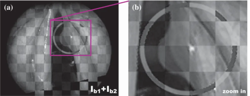
3.1 Mutual Information in the Image
112
Mutual information is based on the measure of information, commonly called entropy
113
in 1D signal. By extension, the entropy expression in an image I is given by
114 H(I) = − NI ! i=0 pI(i)log2(pI(i)) (1) 115
where H(I) represents the marginal entropy, also called Shannon entropy of an image
116
I; i ∈ [0, NI] (with NI = 255) defines a possible gray value of an image pixel; and
117
pIis the probability distribution function, also called marginal probability of i. This
118
can be estimated using the normalized histogram of I.
119
Moreover, the entropy between two images I1 and I2is known as joint entropy
120
H(I1,I2). It is defined as the joint variability of both images
121 H(I1,I2)= − NI1 ! i=0 NI2 ! j=0 pI1I2(i, j)log2(pI1I2(i, j)) (2) 122
where i and j are the pixel intensities of the two images I1 and I2 respectively;
123
and pI1I2(i, j) is the joint probability for each pixel value. The joint probability 124
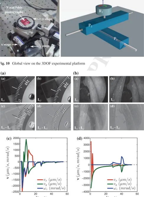
is accessible by computing the (NI1+ 1) × (NI2+ 1) × (Nbin+ 1) joint histogram 125
which is built with two axes defining the bin-size representation of the image gray
126
levels and an axis defining the number of occurrences between I1and I2.
127
From (1) and (2), the mutual information contained in I1and I2is defined as
128
MI(I1,I2)= H(I1)+ H(I2)− H(I1,I2) (3)
129
and can be expressed using the marginal probability pI and joint probability
130
pI1I2(i, j), by replacing (1) and (2) in (3) with some mathematical manipulations 131 MI(I1,I2)= ! i, j pI1,I2(i, j)log " prI1I2(i, j) pI1(i) pI2(j) # (4) 132
This cost-function has to be maximized if I1and I2are requested to “look like each
133
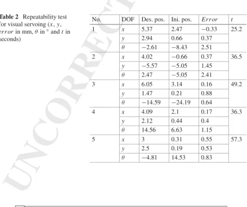
other”.
134
In practice, the cost-function computed using (4) is not very smooth. This creates
135
local maxima, hence complicating the convergence optimization process [4]. To
136
reduce the joint histogram space as well as the irregularities in the mutual information,
137
and thereby local maxima (at least for the less significant ones), Dawson et al. [7]
138
proposed to use the in-Parzen windowing formulation when computing the mutual
139 information: 140 Ib1(k)= I1(k)rNmaxc and Ib2(k)= I2(k) Nc tmax (5) 141 Author Proof
UNCORRECTED PROOF
where tmax = rmax = 255 and Nc are the new bin-size of the joint histogram and
142
Ib1,Ib2are the new gray level value of I1and I2, respectively.
143
In addition to re-sampling of the joint histogram, it is advisable to introduce
144
a filtering method based on B-splines interpolation in order to further smooth the
145
mutual information cost-function. As far as multimodal images are concern, the
146
abrupt change in the cost-function creating local maxima are flattened in order to
147
reduce again these irregularities. In practice, we opted for a third-order interpolation
148
ψ, which presents a good balance between smoothing quality and time computation.
149
Thereby, both marginal and joint probabilities become
150 pIb1Ib2(i, j)= 1 Nk ! k ψ (i− Ib1(k)) ψ"j− Ib2(k)# (6) 151 pIb1(i)= 1 Nk ! k ψ (i− Ib1(k, x)) (7) 152 pIb2(j)= 1 Nk ! k ψ ( j− Ib2(k)) (8) 153 154
with Nk is the number of pixels in the new images Ib1 and Ib2 and ψ is the used
155
B-spline function.
156
4 Simplex-Based Registration
157
This section deals with the method for solving the mutual information maximization
158
problem. However, before describing the chosen optimization approach among the
159
many existing ones [10] to solve this problem, it is necessary to know the exact shape
160
of the cost-function in the case of bimodal images (fluorescence vs. white light) of
161
the vocal cords.
162
In practice, rather than maximizing mutual information, we minimize the
cost-163
function
164
f(r) = −MI[Ib1(r), Ib2] (9)
165
In the general case, because the mutual information depends on a Euclidean
166
displacement (i.e. in SE(3)) between both image viewpoints, the problem to solve is
167
$r = arg min
r∈SE(3)f(r) (10)
168
where r is the camera pose with respect to the world reference frame, attached to the
169
fluorescence image.
170
UNCORRECTED PROOF
Fig. 3 MI cost-function in nominal conditions (representation of -MI) 0 10 20 30 0 5 10 15 −0.5 −0.45 −0.4 −0.35 −0.3 −0.25 −0.2 −0.15 x−displacement (mm) y−displacement (mm) Cost4.1 Cost-Function Shape
171Figure3shows the computed cost-function in nominal conditions (i.e., the high
def-172
inition images shown in Fig.8). It has a global convex shape but still has many
173
irregularities. Consequently, derivative based methods such as gradient descent could
174
not necessarily guarantee convergence. Thereby, an unconstrained optimization
tech-175
nique was chosen to overcome this problem, i.e., a modified Simplex algorithm.
176
4.2 Modified Simplex Algorithm
177
The Nelder-Mead Simplex algorithm [13] roughly works as follows. A Simplex
178
shape S defined by vertices r1 to rk+1 with k= dim(6) is iteratively updated until
179
convergence using four operators: reflection, contraction, expansion, and shrinkage
180
(see Fig.4), defined on a linear space.
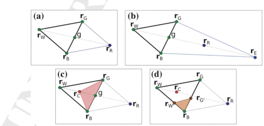
181
(a) (b)
(c) (d)
Fig. 4 Example of the Simplex steps: a reflection, b expansion, c contraction, and d shrinkage
UNCORRECTED PROOF
In order to apply this algorithm in the non linear Euclidean space, we represent
182
any rigid displacement r∈ SE(3) as
183 r = % t uθ & such that [r]de f= % [u]∧ t 01×30 & de f = logmT (11) 184
where logm is the matrix logarithm and T is the 4× 4 homogeneous matrix
repre-185
sentation of r.
186
Thus, the usual four steps of the Simplex S can be used:
187
reflection: rR = (1 − α)g + αrW (12)
188
where rRis the reflection vertex, α is the reflection coefficient and g is the centroid
189
between rGand rB.
190
expansion: rE = (1 − γ )g + γ rR (13)
191
where rEis the expansion vertex and γ is the expansion coefficient, and
192
contraction: rC = (1 − β)g + βrW (14)
193
where rCis the contraction vertex, and β is the contraction coefficient.
194 shrinkage: r′ G= (rG+ rB)/2 r′ W = (rW+ rB)/2 (15) 195
where the vertices are updated as: rG= r′Gand rW = r′W.
196
Finally, the algorithm ends when val(S)≤ ε where ε is a predefined eligible small
197
distance, val(S) is defined as
198
val(S)= max"dist(rW, rB), dist(rW, rG), dist(rG, rB)# (16)
199
and dist is the distance between two vertices. By convention, the vertices are ordered
200
as
201
f (r1)≤ f (r2)≤ · · · ≤ f (rk+1) (17)
202
where r1is the best vertex and rk+1is the worst vertex.
203
The minimization of the cost-function using the Simplex algorithm is shown in
204
Fig.5. In our case, the Simplex was modified, by introducing the quasi-gradient
205
convergence instead of reflection stage method [15], in order to improve the
con-206
vergence direction of f (without getting trapped in local minima) when the
con-207
troller approaches the desired position. This combination of an unconstrained and
208
non-linear method with a quasi-gradient technique allows a higher rate, faster and
209
smooth convergence speed. This returns to combine the advantages of a Simplex
210
and gradient-based optimization methods.
211
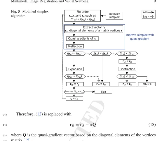
UNCORRECTED PROOF
Fig. 5 Modified simplex
algorithm
Therefore, (12) is replaced with
212
rR = rB− αQ (18)
213
where Q is the quasi-gradient vector based on the diagonal elements of the vertices
214
matrix [15].
215
5 Registration Versus Visual Servoing
216
5.1 Image Transformation
217
First, the considered registration is defined as a rigid transformation between two
218
images. Let us assume the transformation$r ∈ SE(3) = R(3) × SO(3) between the
219
white light image Ib1and the fluorescence image Ib2. Thereby, this transformation
220
can be estimated by minimizing the value of MI(Ib1,Ib2):
221
$r = arg min −MI[Ib1(r), Ib2] | r ∈ SE(3) (19)
222
where r is a possible rigid transformation.
223
The process allowing to carry out this registration is operating as follows:
acqui-224
sition of both white light image Ib1 and fluorescence image Ib2 then computing
225
MI(Ib1, Ib2). The obtained transformation$rfrom the first optimization is then applied
226
UNCORRECTED PROOF
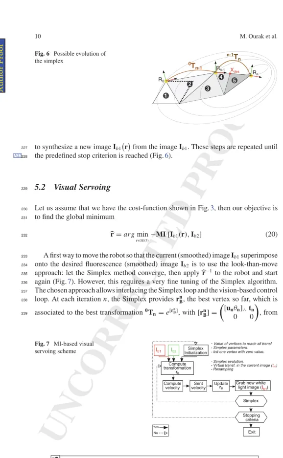
Fig. 6 Possible evolution of
the simplex 1 2 3 R0 Rn 0T n-1 n-1T n Xdes 4 Rn-1 5
to synthesize a new image Ib1"r#from the image Ib1. These steps are repeated until
227
the predefined stop criterion is reached (Fig.6).
AQ2228
5.2 Visual Servoing
229
Let us assume that we have the cost-function shown in Fig.3, then our objective is
230
to find the global minimum
231
$r = arg min
r∈SE(3)−MI [Ib1
(r), Ib2] (20)
232
A first way to move the robot so that the current (smoothed) image Ib1superimpose
233
onto the desired fluorescence (smoothed) image Ib2 is to use the look-than-move
234
approach: let the Simplex method converge, then apply $r−1 to the robot and start
235
again (Fig.7). However, this requires a very fine tuning of the Simplex algorithm.
236
The chosen approach allows interlacing the Simplex loop and the vision-based control
237
loop. At each iteration n, the Simplex provides rn
B, the best vertex so far, which is
238
associated to the best transformation0T
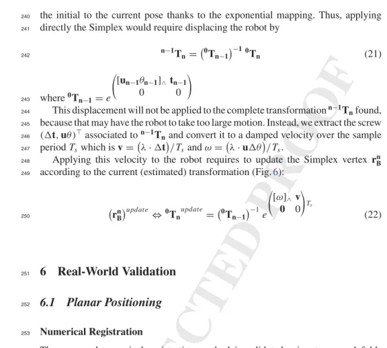
n= e[rnB], with[rn B] = % [unθn]∧tn 0 0 & , from 239
Fig. 7 MI-based visual
servoing scheme
UNCORRECTED PROOF
the initial to the current pose thanks to the exponential mapping. Thus, applying
240
directly the Simplex would require displacing the robot by
241 n−1T n="0Tn−1#−1 0Tn (21) 242 where0T n−1= e ⎛ ⎝[un−1θn−1]∧ tn−1 0 0 ⎞ ⎠ 243
This displacement will not be applied to the complete transformationn−1Tnfound,
244
because that may have the robot to take too large motion. Instead, we extract the screw
245
('t, uθ)⊤associated ton−1Tnand convert it to a damped velocity over the sample
246
period Tswhich is v="λ· 't#/Tsand ω="λ· u'θ#/Ts.
247
Applying this velocity to the robot requires to update the Simplex vertex rn B
248
according to the current (estimated) transformation (Fig.6):
249 " rn B #update ⇔0T nupdate="0Tn−1#−1e ⎛ ⎝[ω]∧v 0 0 ⎞ ⎠Ts (22) 250
6 Real-World Validation
2516.1 Planar Positioning
252 Numerical Registration 253The proposed numerical registration method is validated using two vocal folds
254
images: real fluorescence and white light. These images taken from [1] were acquired
255
in two different points of view with known pose as shown in Fig.8. It can be
256
(a) (b)
Fig. 8 a Fluorescence image Ib2and b white light image Ib1
UNCORRECTED PROOF
(a) (b)
Fig. 9 Numerical registration results: a shows Ib1integrated in Ib2, and b a zoom in the region of
interest
highlighted that $rbetween Ib1and Ib2includes four parameters (x, y, θ and zoom).
257
To be more realistic in our validation tests, we added a circular trajectory (i.e.,
vir-258
tual incision mark done by a surgeon), to be tracked by the surgical laser spot, in the
259
fluorescence image delimiting the tumor (Fig.8). Then by analyzing Fig.9a, can be
260
underlined the continuity of the combination (Ib1+ Ib2), which relates to the high
261
accuracy of the registration method. This accuracy is clearly visible on the zoom in
262
the incision mark (Fig.9b). For this example, the numerical values are summarized
263
in Table1.
264
Visual Servoing
265
For ethical reasons, we have not yet performed trials in a clinical set-up. Therefore,
266
we validated the method on two benchmarks. The first one is a 3 DOF (x, y, θ)
267
microrobotic cell (Fig.10).
268
Firstly, the MI-based visual servoing is validated on monomodal images in aim
269
to verify the validity of our controller. Figure11a represents an example of white
270
light images registration in visual servoing mode. More precisely, Fig. 11a(a, b)
271
represent the initial and desired images, respectively. In the same way, Fig.11a(c, d)
272
show the initial and final error Ib1− Ib2. It can be noticed that the final position of
273
the positioning platform matches perfectly with the desired position indicating good
274
accuracy of our method.
275
Table 1 Numerical values of
$r,$z (1pix = 0.088mm) DOFx(mm) Real pose Obtained pose Errors
−8.000 −7.767 0.233
y(mm) −12.000 −12.059 0.059
θ(deg) 12.000 12.500 0.500
z 1.09 1.089 0.010
UNCORRECTED PROOF
Camera Vocal folds photography stage x stage y stage P1 P2 R1 R: revolute P: prismaticFig. 10 Global view on the 3DOF experimental platform
(a) (a) (b) (c) (d) (a) (b) (c) (d) (b) (c) (d)
Fig. 11 Image snapshots acquired during the SE(2) positioning: a white light versus white light
images, b white light versus fluorescence images. Velocities vx, vyand ωz(in µm/s, mrad/s) versus
iterations in the case of: c white light versus white light image, d fluorescence versus white light image
UNCORRECTED PROOF
Figure11c shows the evolution of the velocities vx, vy and ωz in the different
276
DOF versus number of iterations. It can be underlined that the developed controller
277
converges with accuracy in fifty iterations (each iteration takes about 0.5 s). Also,
278
the speed varies in the iteration 40 because the Simplex after initialization found a
279
new best minimum.
280
Secondly, vocal folds multimodal images are also used to test the proposed
con-281
troller. In this scenario, the desired image is in fluorescence mode (prerecorded
282
image) and the current images are in white light mode as it would be in the surgical
283
context. Figure11b(a, b) show the initial image Ib1and the desired image Ib2,
respec-284
tively. Figure11b illustrate the error (Ib1− Ib2)during the visual servoing process.
285
As shown in this figure, the controller converges also to the desired position with a
286
good accuracy. Note that the image (Ib1− Ib2)is not completely gray (if two pixels
287
are exactly the same, it is assigned the gray value of 128 for a better visualization of
288
(Ib1− Ib2), this is due to the fact that both images are acquired from two different
289
modalities, then the difference will never be zero (respectively 128 in our case).
290
In the same manner, Fig.11d shows the evolution of the velocities vx, vyand ωz
291
with respect number of iterations. It can be also underlined that the controller
con-292
verges with the accuracy to the desired position despite the large difference between
293
Ib1and Ib2.
294
Additional validation tests were performed to assess the repeatability and behavior
295
(convergence and robustness) of the controller. Therefore, for each test, the
experi-296
mental conditions (lighting conditions, initial position and image quality) were
delib-297
erately altered. Table2gives the results of a sample of these experiments.
298
Table 2 Repeatability test
for visual servoing (x, y, errorin mm, θ in◦and t in
seconds)
No. DOF Des. pos. Ini. pos. Error t
1 x 5.37 2.47 −0.33 25.2 y 2.94 0.66 0.37 θ −2.61 −8.43 2.51 2 x 4.02 −0.66 0.37 36.5 y −5.57 −5.05 1.45 θ 2.47 −5.05 2.41 3 x 6.05 3.14 0.16 49.2 y 1.47 0.21 0.88 θ −14.59 −24.19 0.64 4 x 4.09 2.1 0.17 36.3 y 2.12 0.44 0.4 θ 14.56 6.63 1.15 5 x 3 0.31 0.55 57.3 y 2.5 0.19 0.53 θ −4.81 14.53 0.83 Author Proof
UNCORRECTED PROOF
6.2 3D Positioning
299
Numerical Registration
300
This numerical registration was tested in the same condition as in the planar numerical
301
registration experiment. However, in this case the transformation between Ib1and Ib2
302
is$r ∈ SE(3). As in the previous experiment, we use the fluorescence image (Fig.12a)
303
versus white light (Fig.12a) image, with circular trajectory of the laser spot draw
304
by the surgeon in both images. The initial Cartesian error between the desired image
305
Ib1and the current image Ib2, was r = (30, 30, 40 mm, 4◦, 10◦, 5◦).
306
Again in this experiment we can see overlapping between the reference and the
307
transformed image in the combined image Fig.13c. The resulting image is the sum
308
between a region of current image (Fig. 13a) and the transformed one with the
309
returned registration values (Fig.13b) to show the continuity of the vocal fold shape.
310
Besides, the real final error is δr = (0.22, 1.29, 9.5 mm, 0.29◦, 0.86◦, 1.02◦), with a
311
computation time of 6.564 s.
312
Visual Servoing
313
The previous experiment on the visual servoing was extended to the 6 DOF robot
314
platform with an eye-to-hand configuration as shown in the Fig.14(left). The test
315
Fig. 12 a Fluorescence image Ib2and b white light image Ib1
(a) (b) (c)
Fig. 13 Numerical registration results: a shows a sample region of Ib1, b shows a sample region of
Ib2after applying the numerical registration transformation, and c the combination of the images
(a) + (b)
UNCORRECTED PROOF
Fig. 14 Global view on the 6 DOF experimental platform
(a) (b)
(c) (d)
Fig. 15 Image sequence captured during the positioning task. a Desired image Ib1, b current image
Ib2, c initial difference Ib1− Ib2and d final difference Ib1− Ib2showing that the controller reaches the desired position
UNCORRECTED PROOF
consists in the validation of our controller without any information of the setup as
316
an interaction matrix or calibration parameters.
317
The approach consists of 3D positioning of the robot based on desired image,
318
Fig.15a (planer image (i.e., photography of vocal fold)) from current image Fig.15b
319
chosen arbitrary at the workspace of the robot. To do so, the robot is placed at an initial
320
position r = (−6, 6, 75mm, −1◦,−1◦,−1◦) and must reach the desired position r∗=
321
(6,−6, 74mm, −4◦, 2◦, 1◦). While, the Fig.15c presents the initial image difference
322
(Ib1− Ib2)and Fig.15d the final image difference when the controller reaches the
323
desired position. The positioning errors in each DOF are computed using the robot
324
encoders. The final error obtained is δr = (1.22, 0.352, 0.320 mm, 1.230◦, 1.123◦,
325
0.623◦). By analyzing this numerical value, it can be underlined the convergence of
326
the proposed method.
327
In Fig.16a, b illustrate the velocities v evolution sends to the robot during the
328
positioning task relative to the number of iterations (each iteration takes 0.5 s).
Fur-329
thermore, the mutual information values evolution decay is presented in Fig. 16c
330
with respect to the number of iterations.
331
(a) (b)
(c)
Fig. 16 a Translation velocities v (in mm/s), b rotation velocities ω (in rad/s), c mutual information
values evolution
UNCORRECTED PROOF
7 Conclusion
332
In this paper, a novel metric visual servoing-based on mutual information has been
333
presented. Unlike the traditional methods, the developed approach was based only
334
on the use of a modified Simplex optimization. It has been shown that the designed
335
controller works even in the presence of many local minima in the mutual
informa-336
tion cost-function. Beside this, the controller has shown good behavior in terms of
337
repeatability and convergence. Also, we have validated the controller in SE(3) using
338
a 6 DOF robot.
339
Future work will be devoted to optimize the computation time to reach the video
340
rate and improve the velocity control trajectories.
AQ3341
Acknowledgments This work was supported by µRALP, the EC FP7 ICT Collaborative Project
342
no. 288663 (http://www.microralp.eu), by French ANR NEMRO no ANR-14-CE17-0013-001, and
343
by LABEX ACTION, the French ANR Labex no. ANR-11-LABX-0001-01 (
http://www.labex-344
action.fr).
345
References
346
1. Arens, C., Dreyer, T., Glanz, H., Malzahn, K.: Indirect autofluorescence laryngoscopy in the
347
diagnosis of laryngeal cancer and its precursor lesions. Eur. Arch. Oto-Rhino-Laryngol. Head
348
Neck 261(2), 71–76 (2004)
349
2. Chaumette, F., Hutchinson, S.: Visual servo control, Part 1: basic approaches. IEEE Robot.
350
Autom. Mag. 13(1), 82–90 (2006)
351
3. Collewet, C., Marchand, E.: Photometric visual servoing. IEEE Trans. Robot. 27(4), 828–834
352
(2011)
353
4. Dame, A., Marchand, E.: Entropy-based visual servoing. In: IEEE International Conference
354
on Robotics and Automation, pp. 707–713 (2009)
355
5. Dame, A., Marchand, E.: Mutual information-based visual servoing. IEEE Trans. Robot. 27(5),
356
958–969 (2011)
357
6. Degani, A., Choset, H., Wolf, A., Zenati, M.A.: Highly articulated robotic probe for minimally
358
invasive surgery. In: IEEE International Conference on Robotics and Automation, pp. 4167–
359
4172 (2006)
360
7. Dowson, N., Bowden, R.: A unifying framework for mutual information methods for use in
361
non-linear optimisation. Lect. Notes Comput. Sci. 3951, 365–378 (2006)
362
8. Eckel, H., Berendes, S., Damm, M., Klusmann, J.: Suspension laryngoscopy for endotracheal
363
stenting. Laryngoscope 113, 11–15 (2003)
364
9. Jackel, M., Martin, A., Steine, W.: Twenty-five years experience with laser surgery for head
365
and neck tumors. Eur. Arch. Oto-Rhino-Laryngol. 264, 577–585 (2013)
366
10. Kelley, C.: Iterative Methods for Optimization. Frontiers in Applied Mathematics, vol. 18
367
(1999)
368
11. Marchand, E., Collewet, C.: Using image gradient as a visual feature for visual servoing. In:
369
IEEE/RSJ International Conference on Intelligent Robots and Systems, pp. 5687–5692 (2010)
370
12. Miura, K., Hashimoto, K., Gangloff, J., de Mathelin, M.: Visual servoing without Jacobian using
371
modified simplex optimization. In: IEEE International Conference on Robotics and
Automa-372
tion, pp. 3504–3509 (2005)
373
13. Nelder, A., Mead, R.: A simplex method for function minimization. Comput. J. 7, 308–313
374
(1965)
375
321066_1_En_9_Chapter!TYPESET DISK LE!CP Disp.:22/3/2016 Pages: 20 Layout: T1-Standard
![Fig. 2 Vocal folds endoscopic images: a white light endoscopic image, b fluorescence endoscopic image [18]](https://thumb-eu.123doks.com/thumbv2/123doknet/8096053.271588/5.892.202.690.737.933/vocal-folds-endoscopic-images-white-endoscopic-fluorescence-endoscopic.webp)