Titre: Title:
Development of a Model to Predict the Water Retention Curve Using Basic Geotechnical Properties
Auteurs:
Authors: Michel Aubertin, M. Mbonimpa, B. Buissière, R.P. Chapuis Date: 2003
Type: Rapport / Report Référence:
Citation:
Aubertin, Michel, Mbonimpa, M., Buissière, B. et Chapuis, R. P. (2003). Development of a Model to Predict the Water Retention Curve Using Basic Geotechnical Properties. Rapport technique. EPM-RT-2003-01.
Document en libre accès dans PolyPublie Open Access document in PolyPublie
URL de PolyPublie:
PolyPublie URL: http://publications.polymtl.ca/2604/
Version: Version officielle de l'éditeur / Published versionNon révisé par les pairs / Unrefereed Conditions d’utilisation:
Terms of Use: Autre / Other
Document publié chez l’éditeur officiel
Document issued by the official publisher
Maison d’édition:
Publisher: École Polytechnique de Montréal URL officiel:
Official URL: http://publications.polymtl.ca/2604/ Mention légale:
Legal notice: Tous droits réservés / All rights reserved
Ce fichier a été téléchargé à partir de PolyPublie, le dépôt institutionnel de Polytechnique Montréal
This file has been downloaded from PolyPublie, the institutional repository of Polytechnique Montréal
EPM–RT–2003-01
DEVELOPMENT OF A MODEL TO PREDICT THE WATER RETENTION CURVE USING BASIC
GEOTECHNICAL PROPERTIES
Michel Aubertin, M. Mbonimpa, B. Bussière, R.P. Chapuis Département des génies civil, géologique et des mines
École Polytechnique de Montréal
EPM-RT-2003-01
DEVELOPMENT OF A MODEL TO PREDICT
THE WATER RETENTION CURVE USING
BASIC GEOTECHNICAL PROPERTIES.
M. AUBERTINA,1*, M. MBONIMPAA,1, B. BUSSIÈREB,1, and R.P. CHAPUISA
A Department of Civil, Geological and Mining Engineering, École Polytechnique de Montréal, P.O. Box 6079, Stn. Centre-ville, Montreal, Québec, H3C 3A7, Canada.
B Department of Applied Sciences, Université du Québec en Abitibi-Témiscamingue (UQAT), 445 boul. de l’Université, Rouyn-Noranda, Québec, J9X 5E4 Canada.
1 Industrial NSERC Polytechnique-UQAT Chair on Environment and Mine Wastes Management
2003 Dépôt légal :
Michel Aubertin, Mamert Mbonimpa, Bibliothèque nationale du Québec, 2003 Bruno Bussière et R.P. Chapuis Bibliothèque nationale du Canada, 2003 Tous droits réservés
EPM-RT-2003-01
Oxygen diffusion and consumption in unsaturated cover materials
by: Michel AubertinA,1, Mamert MbonimpaA,1, Bruno BussièreB,1 et Robert P. ChapuisA.
A Department of Civil, Geological and Mining Engineering, École Polytechnique de Montréal B Department of Applied Sciences (UQAT), Rouyn-Noranda
1 Industrial NSERC Polytechnique-UQAT Chair on Environment and Mine Wastes Management
Toute reproduction de ce document à des fins d’étude personnelle ou de recherche est autorisée à la condition que la citation ci-dessus y soit mentionnée.
Tout autre usage doit faire l’objet d’une autorisation écrite des auteurs. Les demandes peuvent être adressées directement aux auteurs (consulter le bottin sur le site http://www.polymtl.ca) ou par l’entremise de la Bibliothèque :
École Polytechnique de Montréal
Bibliothèque – Service de fourniture de documents Case postale 6079, Succursale « Centre-Ville » Montréal (Québec)
Canada H3C 3A7
Téléphone : (514)340-4846
Télécopie : (514)340-4026
Courrier électronique : [email protected]
Pour se procurer une copie de ce rapport, s’adresser à la Bibliothèque de l’École Polytechnique de Montréal. Prix : 25.00$ (sujet à changement sans préavis)
Régler par chèque ou mandat-poste au nom de l’École Polytechnique de Montréal.
Toute commande doit être accompagnée d’un paiement sauf en cas d’entente préalable avec des établissements d’enseignement, des sociétés et des organismes canadiens.
ABSTRACT
The water retention curve (WRC) has become a key material function to define the unsaturated behavior of soils and of other particulate media. In many instances, it can be very useful to have an estimate of the WRC early in a project, when little or no test results are available. Predictive models, based on easy to obtain geotechnical properties, can also be employed to evaluate how changing parameters (e.g. porosity or grain size) affect the WRC. In this paper, the authors present a general set of equations developed for predicting the relationship between volumetric water content θ (and the corresponding degree of saturation Sr) and suction ψ. The proposed
WRC model is a modified version of the Kovács (1981) model, which makes a distinction between water retention due to capillary forces and retention by adhesion. The complete set of equations is given together with complementary relationships developed for specific applications on granular materials and on plastic/cohesive (clayey) soils. It is shown that the model provides a simple and practical means to estimate the water retention curve from basic properties. A discussion follows on the capabilities and limitations of the model.
RÉSUMÉ
La courbe de rétention d’eau (CRE) est devenue une fonction clé pour définir le comportement non saturé des sols et d'autres matériaux meubles. Dans beaucoup de cas, il peut être très utile d'avoir une évaluation de la CRE dans les premières phases d’un projet, lorsque peu ou pas de résultats d'essais sont disponibles. Des modèles prédictifs, basés sur les propriétés géotechniques de base, peuvent aussi être utilisés pour évaluer comment le changement des paramètres (en termes de porosité ou de granulométrie) affecte la CRE. Dans cet article, les auteurs présentent un ensemble d'équations développées pour prédire la relation entre la teneur en eau volumique θ (et le degré de saturation Sr correspondant) et la succion ψ. Le modèle proposé pour la prédiction
de la CRE est une version modifiée du modèle de Kovács (1981), qui fait une distinction entre la rétention d’eau due aux forces capillaires et celle par adhésion. Ce jeu d'équations est donné avec des relations complémentaires développées pour des applications spécifiques sur des matériaux granulaires et sur des sols (argileux) plastiques/cohérents. Il est montré que le modèle constitue un moyen simple et pratique pour estimer la courbe de rétention d’eau à partir des propriétés géotechniques de base. Une discussion suit sur les capacités et les limitations du modèle.
Mots clés: courbe de rétention d’eau, sols non saturés, prédiction, porosité, granulométrie, limite de liquidité.
ACKNOWLEDGEMENTS
The post-doctoral grant provided to the first author (Mamert Mbonimpa) by the Institut de Recherche en Santé et Sécurité du Travail du Québec (IRSST) is thankfully acknowledged. Special thanks also go to Antonio Gatien and to the graduate students who performed the diffusion tests over the years. The authors also received financial support from NSERC and from a number of industrial participants to the industrial NSERC Polytechnique-UQAT Chair on Environment and Mine Wastes Management.
TABLE OF CONTENTS
1. INTRODUCTION...1
2. BASIC CONCEPTS...4
3. THE MK MODEL ...6
3.1 The equivalent capillary rise ...7
3.2 The WRC equations ...11
4. APPLICATIONS...17
4.1 Residual suction ...17
4.2 Parameter ac and m...22
5. DISCUSSION ...28
5.1 Prediction of the residual suction and air entry value ...29
5.2 The equivalent capillary rise hco...34
5.3 Parameters with preset values ...36
5.4 Final remarks...38
6. CONCLUSION...39
7. REFERENCES ...41
LIST OF NOTATIONS
ac adhesion coefficient (-) Av surface of voids (cm2)
b coarse grained material parameter to calculate hco,G (cm2) b1 coarse grained material parameter to estimate ψa (cmx1+1) b2 coarse grained material parameter to correlate hco,G and ψa (-) Cψ corrector factor (-)
CU uniformity coefficient (-) (CU=D60/D10) d diameter of a tube (cm)
D10 diameter corresponding to 10% passing on the cumulative grain-size
distribution curve (cm)
D60 diameter corresponding to 60% passing on the cumulative grain-size
distribution curve (cm)
deq equivalent pore size diameter (cm) DH equivalent grain size diameter (cm)
e void ratio (-)
Dr specific gravity of the solid particles (-) hc capillary rise in a tube (cm)
hcmax maximum capillary rise [L] hcmin minimum capillary rise [L]
hco equivalent capillary rise in a porous material (cm)
hco,G equivalent capillary rise in a coarse grained material (cm) hco,P equivalent capillary rise in a plastic/cohesive material (cm) m pore size distribution parameter in the MK model (-)
n porosity (-)
Sr degree of saturation (-)
σw surface tension of water (N/m) ua air pressure (cm)
uw water pressure (cm) Vv volume of the voids (cm3) w gravimetric water content (-) wL liquid limit (%)
wP plastic limit (%)
x1 coarse grained material parameter to estimate ψa (-)
x2 coarse grained material parameter to correlate hco,G and ψa (-)
ψ suction (cm)
ξ plastic/cohesive material parameter required to calculate hco,P (cm)
ρs solid grain density (kg/m3)
α shape factor (-)
χ material parameter used to estimate Sm (-)
λ material parameter used to estimate Sm (m2/g)
θ volumetric water content (-)
ψ0 suction at complete dryness (Sr = 0) (cm)
ψ90 suction corresponding to a degree of saturation of 90% (cm)
ψ95 suction corresponding to a degree of saturation of 95% (cm)
ψa air entry value or AEV (cm)
ψa,exp air entry value determined from the experimental data (cm)
ψa,MK air entry value determined from the WRC predicted with the MK model (cm)
ψr residual suction (corresponding to the residual water content) (cm)
ψr,exp residual suction determined from the experimental data (cm)
βw contact angle (-)
LIST OF FIGURES
Figure 1. Illustration of the capillary and adhesion saturation contributions to the total degree of saturation for a non cohesive (low plasticity) soil in the MK model (for D10 = 0.006 cm, CU = 10, e=0.6; ψr =190 cm, m=0.1 and ac=0.01); ψa is the
pressure (suction) corresponding to the air entry value (AEV), ψr is the pressure
corresponding to the residual water content (also called water entry value-WEV), and ψ90 and ψ95 are suctions corresponding to a degree of saturation Sr of 0.90 and
0.95 respectively.---13 Figure 2. Illustration of the capillary and adhesion saturation contributions to the total
degree of saturation for a cohesive (plastic) soil (for wL=30%, e=0.6, ρs =2700
kg/m3, ψr =9.7x105 cm, m=3x10⁻⁵, and ac=7x10⁻⁴); ψa is the pressure (suction)
corresponding to the air entry value (AEV), ψ90 and ψ95 are suctions corresponding
to a degree of saturation Sr of 0.90 and 0.95 respectively. ---14
Figure 3. Effect of the pore size distribution parameter m on the position and shape of
the WRC according to the MK model. ---15 Figure 4. . Effect of the residual suction ψr on the WRC according to the MK model. ---16
Figure 5. Effect of the adhesion coefficient ac on the WRC according to the MK model. ---16
Figure 6. Relationship between the residual suction ψr,,exp determined from the
experimental data (with best fit WRC), the void ratio e, and the equivalent grain size diameter DH for granular materials identified in Table 1 (DH is defined by
equations 5 and 6). ---20 Figure 7. Relationship between the residual suction ψr,,exp determined from the
measured data (and best fit WRC), and the equivalent capillary rise hco,G (eq. 7) for
granular materials. ---21 Figure 8. Comparison of the ψr values obtained from equations 19 (see Figure 6) and 20
Figure 10. Application of the MK model to a fine, uniform, and dense sand (data
from Bruch 1993). ---25 Figure 11. Application of the MK model to tailings Sigma (silty material, well-graded,
and loose) (data from authors).---25 Figure 12. Application of the MK model to tailings Sigma mixed with 10 % bentonite
(data from authors). ---26 Figure 13. Application of the MK model to Guadalix red silty clay (data from Vanapalli
et al. 1998) ---26 Figure 14. Application of the MK model to a till (data from O’Kane et al. 1998) ---27 Figure 15. Application of the MK model to Indian Head Till (data from Fredlund 1999) ---27 Figure 16. Comparison between the air entry values obtained from the experimental
data ψa,exp (with best fit WRC) and obtained on the WRC predicted by the MK
model (ψa,MK) for granular materials.---31
Figure 17. Proposed relationships for estimating the air entry value ψa,exp obtained on
the experimental data for granular materials.---32 Figure 18. Proposed relationship for estimating the air entry value ψa,MK obtained on the
WRC predicted by the MK model for granular materials.---33 Figure 19. Relationships between the predicted air entry value ψa,MK and suctions ψ90,MK
and ψ95,MK corresponding respectively to degrees of saturation of 90% and 95%,
(obtained on the WRC predicted by the MK model) for granular materials. ---34 Figure 20. Relationships between the equivalent capillary rise hco,G and the air entry
value for granular materials; ψa,exp and ψa,MK are obtained on the experimental and
LIST OF TABLES
Table 1. Nature, origin, and basic geotechnical properties of the granular materials.---18 Table 2. Nature, origin, and basic geotechnical properties of the plastic/cohesive
materials. ---19 Table 3. Parameters m and ac leading to the best fit WRC shown in Figures 9 to 15, and
the empirically determined values. ---28 Table A-1. Typical calculation results to predict the WRC of granular materials: Case of
Sigma tailings (see Figure 11- data from Authors). ---50 Table A-2. Typical calculation results to predict the WRC of plastic/cohesive soils: Case
1.
INTRODUCTIONIn geotechnical engineering, subsurface water is often divided into free water in the saturated zone and moisture retained in the unsaturated (vadose) zone (e.g. Bowles 1984; Smith 1990; McCarthy 1998). Even if the behavior of water and soils under saturated condition can be treated as a special case of the more general partially saturated situation (e.g. Fredlund and Rahardjo 1993), such distinction is justified by the physical differences that characterize the two zones. Owing to the particularities that exist in unsaturated soils, special attention should be paid to adequately define the response of water above the phreatic surface.
Geotechnique for unsaturated media is a rapidly expanding field, which is related to a wide variety of applications in soil mechanics and soil physics including: estimation of field capacity (Meyer and Gee 1999); efficiency analysis of covers with capillary barrier effects (Nicholson et al. 1989; Aubertin et al. 1993, 1995a, 1996, 1997; Khire et al. 1995; O’Kane et al. 1998; Morris and Stormont 1999; Bussière 1999); bearing capacity of unsaturated foundation materials (Rassam and Williams 1999); seepage through dams (Chapuis et al. 1996, 2001; Fredlund 2000a); compressibility and swelling soil response (Fredlund, 1987; Rampino et al. 2000; Hung and Fredlund 2000); shear strength and constitutive behavior (e.g. Alonso et al. 1990; Fredlund et al. 1996, Vanapalli et al. 1996; Cui and Delage 1996); contaminant transport (Badv and Rowe 1996; Lim et al. 1998; Barbour 1998, Esposito et al. 1999); land subsidence (Thu and Fredlund 2000); freeze-thaw response of road structures (Konrad and Roy 2000). Fredlund (2000a) presents an interesting overview of various applications of unsaturated soil mechanics.
The distribution and motion of water in the unsaturated zone are closely related to forces caused by molecular attraction responsible for water adhering to solid surfaces (i.e. hygroscopic or adsorbed water on soil particles) and for surface tension causing capillary retention due to cohesion between water molecules at the interface with air (e.g. Bear 1972; Marshall et al. 1996). In saturated media, the adsorption forces tend to reduce the space available for water flow, hence reducing the effective porosity and hydraulic conductivity, while capillary forces disappear in the
absence of a water-air interface. In partly saturated conditions, these two distinct but complementary types of force affect the hydrogeological and mechanical behavior of soils. The corresponding properties, including hydraulic conductivity and shear strength parameters, are no longer material constants but rather depend on the relative amount of water and gas in the pore space.
The quantity of water retained in a soil by capillary and adhesion forces depends on many factors, namely: shape, size and distribution of pore space; mineralogy and surface activity of solid grain particles; chemical composition of interstitial water. Richards (1931) equation, which is a combination of Darcy’s law and conservation equation, is commonly used to solve groundwater flow problems for variably saturated conditions. In this equation, the hydraulic conductivity is a function of the state variables, which are typically expressed in terms of volumetric water content θ or of suction ψ (e.g. Leong and Rahardjo 1997a; Leij et al. 1997). For a given porous media, these two parameters, θ and ψ, are related to each other and form what is being considered as a fundamental material characteristic identified here as the water retention curve WRC. Many other names are used for the θ-ψ relationship, including the soil-water characteristic curve (SWCC) which however becomes less appropriate when dealing with other types of porous material (such as ceramic plates or geotextiles) and with man made particulate media (such as mined rock wastes and tailings).
In a porous system, increasing the value of suction ψ (defined by ua-uw, where ua is the air (gas)
pressure and uw is the water pressure) tends to reduce θ. The desaturation is typically more
pronounced in coarse grained materials (such as sand and gravel) than in fine grained materials (such as silt and clay). The value of θ at a given ψ also depends on the path, whether it occurs during a wetting or drying phase. Different paths induce somewhat different curves (e.g. Parlange 1976; Mualem 1984), but such hysteresis phenomena will not be addressed directly here, as only the drainage path is considered (to simplify the presentation).
When θ is diminished, the flow of water is more difficult because of the reduced area available in the water phase. The unsaturated hydraulic conductivity ku thus depends on θ (or ψ). At a
sufficiently low water content, the water phase becomes discontinuous and ku is reduced to a very
small (near zero) value.
To perform groundwater flow analyses as required in a number of applications in geotechnique and soil physics, engineers and scientists must be able to quantify the ku function. Because direct
measurement of ku can be difficult, time consuming and costly, it is customary to use, as a
starting point, some relationship between θ and ψ (e.g. Mualem 1976, 1986; Fredlund et al. 1994) because the WRC can be evaluated more easily than ku in the laboratory or in the field. The
resulting θ-ψ data, obtained from test measurements, are plotted and used to derive specific mathematical functions with curves that run through the data points. Such fitting equations have been proposed by Gardner (1956), Brooks and Corey (1964), Brutsaert (1966), Haverkamp et al. (1977), Vauclin et al. (1979), van Genuchten (1980), Bumb et al. (1992), Fredlund and Xing (1994), and Kosugi (1994), to name a few. These mathematical expressions with the corresponding parameter values deduced experimentally or otherwise, can be very useful for particular applications when the necessary data is available. Many of these equations have been compared to each other over the years (e.g. Khire et al. 1995; Leij et al. 1997; Leong and Rahardjo 1997b; Burger and Shackelford, 2001), showing that they each have some advantages and limitations, depending on the technique and data bank used for comparison.
In some cases, it can be very useful to obtain a priori an estimate of the WRC from easily and rapidly obtained properties. Unfortunately, most predictive models, sometimes referred to as pedotransfer functions (e.g. Verecken et al. 1992; Schaap and Leij 1998; Elsenbeer 2001), are based on empirically derived expressions that bear little physical meanings, and this limits their significance when trying to extend their use outside the range of properties considered for their development and calibration.
In the following, the authors propose a set of equations ensuing from the physical model originally developed by Kovács (1981). This model, which includes a capillary and an adhesion component, was previously used to predict the WRC of tailings from hard-rock mines (Aubertin
et al. 1998). In this paper, the model is generalized and all its components are explicitly defined so that it can be applied to a variety of homogeneous media, including coarse and fine grained soils, tailings, and bentonite mixtures.
2. BASIC CONCEPTS
The water retention curve (WRC) represents the relationship between the volumetric water content θ and suction ψ. The former parameter is related to porosity n and degree of saturation Sr
(θ=nSr). It can also be expressed as a function of the more common massic (gravimetric) water
content w (i.e. θ=w(1-n)Dr, where Dr is the relative density of the solid particles). The suction
value ψ, on the other hand, is typically expressed as a potential using either pressure units (ex. kPa), pressure head (ex. m of water), or centimetric logarithmic head (known as pF); at 20°C, 9.81kPa ≡ 100cm of water ≡ pF of 2. The total suction ψ is the sum of the matric potential ψm
and of the osmotic potential π, but the latter is often neglect in geotechnical applications (ψ = ψm
is assumed here). For convenience, ψ takes a positive value under negative water pressure uw
above the phreatic water surface (where uw=ua or ψ=ua-uw=0, with ua taken as the reference air
pressure).
A large number of experimental investigations have been devoted to developing and applying techniques to obtain the θ-ψ relationship of soils. Accordingly, various direct and indirect measurement methods have been proposed for the WRC, and many of these have been reviewed in recent textbooks and monographs (e.g. Klute 1986; Carter, 1993; Fredlund and Rahardjo 1993; Marshall et al. 1996). The evolution and understanding of the WRC and of the corresponding measurement techniques have been recently presented by Barbour (1998), who provides an interesting historical perspective.
Measurement of the WRC in the laboratory and in the field, although less demanding than that of ku, can be relatively time consuming and expensive. In some situations, it may be very useful to
have estimates of the WRC, especially during the preliminary stages of a project when the available information is limited. Predictive models for the WRC, which are usually based on simple geotechnical (pedologic) properties, such as grain size and porosity, can also be of help when analyzing and validating test results, and also for evaluating the variations that can be expected in the field within a non homogenous deposit.
Over the last two decades or so, quite a few predictive models have been proposed (see Elsenbeer 2001, and the corresponding Monograph Issue on the topic). These include a number of functional regression methods using some of the above mentioned empirical WRC equations. The fitting parameters are then related to particular textural parameters (e.g. Cosby et al. 1984; Schaap et al. 1998; Fredlund 2000b). Other discrete regression methods make no a priori assumption regarding the shape of the WRC, and construct empirical models from the regression equations linking the θ-ψ values and basic properties (e.g. Gupta and Larson 1979; Rawls and Brackensiek 1982; Rawls et al. 1991; Vereecken et al. 1992; Tietje and Tapkenhinrichs 1993). It appears preferable however to use predictive models for which the WRC equation is based on physical characteristics of the media. This latter type of model includes those of Arya and Paris (1981), Haverkamp and Parlange (1986), Tyler and Wheatcraft (1989, 1990), Haverkamp et al. (1999), and Arya et al. (1999).
Such a physically-based model was also proposed by Kovács (1981). Still relatively unknown and seldom used in the geotechnical field, the Kovács (1981) model recognizes the need to distinguish between capillary and adhesive forces. This approach potentially provides a more realistic view, as it can be related to the actual processes involved (e.g. Celia et al. 1995; Nitao and Bear 1996). However, the Kovács (1981) model, in its original version, did not easily lend itself to practical engineering applications because of the relatively poor definition of key parameters needed for its use. The authors have nevertheless been able to apply it, after some modifications (hence the name Modified Kovács or MK model) to the WRC of artificial silts or tailings (Aubertin et al. 1998). In the following, the MK model is extended for general applications to various types of soils, from coarse sand to clayey materials. The basic
assumptions and theoretical considerations behind these extensions are briefly presented. The descriptive and predictive capabilities of the MK model are shown using tests results taken from the literature and obtained in the author’s own facilities.
3. THE MK MODEL
The Kovács (1981) model is used here as the basis to develop a practical set of equations for predicting the WRC of various types of soils from commonly used geotechnical properties. The original model has been described in details in Kovács’ (1981) textbook, and was also reviewed by the authors in a paper where the model has been adapted for tailings from hard rock mines (Aubertin et al., 1998). Hence, only its basic components will be recalled.
The proposed MK model presented in the following retains the sound physical concepts from which the original model was constructed. The non-trivial modifications introduced serve to generalize the statistical function used to describe the pore-size distribution of the media appearing in the capillary component. Some parameters, ill defined originally, are expressed more specifically as a function of basic soil properties. The ensuing set of equations allows the user to obtain an evaluation of the WRC, which can be employed for practical calculations involving problems with unsaturated conditions. As will be shown in the next sections, the MK model is easy to use and generally provides a good estimate of the WRC for various types of granular as well as plastic/cohesive materials. The MK model can also be used in a more classical (descriptive) manner to draw the WRC from a few relevant testing results. Because of their close relationship with material response, the model equations can be employed to evaluate the expected influence of changing properties on the WRC, such as varying grain size, porosity, or liquid limit.
3.1 The equivalent capillary rise
The MK model makes use of a parameter defined as the equivalent capillary rise hco [L] in the
porous medium. The role of this parameter is the same as the so-called average capillary rise in the original Kovács (1981) model. The adopted denomination is justified below. This parameter can be derived from the well-known expression used for the capillary rise hc [L] of water in a
tube having a diameter d. The value of hc is given by (Smith 1990; Chin 2000):
[1] d cos 4 h w w w c= σ γ β
where σw [MT-2] is the surface tension of water (σw =0.073 N/m at 20°C), βw [-] is the contact
angle between water and the tube surface (βw = 0° for quartz and glass), γw [ML-2T-2] is the unit
weight of water (γw=9.8 kN/m3 at 20°C). This well-known equation indicates that capillary rise is
inversely proportional to the diameter of the tube. When applied to pore space in soils above the phreatic surface, this equation helps to understand why there can be a much larger capillary rise in fine grained soils, where the voids (somewhat similar to capillary tubes) are small, than in coarse grained soils where the voids are typically larger.
In soils however, the pore size is not uniform so hc is not easily defined. This pore system can be
substituted by a system of regular channels with a diameter expressed as the equivalent hydraulic pore diameter deq [L] defined as (e.g. Bear 1972; Kovács 1981):
[2]
v v eq 4VA
d =
where Vv [L3] and Av [L2] are respectively the volume and surface of the voids. In practice, Av
approximately corresponds to the surface area AG [L2] of the solid grains. By relating AG to the
[3] m s eq 4 eS d ρ =
In this equation, e [-] is the void ratio (Vv/Vs, where Vs is the volume of the solid grains) and ρs
[ML-3] is the solid grain density.
The capillary rise hco of a soil above the water table, obtained by replacing diameter d (in
equation 1) by the equivalent hydraulic pore diameter deq, can therefore be expressed as:
[4] e S cos h s m w w w co=σ γ β ρ
Parameter hco defined by equation 4 is the equivalent capillary rise of the soil.
Although Sm can be directly measured by various techniques (e.g. Lowell and Shields 1984; Igwe
1991), in most practical cases, the value of Sm is not readily available. For coarse grained soils,
the specific surface area can nevertheless be estimated from the grain size distribution using the following expression (Kovács 1981):
[5] D S H s m= ρ α
where α [-] is a shape factor (6 ≤ α ≤ 18; α = 10 is used here - see discussion below), and DH [L]
is an equivalent particle diameter for a heterogeneous mixture. The equivalent diameter DH for a
heterogeneous mix of particles theoretically represents the diameter of a homogeneous mix (with a single size) that has the same specific surface area as the heterogeneous one.
[6] H w w w G , co cos eD h =σ γ β α
where subscript G stands for granular (low plasticity, low cohesion) materials, as opposed to clayey (plastic/cohesive) materials (which will be discussed below). In this equation, the contact angle βw will be taken as zero (e.g. Marshall et al. 1996).
In granular soils, DH can be evaluated by subdividing the grain size curve (e.g. Chapuis and
Légaré 1992). For practical geotechnical applications, the value of DH can also be approximated
using a function of a representative size, like the effective diameter D10 [L] (diameter
corresponding to 10 % passing on the cumulative grain-size distribution curve), and of the uniformity coefficient CU (i.e. DH=[1+1.17log(CU)]D10; Aubertin et al. 1998; Mbonimpa et al.
2000, 2002). For the capillary rise of water in granular soils, equation (6) is expressed as follow:
[7] 10 G , co eD b h = with [8] w U w ] 1 ) C log( 17 . 1 [ 10 b γ σ + =
Parameter b [L2] is expressed in cm2, while hco and D10 are expressed in cm. For the values of σw
and γw given above, equation 8 becomes:
[9] 1 17 1 75 0 + = ) C log( . . b U
These equations mean that, for a uniform sand with D10 = 0.01cm, CU = 5 and e = 0.6, b = 0.412
cm2, the equivalent capillary rise hco,G is about 69 cm, while for a silt with D10 = 0.0005 cm, CU=20 and e = 0.6, b = 0.297 cm2, and hco,G would be 990 cm approximately. These values of
hco,G are much larger than the height of the capillary fringe (as defined in most textbooks) which
rather represents more or less the air entry value (AEV) of the material. The physical meaning of these parameters will be further discussed below.
For clayey (plastic/cohesive) soils, the above equations can provide inadequate estimates of Sm
and hco, particularly when the liquid limit wL (%) is above about 30 to 40%. For such fine
grained soils, other factors influence their water retention capacity. In this case, Sm (in equation
4) is better estimated using the relationship that exists between the specific surface area and the liquid limit wL (%). The following expression, recently proposed by Mbonimpa et al. (2002), is
used here:
[10] S =m λ wLχ
where λ [L2M-1] and χ (unitless) are material parameters. Using a fairly large number of tests
results from various sources, it has been established that λ ≈ 0.2 m2/g and χ = 1.45 for materials
with 22 m2/g ≤ Sm ≤ 433 m2/g and 18 % ≤ wL ≤ 127 %.
Combining equations 4 and 10 gives:
[11] co,P w1L.45 e
h =ξ
where subscript P stands for plastic/cohesive materials. From the previous developments, parameter ξ [L] can be expressed as:
[12] s w w wcos λρ γ β σ ξ =
The units for ξ and hco,P are cm. For the above values of σw and γw, βw =0°, λ ≈ 0.2 m2/g, and ρs
in kg/m3, ξ becomes:
[13] ξ ≈0.15ρs
From equation 11 and 13, one can calculate that for a clayey soil with wL = 40%, ρs = 2700 kg/m3
and e= 0.8, ξ = 405 cm2, and h
co,P is equal to 106500 cm; for wL = 80%, ρs = 2700 kg/m3 and e =
0.8, one obtains ξ = 405 cm2 and h
co,P = 290968 cm. Again, these values are much larger than the
water rise corresponding to the capillary fringe. It will be seen below that hco should rather be
compared to the potential elevation (or suction ψr) for the residual water content.
3.2 The WRC equations
The MK model uses hco as a reference parameter to define the relationship between volumetric
water content θ and matric suction ψ. As mentioned above, both the original Kovács (1981) model and the MK model consider that water is held by two types of forces, i.e. capillary forces responsible for capillary saturation Sc and adhesive forces causing saturation by adhesion Sa. The Sc component equation is obtained from a cumulative pore size distribution function, while the
equation of Sa is given by an interaction law with van der Waals type attraction between grain
surface and water dipoles. The Sc component is more important at relatively low suction values,
while the Sa component becomes dominant at higher suction when capillary water has been
withdrawn.
The proposed set of equations for the MK model is written as follows for the degree of saturation
Sr:
[14] S S (1 S )
n
[15]
(
)
(
)
− + − = h ψ exp m h ψ S co m co c 2 2 1 1 [16] Sa* =1− 1−Sa [17](
)
( )
ψ ψ ψ ψ n / / n co / c a e h C a S 1 6 3 1 3 2 = with [18] ) 1 ln( ) 1 ln( 1 C r o r ψ ψ ψ ψ ψ + + − =Equation 14 expresses the total degree of saturation by combining the capillary and adhesion components with contributions of Sc and Sa* given by equations 15 to 18. In these equations m
and ac are material parameters, and ψr is the pressure (suction) corresponding to the residual
water content (ψr is also equal to the water entry value - WEV - when no distinction is made
between drainage and wetting path). Figures 1 and 2 show typical curves drawn from the MK model in a semi-log Sr-ψ plane, illustrating the contributions of Sc and Sa* for granular (Fig. 1a)
and plastic/cohesive (Fig 1b) materials. Hypothetical (but representative) values for D10, CU, e, wL, Gs, hco, m, ac, and ψr have been used for these plots. The value ψr and the pressure (suction)
corresponding to the air entry value ψa are also shown on these Figures together with two other
parameters ψ90 and ψ95 defining suctions for preset degrees of saturation (of 90% and 95%
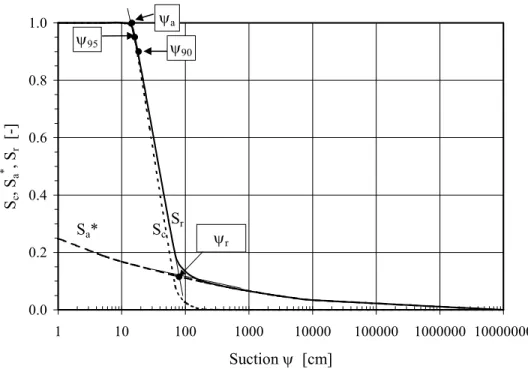
0.0 0.2 0.4 0.6 0.8 1.0 1 10 100 1000 10000 100000 1000000 10000000 Suction ψ [cm] Sc , Sa * , S r [-] ψr ψa Sc Sa* Sr ψ95 ψ 90
Figure 1. Illustration of the capillary and adhesion saturation contributions to the total degree of saturation for a non cohesive (low plasticity) soil in the MK model (for D10 = 0.006 cm, CU = 10,
e=0.6; ψr =190 cm, m=0.1 and ac=0.01); ψa is the pressure (suction) corresponding to the air
entry value (AEV), ψr is the pressure corresponding to the residual water content (also called
water entry value-WEV), and ψ90 and ψ95 are suctions corresponding to a degree of saturation Sr
of 0.90 and 0.95 respectively.
Equation 15 provides the expression to evaluate Sc (0 ≤ Sc ≤1) as a function of the equivalent
capillary rise hco (given by the expressions proposed above) and suction ψ. This equation is a
generalization of the one developed by Kovács (1981), in which the statistical exponential function has been expanded to better reflect the influence of pore-size distribution through the distribution parameter m. The statistical distribution expression used for Sc is one that can also be
applied for grain size curves, as there is a well-known similarity between the latter and the WRC (e.g. Aubertin et al. 1998; Fredlund et al. 2000).
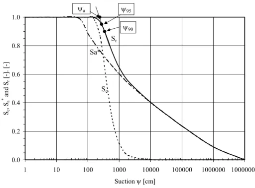
0.0 0.2 0.4 0.6 0.8 1.0 1 10 100 1000 10000 100000 1000000 10000000 Suction ψ [cm] Sc , Sa * and S r [-]. [-] ψ95 Sc Sr Sa* ψa ψ90
Figure 2. Illustration of the capillary and adhesion saturation contributions to the total degree of saturation for a cohesive (plastic) soil (for wL=30%, e=0.6, ρs =2700 kg/m3, ψr =9.7x105 cm,
m=3x10⁻⁵, and ac=7x10⁻⁴); ψa is the pressure (suction) corresponding to the air entry value
(AEV), ψ90 and ψ95 are suctions corresponding to a degree of saturation Sr of 0.90 and 0.95
respectively.
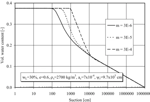
Figure 3 illustrates how the θ-ψ relationship is affected by the value of parameter m. As can be seen in this figure, both the position and the slope of the curve are related to m. On the WRC, parameter m influences the air entry value ψa (or AEV), which theoretically correspond to the
suction when the largest pores start to drain, and also to the rate of decline beyond ψa in the
capillary range. For practical applications, the value of m will be expressed as a function of some very basic geotechnical properties.
wL=30%, e=0.6, ρs=2700 kg/m3, ac=7x10⁻⁴, ψr=9.7x105 cm 0.0 0.1 0.2 0.3 0.4 1 10 100 1000 10000 100000 1000000 10000000 Suction [cm]
Vol. water content [-]
m = 3E-6
m = 3E-5
m = 3E-4
Figure 3. Effect of the pore size distribution parameter m on the position and shape of the WRC according to the MK model.
Equations 16 and 17 define the adhesion component, again as a function of hco and ψ. A
truncated value of Sa (i.e. Sa*) is used to make sure that the adhesion component does not exceed
unity at low suction (0 ≤ Sa* ≤1). In equation 16, 〈 〉 represents the Macauley brackets
(〈y〉=0.5(y+y)); for Sa ≥ 1, Sa* = 1, and for Sa < 1, Sa* = Sa. Equation 17 is based on Kovács
(1981) expression in which a sixth order hyperbola is used to relate the adhesion saturation (due to the film of water adsorbed on grain surface) to suction. In this equation, ac is the adhesion
coefficient (dimensionless) and ψn is a normalization parameter introduced for unit consistencies (ψn =1 cm when ψ is given in cm, corresponding to ψn =10-3 atmosphere). Parameter Cψ
(equation 18), taken from Fredlund and Xing (1994), forces the water content to zero when ψ reaches a limit imposed by thermodynamic equilibrium (θ = 0 at ψ = ψ0 = 107 cm of water,
corresponding approximately to complete dryness). In equation 18, ψr represents the suction at
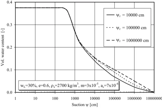
residual water content, which will be shown below to depend on basic soil properties (as is the case with ψa and hco). The effect of varying the value ψr in the MK model can be seen on Figure
4. Figure 5 shows the influence of the adhesion coefficient ac on the WRC (for typical clayey
wL=30%, e=0.6, ρs=2700 kg/m3, m=3x10⁻⁵, ac=7x10⁻⁴ 0.0 0.1 0.2 0.3 0.4 1 10 100 1000 10000 100000 1000000 10000000 Suction ψ [cm]
Vol. water content [-]
= 10000 cm = 100000 cm = 1000000 cm ψr ψr ψr
Figure 4.. Effect of the residual suction ψr on the WRC according to the MK model.
wL=30, e=0.6, ρs=2700kg/m3, ψr=9.7x105cm, m=3x10⁻⁵ 0.0 0.1 0.2 0.3 0.4 1 10 100 1000 10000 100000 1000000 10000000 Suction [cm]
Vol. water content [-]
= 0.0006
= 0.0007
= 0.0008ac
ac ac
4. APPLICATIONS
The MK model presented above includes a set of equations that provides an estimate of the WRC from full saturation (Sr = 1, θ = n) to complete dryness (Sr = 0 = θ). To apply the model however,
three open parameters in the constitutive equations have to be defined explicitly. These are parameter m in equation 15, ac in equation 17, and ψr in equation 18. Based on investigations
carried by the authors on a diversity of soils and particulate media, it has been found that the values of m, ac and ψr can be related to some very basic properties.
The experimental data used here for granular materials have been taken from various investigations performed on the properties of sands and low plasticity silts and tailings. The authors results have been obtained with either plate extractor or Tempe cell according to procedure described in Aubertin et al. (1995b, 1998), while some others have been taken from the literature (see Table 1). All the experimental results on plastic/cohesive materials have been taken from the literature (see Table 2). However, to limit the possibility of excessive shrinkage during testing (see Discussion), the clayey soils retained cover a relatively small range of liquid limit and porosity values.
4.1 Residual suction
To apply the model, the residual suction ψr introduced in the expression of factor Cψ was
evaluated first. For granular materials, values of ψr were determined using the tangent method
described by Fredlund and Xing (1994) (see Figure 1). The curves used to this end were obtained by fitting the experimental data with a descriptive equation (i.e. the van Genuchten (1980) model implemented in the code RETC; van Genuchten et al. 1991); the tangent method was then applied on the corresponding WRC best fit (N.B. the best fit curve could also have been obtained with the MK model).
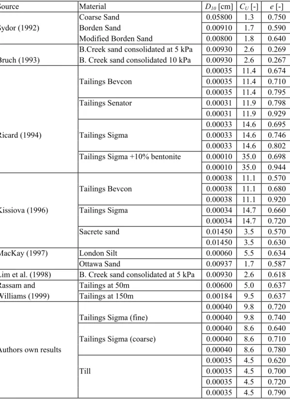
Table 1. Nature, origin, and basic geotechnical properties of the granular materials.
Source Material D10 [cm] CU [-] e [-]
Coarse Sand 0.05800 1.3 0.750 Sydor (1992) Borden Sand 0.00910 1.7 0.590 Modified Borden Sand 0.00800 1.8 0.640 B.Creek sand consolidated at 5 kPa 0.00930 2.6 0.269 Bruch (1993) B. Creek sand consolidated 10 kPa 0.00930 2.6 0.267 0.00035 11.4 0.674 Tailings Bevcon 0.00035 11.4 0.710 0.00035 11.4 0.795 Tailings Senator 0.00031 11.9 0.798 0.00031 11.9 0.929 0.00033 14.6 0.695 Ricard (1994) Tailings Sigma 0.00033 14.6 0.746 0.00033 14.6 0.802 Tailings Sigma +10% bentonite 0.00010 35.0 0.698 0.00010 35.0 0.944 0.00038 11.1 0.570 Tailings Bevcon 0.00038 11.1 0.680 0.00038 11.1 0.920 Kissiova (1996) Tailings Sigma 0.00034 14.7 0.660 0.00034 14.7 0.720 Sacrete sand 0.01450 3.5 0.570 0.01450 3.5 0.630 MacKay (1997) London Silt 0.00060 5.5 0.634 Ottawa Sand 0.00937 1.7 0.587 Lim et al. (1998) B. Creek sand consolidated at 5 kPa 0.00930 2.6 0.618 Rassam and Tailings at 50m 0.00600 5.0 0.637 Williams (1999) Tailings at 150m 0.00184 9.5 0.637 0.00040 9.8 0.720 Tailings Sigma (fine) 0.00040 9.8 0.740 0.00040 8.6 0.640 Tailings Sigma (coarse) 0.00040 8.6 0.710
Authors own results 0.00040 8.6 0.780
0.00035 4.5 0.620
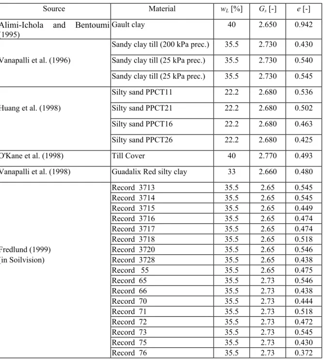
Table 2. Nature, origin, and basic geotechnical properties of the plastic/cohesive materials.
Source Material wL [%] Gs [-] e [-]
Alimi-Ichola and Bentoumi
(1995)
Gault clay 40 2.650 0.942
Sandy clay till (200 kPa prec.) 35.5 2.730 0.430 Vanapalli et al. (1996) Sandy clay till (25 kPa prec.) 35.5 2.730 0.540 Sandy clay till (25 kPa prec.) 35.5 2.730 0.545 Silty sand PPCT11 22.2 2.680 0.536 Huang et al. (1998) Silty sand PPCT21 22.2 2.680 0.502 Silty sand PPCT16 22.2 2.680 0.463 Silty sand PPCT26 22.2 2.680 0.425 O'Kane et al. (1998) Till Cover 40 2.770 0.493 Vanapalli et al. (1998) Guadalix Red silty clay 33 2.660 0.480 Record 3713 35.5 2.65 0.545 Record 3714 35.5 2.65 0.545 Record 3715 35.5 2.65 0.449 Record 3716 35.5 2.65 0.474 Record 3717 35.5 2.65 0.474 Record 3718 35.5 2.65 0.518 Fredlund (1999) Record 3720 35.5 2.65 0.546 (in Soilvision) Record 3728 35.5 2.65 0.438
Record 55 35.5 2.65 0.475 Record 65 35.5 2.73 0.546 Record 66 35.5 2.73 0.438 Record 70 35.5 2.73 0.444 Record 71 35.5 2.73 0.518 Record 72 35.5 2.73 0.472 Record 73 35.5 2.73 0.545 Record 75 35.5 2.73 0.430 Record 76 35.5 2.73 0.372
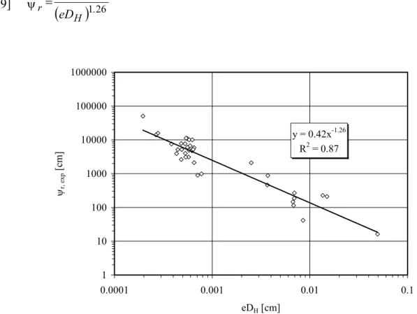
After considering various geotechnical parameters (alone or combined) with a physical significance, it was established that the following relationship provides an adequate estimate of the residual suction (see Figure 6).
[19]
(
)
126 42 0 . H r eD . = ψ y = 0.42x-1.26 R2 = 0.87 1 10 100 1000 10000 100000 1000000 0.0001 0.001 0.01 0.1 eDH [cm] ψr, exp [cm]Figure 6. Relationship between the residual suction ψr,,exp determined from the experimental data
(with best fit WRC), the void ratio e, and the equivalent grain size diameter DH for granular
materials identified in Table 1 (DH is defined by equations 5 and 6).
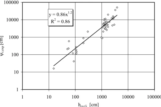
Based on this expression and on equation 7, the authors also developed a simple relationship between ψr and the equivalent capillary rise hco,G for granular materials, which is expressed as
y = 0.86x1.2 R2 = 0.86 1 10 100 1000 10000 100000 1 10 100 1000 10000 100000 hco,G [cm] ψr,exp [cm]
Figure 7. Relationship between the residual suction ψr,,exp determined from the measured data
(and best fit WRC), and the equivalent capillary rise hco,G (eq. 7) for granular materials.
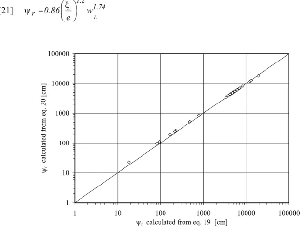
The validity of this equation is confirmed by Figure 8, which shows that equations 19 and 20 give identical residual suction values.
The basic expression obtained for granular soils (eq. 19) is frequently impractical for clayey soils, because D10 and CU are often unknown. Furthermore, the WRC of plastic/cohesive materials is
rarely bilinear (around the residual water content) in a semi-log plot, for suction above the air entry value. Considering also that the experimental results are not customarily available at high suctions, it can be argued that the change in the slope on the WRC that indicates the residual suction is generally not well defined (see also discussion by Corey 1994). The graphical determination of the residual suction ψr thus becomes very difficult for these soils.
In the following applications of the MK model, it is assumed that the residual suction values ψr
for plastic/cohesive soils can be related to the equivalent capillary rise hco,P (equation 11) using
the same dependency as for granular soils. Hence, the expression used for ψr of clayey soils
[21] 1.74 2 . 1 r 0.86 e wL = ξ ψ 1 10 100 1000 10000 100000 1 10 100 1000 10000 100000
ψr calculated from eq. 19 [cm]
ψr
calculated from eq. 20 [cm]
Figure 8. Comparison of the ψr values obtained from equations 19 (see Figure 6) and 20 (see
Figure 7) for the granular materials identified in Table 1.
4.2 Parameter ac and m
Once ψr was determined for each material in the data base (see Table 1 and 2), the remaining
open parameters (ac and m) value was evaluated from a fitting procedure, so that calculated WRC
match experimental data as closely as possible (with the MK model). After repeating the regression calculation for the various results on different materials, further investigations have been conducted to relate the obtained parameter values to basic geotechnical properties. For
introduced parameter is closely related to the grain size distribution. For these same granular materials, the analysis indicated that the adhesion coefficient ac is approximately constant, with ac= 0.01.
For the plastic/cohesive soils considered here, with hco,P given by equation 11, both m and ac
values can be taken as constants (with m = 3x10⁻⁵ and ac = 7x10⁻⁴) in the predictive applications.
In this case, the influence of grain-size distribution is somewhat superseded by the dominant effect of the surface activity (defined here through the wL function).
The relationships and parameter values defined for the MK model can now be used to evaluate the WRC of various materials. Tables A-1 and A-2, in Appendix, give sample results to show explicitly how the presented set of equations are used to obtain the WRC. Figures 9 to 15 compare typical fitted (with adjusted ac and m values) and predicted (with preset ac and m values)
curves using the experimental data obtained for different granular and clayey materials. Identification and basic properties (D10, Cu and e for granular materials; wL, e and ρs for
plastic/cohesive soils) are given in each figure. The value of ac and m that leads to the best fit
curves shown in Figure 9 to 15 are given in Table 3. As can be seen on these figures, there is generally a good agreement between the predicted and the measured WRC, despite the differences sometimes observed between the best fit and predicted parameter values (especially with m for loose or clayey materials ). Such good agreement is obtained with most of the results identified in Tables 1 and 2. In fact, the predictions made with the MK model compare favorably to those obtained with most other models, which often include more input parameters (and thus require more information for their application), as depicted in recent review publications (e.g. Wösten et al. 2001; Schaap et al. 2001; Rawls et al. 2001; Zhuang et al. 2001). For instance, predicted volumetric water content values, at a given suction, generally approach the measured values within a range of 0.02 to 0.05, which is comparable to the best available pedotransfer functions, that often relies on particular measured points on the WRC (i.e. water content at suctions of 10, 33, or 1500 kPa for instance). It must be said however that the authors have concentrated most of their efforts on the practical development of the model equations for geotechnical applications, than on statistical analyses of the MK model capabilities (and on systematic comparison with other available functions). More work on this aspect will have to be
performed in the future. In the meantime, the proposed set of equations has been successfully used by the authors on actual field projects (e.g. Aubertin et al. 1999; Nastev and Aubertin 2000), and also by others on different types of particulate media (outside the authors’ data bank). The success obtained so far are due, in part, to the sound physical description of the WRC provided by the MK model.
There are nevertheless some discrepancies between the predicted curves and actual data. Some aspects related to these differences are discussed below, together with other features, capabilities, and limitations of the MK model.
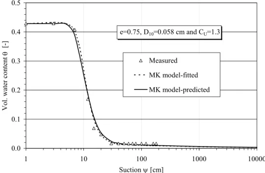
e=0.75, D10=0.058 cm and CU=1.3 0.0 0.1 0.2 0.3 0.4 0.5 1 10 100 1000 10000 Suction ψ [cm]
Vol. water content
θ [-]
Measured MK model-fitted MK model-predicted
Figure 9 . Application of the MK model to a coarse, uniform, and relatively loose sand (data from Sydor 1992).
e=0.267, D10=0.009cm, and CU=2.6 0.00 0.05 0.10 0.15 0.20 0.25 1 10 100 1000 10000 100000 1000000 10000000 Suction ψ [cm]
Vol. water content
θ [-]
Measured
MK model-best fit Mk model -predicted
Figure 10. Application of the MK model to a fine, uniform, and dense sand (data from Bruch 1993). e=0.72, D10=0.0004cm et CU=9.8 0.00 0.05 0.10 0.15 0.20 0.25 0.30 0.35 0.40 0.45 1 10 100 1000 10000 100000 1000000 10000000 Suction ψ [cm ]
Vol. water content
θ [-] Measured
MK model-best fitted MK model-predicted
Figure 11. Application of the MK model to tailings Sigma (silty material, well-graded, and loose) (data from authors).
0.00 0.10 0.20 0.30 0.40 0.50 0.60 1 10 100 1000 10000 100000 1000000 10000000 Suction ψ [cm ]
Vol. water content
θ
[-]
Measured
MK model - best fitted MK model - predicted
e=0.944, D10=0.0001 cm, CU=35
Figure 12. Application of the MK model to tailings Sigma mixed with 10 % bentonite (data from authors). e=0.48, wL=33% and ρs =2660kg/m3 0.0 0.1 0.2 0.3 0.4 1 10 100 1000 10000 100000 1000000 10000000 Suction ψ [cm]
Vol. water content
θ [-]
Measured MK model-fitted MK model - predicted
e=0.493, wL=40% and ρs=2770kg/m3 0.0 0.1 0.2 0.3 0.4 1 10 100 1000 10000 100000 1000000 10000000 Suction ψ [cm]
Vol. water content
θ [-]
Measured MK model - fitted MK model - predicted
Figure 14.Application of the MK model to a till (data from O’Kane et al. 1998)
e=0.438, wL=35.5 % and ρs=2650 kg/m3 0.0 0.1 0.2 0.3 0.4 1 10 100 1000 10000 100000 1000000 10000000 Suction ψ [cm]
Vol. water content
θ [-]
Measured MK model -fitted MK model - predicted
Table 3. Parameters m and ac leading to the best fit WRC shown in Figures 9 to 15, and the
empirically determined values.
Fitted WRC Predicted WRC
Material m ac m ac
Coarse, uniform and relatively dense sand (data from Sydor 1992), see Figure 9
0.827 0.007 0.769 0.01
Fine and dense sand (data from Bruch 1993), see Figure 10
0.091 0.013 0.388 0.01
Tailings Sigma (silty material, coarse and loose) (Authors data), see Figure 11
0.161 0.010 0.102 0.01
Tailings Sigma mixed with 10% bentonite (Ricard 1994), see Figure 12
0.019 0.009 0.029 0.01
Guadalix Red silty clay (data from Vanapalli et al. 1998), see Figure 13
3.6x10⁻⁶ 7.6x10⁻⁴ 3.0x10⁻⁵ 7.0x10⁻⁴
Till (data from O’Kane et al. 1998), see Figure 14
8.1x10⁻⁶ 6.5x10⁻⁴ 3.0x10⁻⁵ 7.0x10⁻⁴
Indian Head Till (Record 728; data from Fredlund 1999), see Figure 15
1.0x10⁻⁹ 7.0x10⁻⁴ 3.0x10⁻⁵ 7.0x10⁻⁴
5. DISCUSSION
The proposed functions presented above provide a simple means to estimate the WRC for granular and plastic/cohesive soils, as well as for other particulate media. The MK model equations have been developed as an extension of the Kovács’ (1981) model, which was selected
components for predictive purposes requires only basic geotechnical properties such as the grain size (through D10, CU), porosity n (or void ratio e), solid grain density (ρs), and liquid limit (wL).
When analyzing the quality of predictions made with the MK model and the discrepancies sometimes observed, one should take into account the variety of the WRC measurement techniques and the associated uncertainties and limitations. These may have a significant effect on the curves and on the estimates for parameters ψr, m, and ac in the MK model. In that regard,
it can be expected that the quality of the predictions is influenced by the data themselves. Despite this situation, the accordance between predicted and measured WRC is generally good, and the results can be used for preliminary analysis. The proposed model however shows some limitations in its predictive capabilities. Some of these are discussed in the following.
5.1 Prediction of the residual suction and air entry value
The residual suction ψr and the air entry value ψa (or AEV) are familiar points defined on the
WRC, that are often used for practical applications. The residual suction ψr has already been
defined above with the MK model. However, the actual value of this suction (and of the corresponding volumetric water content) is difficult to determine precisely, and even its physical meaning has been questioned (e.g. Corey 1994). For the applications shown here, there is more than one approach that can be used to define ψr. It can be measured on the fitted curves for the
available experimental data (with MK, or with other models such as the van Genuchten 1980 equation used in the preliminary phase of the model development); it corresponds to the intersection point between two tangents (see Fig. 1a). It can also be evaluated on the predicted WRC. When the best fit and predicted curves are close to each other (like in Figure 9), the residual suctions obtained from the two approaches are then almost identical, and correspond well to the value predicted by equation 19. However, when the best fit and predicted curves differ (like in Figure 10 and 12), the residual suction can then take fairly different values depending on the way it is determined.
For the MK model application, equation 19 is used to define suction ψr, which is then used in the
WRC construction from the set of equations (eq. 14 to 18). This means that the predicted ψr
(from eq. 19) may be somewhat different than the one deduced from the complete WRC obtained from the model. Furthermore, strictly speaking according to the MK model (for the best fit or predicted WRC), residual suction is reached only when the capillary component Sc goes to
(almost) zero, but this condition is not exactly equal to the intersection point between the two tangents. Hence, at this point, one must infer that this specific state can only be approximated with the predictive tools at hand.
A somewhat similar situation can be described for the air entry value. The AEV can also be estimated with the set of equations proposed above. However, more than one method exists to determine the AEV (e.g. Corey, 1994; Fredlund and Xing, 1994; Aubertin et al. 1998), so different values may be obtained for a given information. Furthermore, because the MK model aims at describing the entire WRC, it is not particularly efficient in defining precisely specific points on the curve, such as the AEV. Hence, in this case, one may need to make some adjustments to better reflect the observed ψa; the adjustments to the predicted curves may be
especially significant for loose (compressible) materials. Fortunately, the ψa determined from
actual experimental data (ψa,exp), can be related to values obtained from the WRC predicted by
the MK model (ψa,MK). A relationship for that purpose is shown in Figure 16. Values ψa,exp and
ψa,MK were determined using the tangent method (see Figure 1). The curves used to determine
ψa,exp were obtained by fitting the experimental data with a descriptive equation; again the van
Genuchten (1980) model was used (N.B. fitted curves with MK would provide essentially the same AEV) ). The relationship presented in Figure 16 indicates that the MK model tends to overpredict ψa. A correction factor of 0.83 nevertheless allows a fairly good representation of the
ψa,exp = 0.83ψa,MK R2 = 0.85 1 10 100 1000 1 10 100 1000 ψa,MK [cm] ψa,exp [cm]
Figure 16. Comparison between the air entry values obtained from the experimental data ψa,exp
(with best fit WRC) and obtained on the WRC predicted by the MK model (ψa,MK) for granular
materials.
One can also estimate the experimental AEV using instead some basic geotechnical properties. Various specific relationships have been proposed for that purpose (e.g. Palubarinova-Kochina 1962; Bear 1972; Yanful 1991). According to the authors’ own analyses, the AEV obtained with most existing functions tend to agree with each other for coarse grained materials such as sands, but significantly diverge for fine grained materials (Aubertin et al. 1993). A recent investigation by the authors to develop a more representative relationship for granular materials has lead to the following expression (see Figure 17):
[22] 1 1 x H . est , a ) eD ( b = ψ
where b1 and x1 are fitting parameters and DH has been given above in equations 6-8 (i.e.
DH=[1+1.17log(CU)]D10). As can be seen in Figure 17, almost similar predictions (for the range
equation 22. In this equation, the estimated ψa is related explicitly to e, D10, and CU as was
suggested by Aubertin et al. (1998).
ψa,est = 0.43(eDH)-0.84 R2 = 0.84 1 10 100 1000 0.00001 0.0001 0.001 0.01 0.1 eDH [cm] ψa,exp [cm] ψa,est=0.15/(eDH)
Figure 17. Proposed relationships for estimating the air entry value ψa,exp obtained on the
experimental data for granular materials.
Equation 22 can also be used to estimate the air entry values deduced from the WRC predicted by the MK model (i.e. ψa,MK, with b1 = 0.6, x1 = 0.8 -see Figure 18). These simple relationships can
be used to make a correction of the AEV obtained from the MK model, to better reflect the actual measured ψa. Hence, this allows the user to improve upon the prediction of this particular
ψa,MK = 0.60(eDH)-0.80 R2 = 0.97 1 10 100 1000 0.0001 0.001 0.01 0.1 eDH [cm] ψa,MK [cm]
Figure 18. Proposed relationship for estimating the air entry value ψa,MK obtained on the WRC
predicted by the MK model for granular materials.
Also, it was suggested also by the authors (Aubertin et al. 1998) that the AEV could be defined from the suction corresponding to a given degree of saturation Sr. Figure 1 shows two such
conditions for Sr equal to 90% and 95%. The predicted air entry value ψa,MK is compared to
calculated suctions corresponding respectively these two degrees of saturation (which do not require extrapolation or any interpretation of the WRC). Figure 19 shows that there is a systematic relationship between ψa,MK and ψ95,MK and ψ90,MK. These results, combined with
Figure 16, indicate that the experimental ψa,exp can be related to the latter two parameters (ex.
ψa,exp = 0.83ψa,MK =0.83x0.89ψ95,MK =0.74ψ95,MK). This in good agreement with previous
analyses with other curve fitting equations (of Brooks and Corey 1964 and van Genuchten 1980), which have indicated that the rather steep curvature around the AEV induced by the Kovács and MK models typically tends to overestimate the actual AEV (Aubertin et al. 1998). If a rather conservative approach is required for a given project (i.e. underestimation of the AEV is favored), the authors suggest using ψa equal to about 0.6 ψ90,MK, or 0.74 ψ95,MK obtained on the
ψa.M K = 0.72ψ90,M K R2 = 0.93 ψa,M K = 0.89ψ95,M K R2 = 0.97 0 200 400 600 800 0 200 400 600 800 ψ90,ΜΚ and ψ95,ΜΚ [cm ] a-MK [cm] ψ90,M K ψ95,M K
Figure 19. Relationships between the predicted air entry value ψa,MK and suctions ψ90,MK and
ψ95,MK corresponding respectively to degrees of saturation of 90% and 95%, (obtained on the
WRC predicted by the MK model) for granular materials.
Finally on this issue, the authors have not yet been successful at developing an acceptable correlation between ψa and basic geotechnical properties for plastic/coherent materials (mainly
because of the paucity of available results). The potential user should thus be careful when using the MK model for that purpose, in the absence of an independent validation relationship. The approach presented above, associating the AEV and the suction at Sr=0.95 or 0.90 in the MK
model, may still be applicable in this case, but too few data have been analyzed at this stage to confirm their validity.
the pore diameter deq lies between the limiting values (minimal and maximal diameter) of the
pore size distribution, to which a maximum (hcmax) and minimum (hcmin) capillary rise can be
associated, it is be expected that hco should lie between hcmax and hcmin.
Because water can only be retained by adhesion forces above hcmax, this elevation could thus be
associated to the residual suction ψr defined on the drainage water retention curve (e.g. Lambe
and Whitman 1979). Therefore, one should observe that hco ≤ ψr. This is in agreement with the
relationship between ψr and hco given by equation 20. On the other hand, the minimum capillary
rise hcmin can be associated the air entry value ψa. As shown on Figure 20 for granular materials,
the equivalent capillary rise hco,G and the air entry value can be correlated by the following
expression: [23] 2 2 ax G , co b h = ψ
From the available data, the authors have obtained b2 ≈ 5.3 and x2 ≈ 1 when ψa is determined
from the experimental curve (ψa,exp), and b2 ≈ 1.7 and x2 ≈ 1.2 when ψa is given by the MK
predictive model (ψa,MK) at full saturation (see Figure 1). As mentioned before, these
relationships indicate that the equivalent capillary rise hco is much larger than the air entry value,
which corresponds more or less to the height of the capillary fringe in a homogeneous deposit.
With the MK model, the equivalent capillary rise hco has been defined with a theoretical function
of the specific surface area Sm, a property that is rarely evaluated precisely. Because Sm can vary
over a wide range (from less than 10 m2/g to more than 600 m2/g for various soils; e.g. Marshall et al. 1996), the proportionality between hco and Sm has a major influence on the estimation of hco.
In particular, for clayey soils, it has been postulated that the specific surface can be related explicitly to the liquid limit wL, which only reflects indirectly the surface characteristics of soils.
The MK model application presented here thus introduces Sm in a relatively crude (but practical)
manner, and this approach can induce a relatively large uncertainty on the value of hco. That is
why this parameter should be viewed as a semi-empirical component introduced in an otherwise physically based model; such pragmatic simplification is very useful for engineering applications.
hco,G = 1.7ψa,MK1.21 R2 = 0.97 hco,G = 5.3ψa,exp0.99 R2 = 0.84 1 10 100 1000 10000 1 10 100 1000 10000 ψa [cm] hco,G [cm] ψa,exp ψa,MK
Figure 20. Relationships between the equivalent capillary rise hco,G and the air entry value for
granular materials; ψa,exp and ψa,MK are obtained on the experimental and on the MK model
predicted WRC respectively.
5.3 Parameters with preset values
In the above applications, values have been pre-assigned to the adhesion coefficient ac (0.01 in
the case of granular materials for wL below about 30 to 40%, and 7x10⁻⁴ in the case of
plastic/cohesive materials). When the MK model is adjusted to all the experimental WRC considered in this study, the actual value of ac leading to best fit curves is not constant but rather
varies from 0.001 to 0.024 for granular materials and from 6x10⁻⁴ to 9x10⁻⁴ for clayey soils. Thus, the actual deviation on ac is fairly high, being above one order of magnitude for granular