HAL Id: hal-03155792
https://hal.archives-ouvertes.fr/hal-03155792
Submitted on 2 Mar 2021HAL is a multi-disciplinary open access archive for the deposit and dissemination of sci-entific research documents, whether they are pub-lished or not. The documents may come from teaching and research institutions in France or abroad, or from public or private research centers.
L’archive ouverte pluridisciplinaire HAL, est destinée au dépôt et à la diffusion de documents scientifiques de niveau recherche, publiés ou non, émanant des établissements d’enseignement et de recherche français ou étrangers, des laboratoires publics ou privés.
Catalytic methane combustion in plate-type
microreactors with different channel configurations: An
experimental study
Li He, Yilin Fan, Jérôme Bellettre, Jun Yue, Lingai Luo
To cite this version:
Li He, Yilin Fan, Jérôme Bellettre, Jun Yue, Lingai Luo. Catalytic methane combustion in plate-type microreactors with different channel configurations: An experimental study. Chemical Engineering Science, Elsevier, 2021, 236, pp.116517. �10.1016/j.ces.2021.116517�. �hal-03155792�
* Corresponding authors.
Email addresses: [email protected] (J. Yue), [email protected] (L.Luo) 1
He, L., Fan, Y., Bellettre, J., Yue, J., & Luo L. (2021). Catalytic methane combustion in plate-type
1
microreactors with different channel configurations: an experimental study. Chemical Engineering
2
Science, 236, 116517. https://doi.org/10.1016/j.ces.2021.116517
3 4 5
Catalytic methane combustion in plate-type microreactors with different
6
channel configurations: an experimental study
7
Li He a, b, Yilin Fan a, Jérôme Bellettre a, Jun Yue b, *, Lingai Luo a, *
8
a Université de Nantes, CNRS, Laboratoire de thermique et énergie de Nantes, LTeN, UMR 6607,
9
F-44000 Nantes, France
10
b Department of Chemical Engineering, Engineering and Technology Institute Groningen,
11
University of Groningen, 9747 AG Groningen, The Netherlands
12 13
ABSTRACT:
14
This paper presents an experimental study on the catalytic methane combustion (CMC) in plate-15
type microreactors with wall-coated Pt/γ-Al2O3 catalyst. Firstly, the influence of different
16
operational conditions and coating properties on the CMC in the straight parallel-channel 17
microreactor has been investigated. A specific catalyst loading of 57.6 g m-2 was found to yield
18
the highest methane conversion over 3.5 wt% Pt/γ-Al2O3. A higher or lower loading tended to
19
decrease the methane conversion due to either the limited internal diffusion through the thicker 20
coating layer or insufficient active sites in the thinner coating layer. Then, the above microreactor 21
was compared with other five different geometries, including cavity, double serpentine 22
microchannels, obstacled microchannels, meshed circuit and vascular network. The double 23
serpentine microchannel geometry presented the highest methane conversion (especially at a 24
2
relatively low mixture flow rate) due to the appropriate control over the residence time and 1
catalyst coating surface area. 2
3
Keywords: Catalytic methane combustion; microreactor; washcoated catalyst; channel
4
configuration; methane conversion; flow distribution 5
6
Nomenclature
7
A Total cross-sectional area of the reaction microchannel in a microreactor,
m2
𝐹𝐹𝐶𝐶𝐶𝐶4,𝑖𝑖 Inlet molar flow rate of CH4, mol s-1
𝐹𝐹𝐶𝐶𝐶𝐶4,𝑜𝑜 Outlet molar flow rate of CH4, mol s-1
𝐹𝐹𝐶𝐶𝐶𝐶𝑥𝑥,𝑜𝑜 Outlet molar flow rate of CO or CO2, mol s-1
𝐹𝐹𝐶𝐶2,𝑜𝑜 Outlet molar flow rate of H2, mol s-1
h Channel height, m
lj,tot Total channel length between bifurcation indices j and j+1, m
lj,1 Length of horizontal channel at the index j in the tree-like bifurcated
structure, m
Qtot Total volumetric flow rate, m3 s-1
r Ratio of channel width of the downstream to that of the upstream in one
bifurcation, -
S Inner surface area of microchannels subjected to Pt/γ-Al2O3 coating, m2
𝑆𝑆𝐶𝐶2 Selectivity of H2, %
𝑆𝑆𝐶𝐶𝐶𝐶𝑥𝑥 Selectivity of CO or CO2, %
3
Vtot Total microchannel volume for reaction in a microreactor, m3
Wcat Catalyst mass, g
wj Channel width at the index j in the tree-like bifurcated structure, m
𝑋𝑋𝐶𝐶𝐶𝐶4 CH4 conversion, %
Greek symbols
1
𝜏𝜏 Mean residence time, s
Φ Inlet molar ratio of oxygen to methane, -
𝜑𝜑 Specific catalyst loading, g m-2
𝜇𝜇 Dynamic viscosity, Pa s
𝜌𝜌 Density, kg m-3
Abbreviation
2
CMC Catalytic methane combustion
GC Gas chromatography
i.d. Inner diameter
MW Molecular weight
o.d. Outer diameter
PVA Polyvinyl alcohol
3
1. Introduction
4
Natural gas has been reported to have a largest increment in consumption in the past decade, 5
accounting for nearly half of the increase in global energy demand in year 2018 [1-3]. The 6
combustion of natural gas presents a particular advantage of higher energy content per CO2
7
emission (55.7 kJ g-1 if fully based on methane as its main component) than coal (39.3 kJ g-1)
8
and petroleum (43.6 kJ g-1), a character which is essential to a low carbon future. In addition to
9
the abundant natural gas reserves proven worldwide, biomethane could be obtained from organic 10
4
wastes and residues by biomass gasification/digestion [4,5], providing a competitive energy 1
supply towards a more electrified world [3]. As a result, natural gas has been suggested as a 2
substitute for oil and coal as a future leading energy source for the next 20 years [3,6]. According 3
to the International Renewable Energy Agency (IRENA) [6], the utilization of petroleum and 4
coal would decline by 70% and 85%, respectively, by 2050, whereas natural gas would be the 5
largest source by then and achieve peak on its utilization at around 2027 [6]. Thus, a great number 6
of researches have been devoted to the development of energy-efficient natural gas combustion 7
systems in many aspects for their application in the industrial, transport and domestic areas, etc. 8
[7]. 9
10
However, the gas industry faces some commercial and environmental challenges [5], due to the 11
releasing of pollutant emissions (e.g., NOx, CO and unburned hydrocarbon) by the conventional
12
flame combustion of methane typically occurring at above 1400 oC. The harmful impacts of these
13
emissions on the human health and environment have been well recognized [8] and the 14
applicable regulations over EU countries have become more and more stringent in recent years 15
[9]. In this context, the catalytic methane combustion (CMC) as a promising alternative has 16
received increasing attention [10]. A lower working temperature (e.g., < 600 °C) is needed for 17
the complete oxidation of methane in the presence of catalyst because of the reduced activation 18
energy (40-80 kJ mol-1) compared to that for conventional combustion (100-200 kJ mol-1).
19
Hence, the exhaust emissions (especially of NOx) can be remarkably abated [7,10-12]. Abundant
20
literature is available on the CMC, as summarized by recently published review papers [10,13-21
15]. These existing CMC studies distinguish themselves by focusing on the catalyst development 22
[16-19] and mechanisms [20-24], different types of catalytic reactors [25-29] and (optimized) 23
reaction conditions [30-33], as well as the target applications [29,34,35]. 24
5
Various types of catalysts have been studied for the CMC including noble metal catalysts and 1
mixed oxides catalysts (perovskites and hexaaluminate) [10,36,37]. Among them, noble metal 2
catalysts (e.g., Pt, Pd, Rh) are the most commonly used and well developed owing to their high 3
specific surface area, high catalytic activity and low light-off temperature [30,38]. Bimetallic 4
catalysts (e.g., Pd-Pt/Al2O3) often show higher catalytic activity and selectivity than their
5
monometallic counterparts due to the synergistic effect by metal-metal interaction [39,40]. 6
Additionally, different supports and additives (e.g., ZrO2, CeO2 [41,42]) have been introduced
7
to improve the catalytic activity through the acceleration of oxygen exchange. In terms of the 8
catalyst form, washcoated catalysts have undergone rapid development in recent years. The 9
washcoated catalyst is commonly deposited as a thin layer on structured surfaces of monolithic 10
reactors or (multichannel) microreactors, in order to avoid the high pressure drop and large 11
temperature gradient likely existing in conventional fixed/packed bed reactors loaded with 12
catalyst powders or pellets [27]. In this regard, the good adhesion and coverage of the coated 13
catalyst layer on the channel walls are essential for the CMC performance of the reactor. The 14
suspension method [43-46] and sol-gel method [47,48] are most commonly used for 15
washcoating. It has been reported that the preparation method, binder nature, pH value and 16
particle size could be the key factors that have to be adapted to obtain a high thermal stability 17
and a uniform coverage of the coating [46]. 18
19
Fixed/packed-bed reactor (catalysts typically in the form of fine powder) is conventionally 20
employed for the research of the catalyst activity and reaction mechanism due to the easy 21
operation and enhanced catalyst spatial density. Nevertheless, the low surface area, poor 22
temperature uniformity and relatively high pressure drop are main disadvantages of the 23
conventional fixed-bed reactor [15]. As an interesting alternative, the microreactors present a 24
high surface-to-volume ratio, relatively low pressure drop, and high mass/heat transfer rate 25
(especially when combining with washcoat catalyst), which is beneficial to prevent the catalyst 26
6
sintering in the long term due to the better temperature regulation. As more attention has been 1
paid on the research of microreactor, it could become a promising candidate for potential 2
industrial applications. In particular, plate-type microreactors containing a multitude of 3
microchannels arranged in parallel have attracted great interests [49,50]. In combination with the 4
well-adhered catalyst coating on the wall surface, the plate-type multichannel microreactors offer 5
numerous advantages, including the compact design, easy to manufacture and the scaling-up 6
potential to handle a large amount of reactive gas [51,52]. These features are especially beneficial 7
for handling the CMC or highly exothermic reactions in general by suppressing the presence of 8
temperature hot spots due to the local accumulation of reaction heat [53-55]. For instance, the 9
experimental study by O’Connell et al. [27] shows that a 100 % conversion could be obtained in 10
a multichannel microreactor (500 μm width × 250 μm depth, 14 channels in total) washcoated 11
with Pt-W or Pt-Mo/γ-Al2O3 catalyst at 600 oC and a total gas flow rate of 107 mL min-1 (space
12
velocity of 74,000 h-1) and an O2/CH4 molar ratio of 2.2. He et al. [46] experimentally performed
13
the CMC in a multichannel reactor (275 mm length × 1.5 width mm × 1 mm height, 32 channels 14
in total) over the washcoated Pt/γ-Al2O3 catalyst. A 95.75 % methane conversion was obtained
15
at 450 oC under a total gas flow rate of 110 mL min-1 (space velocity: 6,557 h-1) and an O
2/CH4
16
molar ratio of 2. Moreover, the compact and modular feature of the plate-type multichannel 17
microreactor makes it possible for a better utilization of the reaction heat [56,57]. The 18
development of the so-called autothermal reactor that combines the CMC (exothermic reaction) 19
with another endothermic reaction (e.g., methane steam reforming to produce hydrogen or 20
syngas) within a single device has become a research hotspot over the past decade [58]. 21
Mundhwa et al. [56,57] proposed a stacked autothermal reactor design which was composed of 22
two plates with parallel microchannels (5 cm length × 1 mm width, 15 channels, coated with ca. 23
20 μm thick Pt/Al2O3 catalyst) for the CMC and other two plates of cavity shape (5 cm length ×
24
5 cm width × 100 μm depth, with washcoated Ni/Al2O3 catalyst) for the methane steam reforming
25
reaction. Their numerical results show that this compact multiple plate design (especially under 26
7
the co-current mode between flows) could reduce the required amount of catalyst for the CMC 1
by 70% and maintain a uniform temperature profile for the methane steam reforming [56,57]. 2
The scale-out strategy of microreactor stacks has been investigated numerically for coupling 3
such exothermic and endothermic processes [59]. The results illustrate that a certain number of 4
stacks (e.g., > 15) was needed so that the released reaction heat could compensate for the heat 5
loss and thus drive the reforming reaction effectively [59]. 6
7
It is noteworthy that most of the plate-type multichannel microreactors tested for the CMC or 8
simulated for its autothermal coupling have a simple configuration like parallel straight channels 9
[27,46,56-60]. In this respect, the influence of the operating parameters and the washcoated 10
catalyst properties (e.g., of the promising noble metal-based one) on the CMC performance still 11
needs more systematic investigations, as the current understanding is still far from being 12
sufficient. Furthermore, in order to provide an effective way to realize the miniaturization, the 13
design and optimization of microchannel geometries deserve particular attention. On one hand, 14
the improved the mixing and the enhanced the mass/heat transfer of appropriate microchannel 15
configurations (compared to parallel straight channel) will render better reactor performance so 16
that the (nearly) 100 % methane conversion could be achieved at a lower temperature or with a 17
lower needed amount of catalysts. The lifetime of noble metal catalysts could be prolonged for 18
a higher cost-effectiveness of the CMC technology. On the other hand, the better thermal 19
management of this strong exothermic reaction achieved by optimizing the reaction channel 20
configuration will facilitate the design of the associated cooling system, which is especially 21
beneficial for various aimed applications such as autothermal reactor and CMC boiler. However, 22
the testing and comparison of different microchannel geometries on the CMC performance have 23
been rarely reported in the literature. There is still much room for the reactor performance 24
improvement by optimizing the internal microchannel configurations that lead to a better process 25
control (e.g., narrowed residence time distribution and more uniform reactant flow distribution) 26
8
and catalyst utilization (e.g., high catalyst surface area and improved gas-solid mass transfer) in 1
the CMC. Such microreactor performance optimization is equally important towards obtaining 2
a better usage of the released reaction heat from the CMC in energy applications, such as the 3
small-scale water boiler and the autothermal reaction device. 4
5
As a continuation of our previous study [46], this work has firstly presented an experimental 6
investigation into the CMC performance over the microreactor with parallel straight channels 7
coated with Pt/γ-Al2O3 catalyst. The influence of different operation conditions (e.g.,
8
temperature, flow rate and oxygen to methane molar ratio), catalyst loading and thickness, 9
reaction microchannel length was studied. Then, the reaction performance of this type of 10
microreactor was compared with those of other five type of microreactors with different channel 11
configurations. The studied configurations cover some relatively simple channel geometries 12
(cavity and double serpentine microchannels) and more complicated ones (obstacled 13
microchannels, meshed circuit and vascular network). The methane conversion between 14
different microreactor designs has been compared and explained based on the internal channel 15
surface area, residence time and the specific catalyst loading. Moreover, the use of tree-like 16
bifurcation structure for fluid distribution or collection in the microreactor was explored towards 17
improved reaction performance. The findings of this work may help to achieve a flexible and 18
compact design of microreactors that allows upscaling from laboratory to field-scale applications 19
of the CMC with optimized performance. 20
21
2. Experimental
22
2.1. Experimental setup and procedures
23
The experimental test rig is shown in Fig. 1. Two mass flow controllers (MFC, Brooks SLA5850) 24
were used to adjust the flow rates of methane and the synthetic air for the CMC experiment. The 25
total gas flow rate was adjusted from 110 to 500 mL min-1 (based on ca. 20 oC and 1 atm).
9 1
For each test, the oven (Nabertherm, LT 9/11/B170) was firstly heated up to the target 2
temperature at a ramp of ca. 15 oC min-1 flowing with air to prevent any reaction happened during
3
heating up process. Once the oven temperature reached the target reaction temperature ranging 4
between 300 oC and 500 oC, the methane-air gas mixture (at an O2/CH4 molar ratio from 0.5 to
5
6) first passed through the inlet pre-heating coil (stainless steel; i.d.: 3.7 mm, o.d.: 6 mm, ca. 20 6
cm in length) in the oven, and was then introduced into the plate-type microreactor where the 7
catalytic reaction happened. The product gas first flew out through a condenser to remove water, 8
and was then analyzed by an online gas chromatography (GC). 9
10
Fig. 1. Test rig for the CMC in the plate-type microreactor.
11 12
2.2. Reactor design and fabrication
13
The plate-type microreactor has an overall dimension of 190 mm in length, 130 mm in width and 14
10 mm in height. It was designed as a sandwich shape with a reaction plate (made of FeCrAlloy, 15
i.e., Kanthal A-1, 22 % Cr, 5.8 % Al and Fe for balance) in the middle, enclosed by two additional 16
blind plates (made of stainless steel) as the outside shell (Fig. 2). One blind plate has additional 17
inlet and outlet ports in order to interface with the reaction platelet (vide infra). A graphite gasket 18
(3 mm in thickness) was installed in between these plates to prevent the gas leakage and bolts 19
were used on the peripherals for further sealing. A liquid leak detector (Snoop) was applied on 20
the assembled microreactor in order to ensure the tightness before each series of the test. 21
10 1
The middle reaction plates have an overall dimension of 112.5 mm (length) × 50 mm (width) × 2
3 mm (height). Each plate has a single inlet port and outlet port (i.d.: 6.5 mm) aligned with the 3
central line, the distance between their centers being 82.5 mm. Six shapes of the internal flow 4
network have been designed and machined on one side of the plate, all of them having a 5
symmetric geometry, as shown in Fig. 2. Each flow network consists of three parts: the inlet 6
distributor, reaction microchannel(s) subjected to the catalyst coating (on two sides and the 7
bottom surface of the microchannel wall) and outlet collector. A detailed description of the six 8
reactors (Reactors #1-6) and its flow network is presented as follows. Note that except for the 9
cavity case (Reactor #2), all the reaction microchannels have a rectangular cross-section of 1.5 10
mm in width and 1 mm in height. 11
12
Reactor #1 (denoted as the straight parallel channel microreactor) has a basic shape of 16 13
parallelized and straight reaction microchannels of 60 mm in length. The thickness of the 14
separating walls between neighbouring microchannels is 1.5 mm. 15
16
Reactor #2 (denoted as the cavity microreactor) has a simple cavity geometry for reaction 17
(dimension: 66.45 mm length × 46.5 mm width × 1.0 mm depth). 18
19
Reactor #3 (denoted as the double serpentine channel microreactor) consists of two serpentine 20
reaction microchannels arranged in axial symmetry. For each zigzag unit, the channel length of 21
the horizontal section is 21 mm and that of the vertical section is 4.5 mm, the angle of zigzags 22
being 90 o. The thickness of the separating walls is 1.5 mm. The total length of each serpentine
23
microchannel is 547.02 mm. 24
11
Reactor #4 (denoted as the obstacled parallel channel microreactor) differs from the basic straight 1
parallel channel microreactor (Reactor #1) by the presence of solid obstacles (square shape, 1.5 2
mm × 1.5 mm) along the flow direction in the reaction microchannels. Each microchannel thus 3
assumes a split-and-recombine shape around successive obstacles (4.5 mm × 4.5 mm, 10 pieces 4
for each, 80 in total). The thickness of walls separating the microchannels is 1.5 mm. The 5
connection unit between repeating split-and-recombine units is 1.5 mm in length and 1.5 mm in 6
width. 7
8
Reactor #5 (denoted as the meshed circuit microreactor) presents a meshed flow circuit with 9
channel interlacing, inspired by the land crack architecture in nature [61]. The reaction 10
microchannels are intersected at a crossing angle of 90o. The solid diamond blocks formed
11
between the adjacent microchannels have a dimension of 2.74 mm × 2.74 mm with 143 pieces 12
in total. 13
14
Reactor #6 (denoted as the vascular microreactor) has two vascular blocks arranged in axial 15
symmetry. For each vascular block, there are two side vertical microchannels (69 mm length × 16
1.5 mm width) for gas splitting whereas one central vertical microchannel (66 mm length × 1.5 17
mm width) for recombining. The side and central vertical microchannels are connected by means 18
of short horizontal microchannel sections (9 mm length × 1.5 mm width, 86 pieces in total) that 19
are arranged in a staggered pattern and separated by rectangular parallelepipeds (9 mm in length 20
and 1.5 mm in width). 21
12 1
Fig. 2. Schematics of various plate-type microreactors. Reactors #1-6 denote, respectively, the
2
straight parallel channel microreactor, cavity microreactor, double serpentine channel 3
microreactor, obstacled parallel channel microreactor, meshed circuit microreactor and vascular 4
microreactor. 5
6
The inlet fluid distributor and outlet fluid collector fed with the reaction microchannel(s) also 7
differ to some extent in Reactors #1-6. The combination of a multi-scale bifurcated distributor 8
and a simple rectangular collector was employed for Reactors #1, 2, 4 and 5 (Fig. 2). Regarding 9
Reactors #3 and #6, the above structures are not very appropriate due to the geometrical 10
13
constraints, i.e., the reaction microchannel being either limited in number (only two in Reactor 1
#3) or with a special shape (vascular in Reactor #6). Thus, a simple bilateral divergent or 2
convergent channel network was used as the distributor or collector, respectively. The design, 3
scaling relations and detailed dimensions for these distributors/collectors are found in Appendix 4
A. 5 6
2.3. Catalyst preparation and coating procedures
7
The reaction platelets were first immersed with acetone at 45 oC for 30 min in the ultrasonic bath
8
(PCE-UC 20) with the frequency being 40 kHz, in order to remove oil, grease and other dirt [62]. 9
Thermal pretreatment was subsequently performed at 900 oC (ramp from room temperature: 20
10
oC min-1; 10 h at the final temperature), in order to generate a thin alumina layer over the substrate
11
surface which could be a strong bonding between the Pt/γ-Al2O3 coating layer and the substrate.
12
The slurry suspension method was applied for the coating deposition in microreactors [63,64]. 13
The materials used for preparing the catalytic coating were as follows: γ-Al2O3 (3 µm, 99.97 %
14
on metals basis), PVA (98-99 % hydrolyzed), acetic acid and tetraammineplatinum (II) nitrate 15
(Pt(NH3)4(NO3)2, 99.99 % on metals basis) purchased from Alfa Aesar. The γ-Al2O3 slurry was
16
prepared by mixing γ-Al2O3 powder, PVA binder and acetic acid [43], based on the optimized
17
composition identified in our previous study [46]: 5 wt% PVA (MW of 146,000 - 186,000), 20 18
wt% Al2O3 (3 µm) and 1 wt% acetic acid. The γ-Al2O3 slurry was then heated up to 65 oC for 2
19
h under 300 rpm stirring and stored at room temperature for at least 2 weeks to remove the 20
bubbles inside the slurry before use. 21
22
The prepared slurry as the catalyst support precursor was first deposited on the walls (two sides 23
and bottom) of the reaction microchannels for all Reactors #1 to 6 using syringe injection. The 24
applied slurry weight was adjusted as per the required catalyst specific loading (vide infra). The 25
excessive suspension outside the microchannel was immediately removed with a razor blade. 26
14
The platelets were then dried at room temperature overnight for at least 8 h, subsequently 1
dehydrated at 120 oC for 8 h and finally calcined at 600 oC (ramp from room temperature: 2 oC
2
min-1; 2 h at the final temperature).
3 4
The incipient wetness impregnation was performed by manually dropping the Pt(NH3)4(NO3)2
5
solution with a certain Pt concentration (1.5 wt%, 3.5 wt% or 5 wt%) into the reaction 6
microchannel of the platelet coated with γ-Al2O3. The impregnated coating was then dried at
7
room temperature overnight for at least 8 h, and finally calcined at 500 oC (ramp from room
8
temperature: 2 oC min-1; 2 h at the final temperature). The adhesion of the Pt/γ-Al
2O3 washcoat
9
catalyst prepared following this procedure has been tested in our previous study by the ultrasonic 10
test and no appreciable weight loss has been found [46]. Fig. 3 shows the prepared reaction plates 11
with the coated catalyst. Some geometric parameters of these reactors and the involved Pt/γ-12
Al2O3 catalyst coating characteristics are presented in Table 1. Note that all the area and volume
13
calculations are based on bare microchannels without considering the coating thickness. Based 14
on SEM images from our previous study [46], the coating thickness range is ca. 18 µm (upper 15
parts at side walls) to ca. 110 µm (corner parts), which is much smaller than the microchannel 16
width/height. Given the negligible thickness of catalyst coating (64 μm average) compared with 17
the reaction microchannel width and height, the pressure drop through the reaction microchannel 18
remains almost unaffected by loading the catalyst. 19
20
15
Fig. 3. Reaction platelets coated with Pt/γ-Al2O3 catalyst in Reactors #1-6.
1 2
Table 1
3
Geometric parameters of the tested microreactors and the involved Pt/γ-Al2O3 catalyst coating
4 characteristics. 5 Reactor 𝑆𝑆 (mm2) 𝑊𝑊 𝑐𝑐𝑐𝑐𝑐𝑐 (g) 𝜑𝜑 (g m-2) 𝑉𝑉𝑐𝑐𝑜𝑜𝑐𝑐c (mm3) 𝜏𝜏 d (s)
Bottom side a Wall side b Total
#1 1476.00 1998.02 3474.02 0.27 e 78.30 e 1476.00 5.90 #2 3089.00 202.88 3291.88 0.25 76.40 3089.00 12.36 #3 1650.06 2200.08 3850.14 0.27 70.26 1650.06 6.60 #4 1620.00 1920.00 3540.00 0.24 67.51 1620.00 6.48 #5 1676.45 1815.26 3491.71 0.24 68.45 1676.45 6.71 #6 2166.00 2249.08 4415.08 0.26 58.28 2166.00 8.66
a The surface area of the bottom of the reaction microchannel. b The surface area of two sides
6
walls of the reaction microchannel; c Volume of the reaction microchannel; d Residence time in
7
the reaction microchannel, calculated based on a total gas flow rate of 150 mL min-1. e Other
8
catalyst weights and specific loadings were also tested. Here only the values for comparison with 9
other type of microreactors are shown. 10
11
2.4. Analytical procedure
12
Gas product was analyzed by an online MicroGC (Agilent, R490 OBC) equipped with a thermal 13
conductivity detector. A Molsieve 5Å column (MS5A, length: 20 m) and a pre-column (PPU, 14
length: 10 m) were used. The concentrations of the reference gas used were 5.12 ± 0.1 mol% 15
CH4, 2.015 ± 0.04 mol% C3H8, 2.024 ± 0.061 mol% C3H6, 9.99 ± 0.2 mol% H2, 9.98 ± 0.2 mol%
16
CO, 1.994 ± 0.04 mol% C2H2, 1.999 ± 0.04 mol% n-C4H10, 2.017 ± 0.04 mol% C2H4, 9.92 ±
16
0.02 mol% CO2, and N2 for the rest. Argon was used as the carrier gas. The MicroGC oven
1
temperature was heated from 40 oC up to 100 oC (ramp: 20 oC min-1) and maintained for 7.5 min.
2
SOPRANE II software was used for the peak area integration and data analysis. 3
4
2.5. Definitions
5
The CH4 conversion (𝑋𝑋𝐶𝐶𝐶𝐶4), CO2 (CO) selectivity (𝑆𝑆𝐶𝐶𝐶𝐶𝑥𝑥) and H2 selectivity (𝑆𝑆𝐶𝐶2) are calculated
6
based on Eqs. (1) - (3), respectively. 7 𝑋𝑋𝐶𝐶𝐶𝐶4 = 𝐹𝐹𝐶𝐶𝐶𝐶4,𝑖𝑖− 𝐹𝐹𝐶𝐶𝐶𝐶4,𝑜𝑜 𝐹𝐹𝐶𝐶𝐶𝐶4,𝑖𝑖 × 100 % (1) 8 𝑆𝑆𝐶𝐶𝐶𝐶𝑥𝑥 = 𝐹𝐹𝐶𝐶𝐶𝐶𝑥𝑥,𝑜𝑜 𝐹𝐹𝐶𝐶𝐶𝐶4,𝑖𝑖 − 𝐹𝐹𝐶𝐶𝐶𝐶4,𝑜𝑜 × 100 % (2) 9 𝑆𝑆𝐶𝐶2 = 𝐹𝐹𝐶𝐶2,𝑜𝑜 𝐹𝐹𝐶𝐶𝐶𝐶4,𝑖𝑖 − 𝐹𝐹𝐶𝐶𝐶𝐶4,𝑜𝑜 × 100 % (3) 10
where F stands for the molar flow rate (based on ca. 20 oC and 1 atm). The subscripts i and o
11
indicate the inlet and outlet of the plate-type microreactor, respectively. 12
13
The mean residence time (τ) is defined as the total void volume of the coated microchannel(s) 14
(Vtot) divided by the total volumetric flow rate of the gas mixture entering the reactor (Qtot).
15
𝜏𝜏 =𝑄𝑄𝑉𝑉𝑐𝑐𝑜𝑜𝑐𝑐
𝑐𝑐𝑜𝑜𝑐𝑐 (4)
16
The catalyst specific loading 𝜑𝜑 (unit: g m-2) of the Pt/γ-Al
2O3 washcoat catalyst depositedon the
17
reaction platelet is calculated as the catalyst mass (Wcat) gained on the substrate (i.e., after
18
calcination) divided by the total surface area (S) of the reaction microchannel subject to the 19
coating. 20
𝜑𝜑 =𝑊𝑊𝑆𝑆 (5)𝑐𝑐𝑐𝑐𝑐𝑐 21
17
The mean velocity of the gas mixture in the reaction microchannel is defined as the total 1
volumetric flow rate of the gas mixture divided by the total reaction microchannel cross-sectional 2 area (A). 3 𝑈𝑈 = 𝑄𝑄𝐴𝐴 (6)𝑐𝑐𝑜𝑜𝑐𝑐 4 5
3. Results and discussion
6
3.1. CMC performance of the straight parallel channel microreactor
7
In our previous study [46], the straight parallel channel microreactor of a larger dimension (317.5 8
mm length × 50 mm width × 3 mm height) with washcoated Pt/γ-Al2O3 catalyst has been
9
investigated for the CMC. Therein, the uniformity of γ-Al2O3 coating layer at optimized
10
synthesis conditions (pH = 3.5, 5 wt% PVA, 20 wt% γ-Al2O3 and particle size being around 3
11
μm) in the microchannels could be observed from SEM images. Moreover, the catalyst life time 12
test has been performed and the catalyst activity dropped from full conversion to 84.61% at 100 13
h [46], which could be a reference for the catalyst used in the current study given the same 14
protocol of synthesis. It has been reported that the introduction of promoters/additives (e.g., 15
ZrO2, CeO2 [16,41,65]) into the catalyst could effectively prevent the catalyst deactivation by
16
increasing the temperature of thermal decomposition. 17
18
In order to gain a deeper understanding of the influence of among others the catalyst loading, 19
thickness, channel length and fluid distribution/collection structure on the methane conversion, 20
the similar type of microreactor, though with a relative smaller dimension (112.5 mm length × 21
50 mm width × 3 mm height), has been prepared with Pt/γ-Al2O3 coating in this work and
22
examined under different reaction conditions. 23
18
3.1.1 Effect of the operating conditions
1
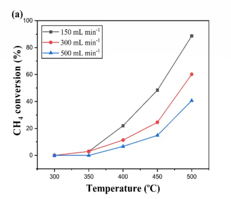
The methane conversion as a function of the reaction temperature (i.e., the oven temperature) 2
under different flow rates at an inlet oxygen to methane molar ratio (Φ) of 2 is shown in Fig. 4. 3
For a given temperature, a higher methane conversion was obtained at a lower flow rate, due to 4
a longer residence time (c.f. Eq. (4)). At the beginning when the operating temperature is 5
relatively low (300 - 350 oC), the methane conversion has no significant difference between
6
different flow rates (150 - 500 mL min-1). Under such circumstances, the reaction rate is slow
7
and (largely) controlled by kinetics (i.e., predominately determined by the reaction temperature 8
and catalyst mass). Thus, the methane conversion is at a very low level (< 3%) and the conversion 9
difference between each flow rate is not very discernible. As the temperature increased, the 10
methane conversion presented a significant increase and the light-off phenomenon occurred. 11
This indicates that the favorable coverage of the adsorbed methane and oxygen over the catalyst 12
surface facilitated by the temperature rise has been reached. Meanwhile, the significant increase 13
in the intrinsic kinetic rate and the catalytic activity during the light-off is likely attributed to the 14
rapid rise of the local temperature as well given the strongly exothermic reaction of methane 15
combustion. The light-off temperature corresponding to a 50% methane conversion (T50 value)
16
relevant to conditions in Fig. 4a is shown in Table 2. When the operating temperature continued 17
to increase (e.g., > 450 oC), the reaction tended to be (more) governed by mass transfer, because
18
the kinetic rate rapidly increased (according to the Arrhenius equation), but the gas-catalyst mass 19
transfer rate was hardly to catch up with (given much less comparable increase in the species 20
diffusivity in the gas mixture and coating). It is worth noting that the decrement in the methane 21
conversion rendered a slowdown when comparing 150 mL min-1 to 300 mL min-1 and 300 mL
22
min-1 to 500 mL min-1 throughout the temperature from ca. 400 to 500 oC. This is in line with
23
T50 value difference in Table 2.
24 25
19
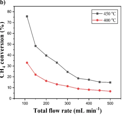
Fig. 4b further compares the methane conversion as a function of the flow rate at a given 1
temperature of 400 or 450 oC. The methane conversion presented an obvious decrease with the
2
increasing total flow rate, as already revealed in Fig. 4a. It is worth noting that the decrease in 3
the methane conversion at a sufficiently high flow rate tends to be insignificant. This could be 4
due to the improved external mass transfer at high flow rates which compensate, to some extent, 5
the conversion decrease (due to the shortened residence time). The conversion trends revealed 6
here are in general similar to those for the straight parallel channel microreactor tested in our 7
previous study [46]. These results confirm that the coating has been successfully applied onto 8
the current microreactor and functioned well in the CMC. 9
20 1
Fig. 4. Methane conversion as a function of (a) the temperature and (b) the total gas flow rate
2
over the washcoated 3.5 wt% Pt/γ-Al2O3 catalyst in Reactor #1 (straight parallel channel
3
microreactor). Conditions: T = 300 oC - 500 oC, Φ = 2, Qtot = 110 - 500 mL min-1.
4 5
Table 2
6
T50 value for the CMC experimental data presented in Fig. 4a.
7
Total flow rate (mL min-1) T50 a, b (oC) 150 451.8 300 487.6 500 516.0 Note: a T
50 indicates the temperature for reaching 50% methane conversion; Conditions are
8
shown in Fig. 4a. 9
21
b Estimated from the polynomial regression line used for fitting the measured conversion curve
1
as a function of the temperature for different flow rates. The polynomial is in the form of 𝑇𝑇50 =
2
𝐵𝐵0+ 𝐵𝐵1 𝑋𝑋𝐶𝐶𝐶𝐶4+ 𝐵𝐵2 𝑋𝑋𝐶𝐶𝐶𝐶2 4, where B0, B1 and B2 are the fitting constants. 3
4
3.1.2. Effect of catalyst loading and coating thickness
5
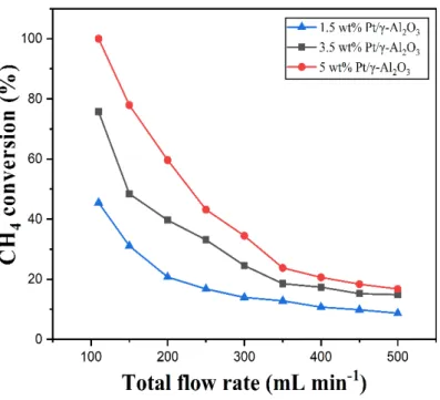
The reaction was further performed at various flow rates in Reactor #1 (straight parallel channel 6
microreactor) with different Pt loadings (1.5 wt%, 3.5 wt% and 5.0 wt% Pt/γ-Al2O3) by
7
maintaining almost a constant catalyst weight (𝑊𝑊𝑐𝑐𝑐𝑐𝑐𝑐= 0.25 ± 0.02 g). In more detail, during the
8
catalyst preparation only the concentration of Pt precursor solution was changed according to 9
the required Pt loading. The obtained results are presented in Fig. 5. At the same total gas flow 10
rate, a higher Pt loading (and with more Pt available in the catalyst) is accompanied by a higher 11
methane conversion. In other words, the overall reaction rate is significantly promoted by the 12
increased kinetic rate at higher Pt loadings. The methane conversion rendered an obvious drop 13
as increasing the total flow rate, due to the reduction of residence time. The extent of such 14
conversion decrease seems more pronounced especially at the highest catalyst loading studied 15
(5.0 wt% Pt/γ-Al2O3), indicating that the influence of the external mass transfer was more
16
pronounced therein given the highest kinetic rate involved. Furthermore, the external mass 17
transfer is related to many factors including the flow pattern, the diffusion rate, the channel 18
geometry, etc., by which the reactants have to be transported perpendicularly to the flow 19
direction from the center of microchannel to catalyst external surface [66]. A higher flow rate 20
(or larger Reynolds number) often leads to a higher external mass transfer rate [66]. However, a 21
higher flow rate also tends to incur a lower methane conversion due to the shorter residence time. 22
Thus, the decrement of methane conversion is generally dropped as shortened residence time as 23
presented in Fig. 5. 24
22 1
Fig. 5. Methane conversion as a function of the total gas flow rate over different Pt loadings in
2
Reactor #1 (straight parallel channel microreactor). Conditions: T = 450 oC, Φ = 2, Q
tot = 110 - 3 500 mL min-1, 𝑊𝑊 𝑐𝑐𝑐𝑐𝑐𝑐= 0.25 ± 0.02 g. 4 5
The internal mass transfer is mainly correlated to catalyst property including the catalyst 6
thickness, tortuosity, porosity and reactant diffusivity, etc. [66]. To further investigate the 7
influence of internal diffusion limitation (if present) on the microreactor performance, the 8
coating thickness of 3.5 wt% Pt/γ-Al2O3 catalyst was varied in the experiment by applying
9
different catalyst mass (Wcat) onto the reaction microchannel walls in Reactor #1. That is, the
10
higher the Wcat, the thicker the coating layer and subsequently the higher the specific catalyst
11
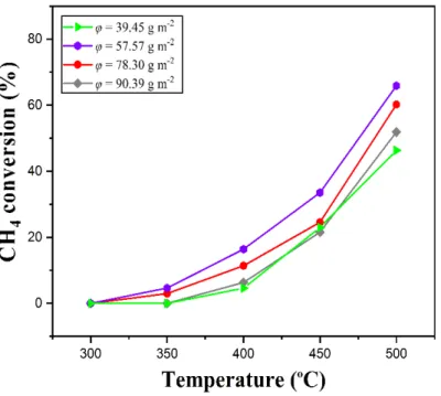
loading 𝜑𝜑 (Eq (5)). Microreactors with different values of 𝜑𝜑 varying from 39.45 to 90.39 g m-2
12
in Reactor #1 have been prepared, and the catalyst layer visually presented a uniform and well-13
dispersed coating throughout the parallelized reaction microchannels. Fig. 6 illustrates that the 14
methane conversion presents a maximum at about 𝜑𝜑 = 57.57 g m-2 for a given temperature (more
15
clearly seen at above 350 oC) and total flow rate. This phenomenon is probably due to a more or
23
less optimized match between the internal diffusion rate and the intrinsic kinetic rate at 𝜑𝜑 = 57.57 1
g m-2. For lower 𝜑𝜑 values (e.g., 39.45 g m-2), this might be explained by the fact that although
2
the thinner coating layer herein facilitated the internal diffusion due to the shorter path of 3
diffusion, and the accompanied insufficient amount of active sites for the reaction (given the Pt 4
weight proportionally decrease in the catalyst) has reduced the methane conversion. For higher 5
𝜑𝜑 values (e.g., 78.30 and 90.39 g m-2), the more significant internal diffusion resistance (longer
6
path of diffusion) is likely present due to the increased thickness of the catalyst layer, resulting 7
in a lower methane conversion (despite the higher intrinsic reaction rate due to Pt weight increase 8
in the catalyst based on Arrhenius equation). To be more specific, the higher Thiele modulus and 9
lower effectiveness factor could be obtained at the thicker catalyst coating, suggesting that the 10
effect of internal mass transfer at thicker coating is more pronounced on the methane conversion. 11
Thus the φ = 57.57 g m-2 is expected to be the optimized compromise between the (internal) mass
12
transfer and instinct kinetics. For a more quantitative prediction of the conversion trend as shown 13
in Fig. 6, a good knowledge on the reaction kinetics and reactant diffusion within the coating 14
layer (which depends primarily on the pore structure and morphology of the coating) need to be 15
further acquired. 16
24 1
Fig. 6. Methane conversion as a function of the reaction temperature under different specific
2
catalyst loading (𝜑𝜑) in Reactor #1 (straight parallel channel microreactor). Conditions: T = 300 3
- 500 oC, Φ = 2, Qtot = 300 mL min-1, 3.5 wt% Pt/γ-Al2O3 catalyst.
4 5
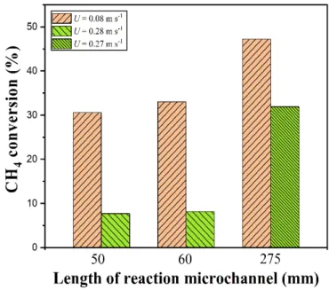
3.1.3. Effect of reaction microchannel length
6
To gain further insights into the influence of external mass transfer on the reaction rate, the 7
methane conversion in experiments with the straight parallel channel microreactors of different 8
reaction microchannel lengths (50-275 mm) is compared in Fig. 7, where the microchannel width 9
& height is the same. The specific catalyst loading is kept more or less identical (𝜑𝜑 = 82.5 ± 5 g 10
m-2). As displayed in Fig. 7, the methane conversion increased with increasing microchannel
11
length at 400 oC for a given mean velocity of the methane-air mixture (U; Eq. (6)). This is logical
12
given the increased residence time in the longer microchannel. A significant increase in the 13
microchannel length (from 60 to 275 mm) did not result in a conversion increase of similar 14
extent. This shows that the reaction is (at least) limited by the external mass transfer, given that 15
25
under internal diffusion limitation or kinetic control, the overall reaction rate should increase 1
linearly with the catalyst weight applied on the microchannel wall. 2
3
Fig. 7. Methane conversion as a function of the reaction microchannel length at different mixture
4
velocities (U). Conditions: T = 400 oC, Φ = 2, 3.5 wt% Pt/γ-Al2O3 catalyst, 𝜑𝜑 = 81.33, 78.30,
5
and 87.37 g m-2 for the microchannel lengths of 50, 60 and 275 mm, respectively, Data for 60
6
mm microchannel length is based on experiments with Reactor #1 (straight parallel channel 7
microreactor). Data for 50 mm and 275 microchannel lengths are from the respective 8
experiments with another microreactor of otherwise the same geometry and the microreactor 9
used in our previous study [46] (but with different numbers of microchannels of the same 10
width/height). 11
12
As already revealed in Fig. 4b, the methane conversion at a given temperature decreased with 13
the increasing flow rate in the microreactor (Reactor #1), which is insignificant at sufficiently 14
high flow rates (e.g., Qtot = 400 mL min-1; corresponding to a U of 0.28 m/s). The results of Fig.
15
7 further suggest that at such high Qtot or U values, the methane conversion can be still improved
16
by increasing the microchannel length (translated into a longer residence time). This also implies 17
26
that if the reaction is operated at a much higher Qtot (than 400 mL min-1) in Fig. 4b, a significant
1
drop in the methane conversion is expected (i.e., the conversion does not level off at such high 2
flow rates). 3
4
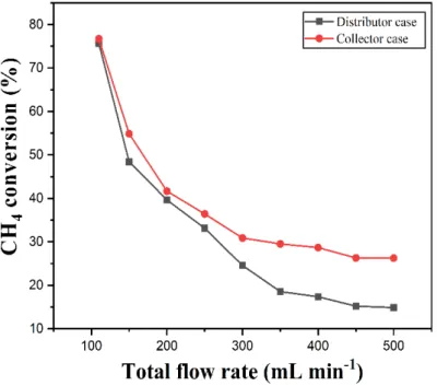
3.1.4. Effect of bifurcated tree-like structure as distributor or collector
5
The flow distribution behaviour within the reaction microchannel network may have a great 6
impact on the microreactor performance in the CMC. In the experiments performed above in 7
Reactor #1, the bifurcated tree-like structure was used as the inlet fluid distributor whereas a 8
simple rectangular collector at the microchannel outlet (Fig. 2). Regarding the multi-scale tree-9
like component, its relevant position with respect to the reaction microchannel will influence 10
flow distribution properties, as shown in the previous study [67]. In order to experimentally 11
verify the influence of such tree-like component on the catalytic performance, additional 12
experiments were performed with Reactor #1, by switching the microreactor outlet and inlet (i.e., 13
by feeding the gas mixture at the microreactor outlet). Thus, the tree-like structure functioned 14
here as the product collector and the rectangular chamber as the fluid distributor. 15
16
Fig. 8 presents an interesting observation: for Reactor #1, the tree-like structure used as the outlet 17
product collector exhibited a higher methane conversion than that used as the inlet gas 18
distributor. This indicates a somewhat significant difference in the pressure (drop) between the 19
distributor case and collector case [67]. When the tree-like structure was used as the gas collector, 20
the pressure drop in the collector side is higher than the case of using the simple rectangular 21
chamber as the collector, and the pressure drop in the distributor side is lower. This means that 22
in the former case, the local pressures at the inlet and outlet of the reaction microchannel are 23
higher than those in the latter case, which is beneficial for a more uniform fluid distribution and 24
thus a better methane conversion. In other words, the lower pressure drop on the distributor side 25
tends to improve the uniform delivery of fluid into each reaction microchannel, and the higher 26
27
pressure at the reaction microchannel outlet would make the flow therein less affected by the 1
flow behavior within the outlet collector structure. These are also in line with the literature 2
reporting that less vortex was produced and less energy was dissipated when using such tree-like 3
structure as the collector compared with the distributor case [67]. 4
5
Fig. 8 further shows that the conversion improvement in the former case is more pronounced at 6
higher total flow rates. This is possibly because the bifurcated tree-like distributor is shown to 7
be capable of guaranteeing a relatively uniform flow distribution among parallel channels/tubes 8
at small flow rates [68,69]. Nevertheless, the inevitable flow distribution non-uniformity at high 9
flow rates due to the increasing impact of inertial forces is an intrinsic character of such structure 10
[68]. Thus, the tree-like component used as the outlet collector is able to provide a more uniform 11
and stable flow distribution among parallel straight microchannels even under high flow rate 12
conditions. The residence time difference across different reaction microchannels is thereby 13
smaller, leading to a better usage of the catalysts and consequently higher methane conversion. 14
28
Fig. 8. Influence of the location of the tree-like bifurcated component (i.e., used as the inlet gas
1
distributor or outlet product collector) on the methane conversion in Reactor #1 (parallel straight 2
channel microreactor). Conditions: T = 450 oC, Φ = 2, Qtot = 110 - 500 mL min-1, 3.5 wt%
Pt/γ-3
Al2O3.
4 5
3.2. Comparison of the CMC performance in microreactors with different internal channel
6
configurations
7
In the following sub-sections, the CMC performance of Reactor #1 (parallel straight channel 8
microreactor) has been compared with other five plate-type microreactors with different internal 9
channel configurations as shown in Fig. 2, with regard to the effect of the operating temperature, 10
total gas flow rate and molar ratio of O2 to CH4 (Φ). In all reactors, the washcoated 3.5 wt%
Pt/γ-11
Al2O3 catalyst has the almost identical weight (0.25 ± 0.02 g; Table 1).
12 13
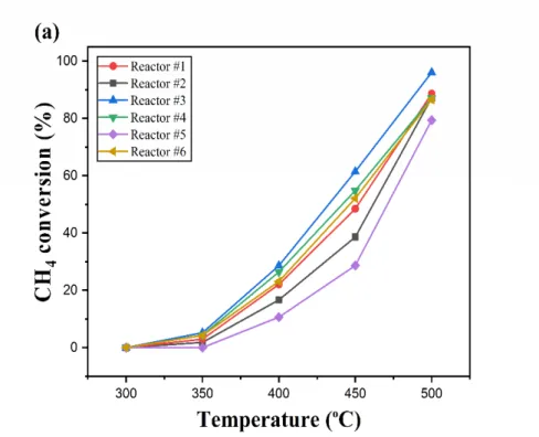
3.2.1. Effect of temperature on the performance of different microreactors
14
The methane conversion as a function of the reaction temperature in different microreactors is 15
shown in Fig. 9a-c for different total flow rates (150 - 500 mL min-1) and Φ = 2. The same trend
16
as presented in Fig. 4a was observed. At the lower temperature of 300 - 350 oC, the methane
17
conversion in all Reactors #1-6 is very low (< ca. 5%) and has no obvious difference at different 18
flow rates. This is because the reaction is mainly controlled by kinetics and mass transfer is not 19
the main factor determining the reaction rate. As the temperature increased, the methane 20
conversion presented a significant increase (especially at a lower flow rate), and the light-off 21
phenomenon occurred. An obvious difference in the methane conversion was found among the 22
different channel configurations of Reactors #1 - 6 at higher temperatures (> ca. 400 oC) when
23
the (external) mass transfer gradually became the limiting factor, especially at a relatively low 24
gas flow rate (e.g., 150 mL min-1; Fig. 9a). At a relatively high flow rate (e.g., 500 mL min-1;
29
Fig. 9c), the gap in the methane conversion between different reactors is narrowed, due to the 1
(largely) improved external mass transfer rate. 2
30 1
Fig. 9. Methane conversion as a function of the reaction temperature at the total flow rate of (a)
2
150 mL min-1, (b) 300 mL min-1 and (c) 500 mL min-1 in plate-type microreactors with different
3
channel configurations (Reactors #1 - 6). Conditions: T = 300 oC - 500 oC, Φ = 2, 3.5 wt%
Pt/γ-4
Al2O3 catalyst. Other reactor details and catalyst properties are shown in Table 1.
5 6
With regard to the different channel configurations in microreactors, the methane conversion 7
ranked with the following order: double serpentine channels (Reactor #3) > obstacled straight 8
31
channels (Reactor #4) > vascular network (Reactor #6) > straight parallel channels (Reactor #1) 1
> cavity (Reactor #2) > meshed circuit (Reactor #5). This trend is more pronounced at a lower 2
total flow rate (e.g., 150 mL min-1; Fig. 9a) and becomes insignificant at higher flow rate (e.g.,
3
500 mL min-1; Fig. 9c). The straight parallel channel microreactor (Reactor #1) presented a
4
higher methane conversion than the cavity microreactor (Reactor #2). The relatively lower 5
methane conversion in Reactor #2 might be due to the negative effect of the non-uniform velocity 6
profile of the gas since only 1 flat cavity was involved (Fig. 2), even though it has the longest 7
mean residence time (c.f. Table 1). In other words, the catalyst coating around the cavity 8
experienced different contact times with the reactant mixture, leading to an overall conversion 9
decrease. In contrast, the gas flow distribution should be (much) improved in Reactor #1, given 10
the flow was distributed into 16 parallel straight microchannels contributing to a more uniform 11
contact time between the reactants and catalyst. The obstacle reactor (Reactor #4) is actually an 12
improved version of Reactor #1, with a slightly higher coating surface area and longer mean 13
residence time (c.f. Table 1). Besides, the structure of successive obstacles with the split-and-14
recombine shape enabled to improve the gas mixing and further enhance the external mass 15
transfer compared to Reactor #1, especially at the mass transfer limited regime (at relatively 16
higher temperatures or low flow rates). It thus offered a slight increase in the methane conversion 17
under the same working conditions compared with Reactor #1. Among all the tested reactors, 18
the highest methane conversion has been achieved by using the double serpentine channel 19
microreactor (Reactor #3). This could be attributed primarily to a relatively higher coating 20
surface area (than all the others except Reactors #6) and relatively longer residence time (than 21
Reactors #1 and 4). In addition, the double serpentine structure could effectively promote the 22
gaseous mixing due to the formation of secondary flow on the channel cross-section [70], thus 23
improving their transfer to the coating external surface and contributing to a better conversion. 24
The vascular reactor (Reactor #6) has the highest coating surface area as well as a longer 25
residence time than the other reactors except Reactor #2 (Table 1). Despite these advantages, it 26
32
presented a methane conversion level in between those of Reactors #4 and 1 (Figs. 9a and b). 1
This is likely due to the non-uniform fluid distribution among the horizontal microchannel 2
sections and thus an insufficient utilization of the coated catalyst. Some microchannels could be 3
overloaded with gas mixture in the vascular network while others were underloaded, which 4
might be related to the vascular structure causing a less uniform distribution of gas mixture. An 5
improved design by carefully adjusting the resistance in the vertical diverging/converging 6
channels may help solve this problem, based on the study of Tondeur et al. [61]. The lowest 7
methane conversion was found in the meshed circuit microreactor (Reactor #5) under the same 8
tested conditions. It has been reported that the flow pattern in the meshed circuit was similar to 9
a continuous stirred tank reactor, and likely tended to be the divergent flow pattern even at low 10
Reynolds numbers [71]. This indicates that the gas has the chance to flow towards different 11
directions due to divergent flow appeared in the meshed circuit. This probably resulted in the 12
non-uniform flow distribution and/or somewhat broad residence time distribution, and thus a 13
lowest methane conversion. 14
15
Among the tested microreactors, the Reactor #3 (double serpentine microchannels) has the 16
highest pressure drop due to the longer channel length and the higher velocity. But its total 17
pressure drop was estimated to be smaller than 0.01 bar under the current experimental 18
conditions (500 mL min-1), lower than that present in fixed/packed bed reactors (e.g., mostly
19
above 0.1 bar [72]) especially when fine catalyst powders are used. 20
21
In summary, guidelines regarding the optimal channel configurations in plate-type microreactors 22
for the CMC should comprehensively consider the coating surface area, residence time 23
(distribution), fluid distribution uniformity, and the efficient use of catalyst in order to achieve a 24
desirable methane conversion. Further detailed investigation on the local flow and temperature 25
33
distribution characteristics by using simulation or optical visualization techniques would help 1
give a clearer view and better understanding in this aspect. 2
3
Fig. 10 depicts the methane conversion as a function of the operating temperature at Φ = 6 and 4
a total flow rate of 150 mL min-1 in Reactors #1 - 6. Similar conversion trends and the same
5
microreactor performance ranking were observed as compared to the case of Φ = 2 (Fig. 9a). A 6
lower methane conversion was obtained at Φ = 6 than Φ = 2. A comparison of T50 values at Φ =
7
2 and 6 for different channel configurations is also given in Table 3. It is found that the T50 value
8
at Φ = 2 is slightly lower than that at Φ = 6 for each channel configuration tested. In other words, 9
the methane conversion decreased a bit when Φ increased from 2 (stoichiometric ratio) to 6 10
(oxygen-rich). The competitive adsorption between methane and oxygen over the catalyst 11
surface could be one of the main reasons, given the methane adsorption energy is higher than 12
that of oxygen [73]. The adsorbed oxygen is likely to inhibit the weakly adsorbed methane in 13
these light-off experiments, leaving less chances for methane being further oxidized [74]. Thus, 14
the favorable fractional coverage of adsorbed reactants over the active sites is essential for 15
achieving the desired methane conversion. However, caution must be taken when interpreting 16
the trend because the difference in the T50 value under Φ = 2 and Φ = 6 is only several degree
17
Celsius (c.f. Table 3). An opposite trend may be observed when the operating procedures change 18
as will be further discussed in the following sub-section. 19
34 1
Fig. 10. Methane conversion as a function of the temperature in plate-type microreactors with
2
different channel configurations (Reactors #1 - 6). Conditions: T = 300 - 500 oC, Φ = 6, Q
tot =
3
150 mL min-1, 3.5 wt% Pt/γ-Al2O3 catalyst. Other reactor parameters and catalyst properties are
4 shown in Table 1. 5 6 Table 3 7
T50 value for the CMC experimental data presented in Figs. 9a and 10.
8 Reactor T50(oC) a, b Φ = 2 Φ = 6 #1 460.0 462.8 #2 451.8 456.4 #3 437.5 443.5 #4 446.0 448.4 #5 470.6 472.2
35
#6 449.8 452.2
a T50 indicates the temperature for reaching 50% methane conversion; Conditions are shown in
1
Figs. 9a and 10. 2
b Estimated from the polynomial regression line (cf. other details in Table 2).
3 4
The results of Fig. 9 were obtained in Reactors #1 - 6 with almost identical catalyst mass. Due 5
to the surface area difference, the specific catalyst loading (𝜑𝜑) differs to some extent per reactor 6
(Table 1). This implies a coating thickness difference, which could lead to a different influence 7
of internal diffusion on the overall reaction rate in each microreactor. To further shed light on 8
this, some additional experiments were conducted in Reactors #1, 3 and 6, but now with almost 9
the same specific catalyst loading (𝜑𝜑 = 90.5 ± 0.5 g m-2) by adjusting the coated catalyst mass
10
accordingly. As shown in Fig. 11, the same conversion trend as a function of the temperature (at 11
a total flow rate of 300 mL min-1 and Φ = 2) was observed in Reactors #1, #3, #6 as presented in
12
Fig. 9b. Also, the methane conversion decrease follows the same order of Reactor #3 > Reactor 13
#6 > Reactor #1, especially at relative higher temperatures (e.g., > 400 oC). Since in these reactors
14
the coating thickness can be considered identical, the difference of methane conversion between 15
each reactor is attributed to different channel geometries resulting in the different coating surface 16
area, fluid mixing behaviour and residence time property therein. 17
36 1
Fig. 11. Methane conversion as a function of the temperature in plate-type microreactors with
2
different channel configurations (Reactor #1, 3 and 6). Conditions: T = 300 - 500 oC, Φ = 2, Q
tot
3
= 300 mL min-1, 3.5 wt% Pt/γ-Al
2O3 catalyst, 𝜑𝜑 = 90.5 ± 0.5 g m-2 (realized by adjusting the
4
coated catalyst mass). Other reactor parameters and catalyst properties are shown in Table 1. 5
6
3.2.2. Effect of molar ratio of O2 to CH4
7
To investigate the effect of the inlet molar ratio of O2 to CH4 (Φ), the CMC experiments were
8
further conducted in Reactors #1 - 6 at 450 oC and 150 mL min-1. The results of different tested
9
reactors are shown in Fig. 12, which reveal the same trend in terms of the microreactor 10
performance rank as that shown in Fig. 9a. As Φ was increased from 0.5 up to 1.5, the methane 11
conversion was improved gradually in each microreactor, which is due to the (severely) 12
insufficient supply of oxygen limiting the adsorbed methane to be further converted. A relatively 13
smaller difference in methane conversion presented in this region between different 14
microreactors compared to that of Φ ≥ 1.5, and the (external) mass transfer shown a more 15
pronounced effect. The highest methane conversion was found at ca. Φ = 1.5 (instead of 2 as the 16
37
stoichiometric ratio for the methane combustion) for each tested channel configuration. Oh et al. 1
[75] also reported that operating at methane-rich conditions provided the best catalyst 2
performance and increasing the oxygen concentration resulted in a sharp decrease in the catalyst 3
activity.It could be thus due to firstly at Φ = 1.5, there is an increased oxygen supply together
4
with the consumption of methane in not only the combustion reaction, but also side reactions 5
(such as methane partial oxidation and steam reforming) that require less amount of oxygen [76]. 6
Moreover, a higher light-off temperature is required for the above-mentioned side reactions than 7
for the methane combustion [77]. Such side reactions are more favoured to occur at higher 8
temperature levels (e.g., at 450 oC relevant to Fig. 12). The existence of a variety of complex
9
reactions under oxygen-lean conditions can be confirmed by the selectivities of CO2, CO and H2
10
as displayed in Fig. 13. For Φ ≥ 2, only CO2 could be found as product (𝑆𝑆𝐶𝐶𝐶𝐶2= 100 %) while no
11
CO or H2 was detected in the product gas. For Φ < 2, more amounts of CO and H2 were produced,
12
i.e., the selectivity of CO is ca. 2% - 4% and H2 ca. 4% - 16% while the rest product is CO2.
13
Moreover, it seems that a balance between the adsorbed oxygen and methane has been achieved 14
on the catalyst surface at ca. Φ = 1.5 for the best methane conversion, which largely explains the 15
significant conversion drop at Φ = 2 or above. A way to further increase the methane conversion 16
(e.g., to above 90%) at this stoichiometric ratio is by raising the reaction temperature (e.g., see 17
Fig. 9a). 18
19
In our experiments, the proportion of CO2 in the product at ca. Φ = 1.5 is too high to achieve a
20
desirable synthesis gas ratio of H2/CO. It might be due to the reactant ratio and the catalyst used
21
in this study that result in the overoxidation of products. The effects of the reactant ratio, 22
pressure, temperature and mechanisms on the product selectivity have been evaluated in many 23
earlier studies [78-80], but additional works remain to be performed in this respect for the 24
purpose of syngas production by methane partial catalytic oxidation. 25
38
With Φ increasing from 2 to 6, the hysteresis effect plays an important role in determining the 1
reaction conversion. The concentration hysteresis phenomenon has been demonstrated via 2
switching the molar ratio of O2 to CH4 [81,82]. That is, a (relatively) high conversion state has
3
been previously obtained at Φ = 0.5 - 1.5 could be maintained to some extent when further 4
increasing the Φ value afterwards. Under such circumstances, the catalyst surface was primarily 5
dominated by the adsorbed oxygen over the catalyst surface, and the oxygen concentration on 6
the catalyst could be considered as constant in the present molar ratio experiment due to high 7
conversion state. Given the less methane present in the feed and competing for a constant number 8
of active sites, relatively more methane had the possibility to be adsorbed and converted, leading 9
to a slight conversion increase at Φ > 2. 10
11
To further elucidate the observed conversion trend especially at Φ > 2, Table 4 compares the 12
methane conversion in the light-off experiment (Figs. 9a and 10) and that in the molar ratio 13
experiment here (Fig. 12) under the same working conditions. The results shown that the 14
methane conversion displayed a slightly decrease as increasing O2/CH4 molar ratio, and on the
15
contrary, the methane conversion turned out to be consistently higher in the molar ratio 16
experiment. In the light-off experiment, as the experiment has been performed by increasing the 17
temperature from 300 oC to 500 oC at a constant O2/CH4 molar ratio, the concentration hysteresis
18
phenomenon is thus absent when switching from the low temperature (low conversion state) to 19
high temperature (high conversion state). The favorable coverage between the adsorbed methane 20
and oxygen has been achieve at Φ = 2, and the lower methane conversion at oxygen-rich 21
environment (Φ = 6) could be reasonably explained by the competitive adsorption. The adsorbed 22
oxygen could prevent the further oxidation of adsorbed methane over the catalyst surface due to 23
the lower oxygen adsorption energy [73]. However, in the molar ratio experiment, a higher 24
methane conversion obtained at Φ = 6 can be explained by the concentration hysteresis 25
phenomenon present (procedurally/prehistorically related), as has been explained above. 26