Poly-SiGe-based MEMS Xylophone Bar Magnetometer
V. Rochus, R. Jansen, H. A. C. Tilmans, X. Rottenberg
Interuniversitair Micro-Electronica Centrum Imec, Leuven, Belgium
C. Chen
Interuniversitair Micro-Electronica Centrum Imec, Taipei, Taiwan
S. Ranvier, H. Lamy
Belgian Institute for Space AeronomyBIRA, Brussels, Belgium
P. Rochus
Centre Spatial de LiègeCSL, Liège, Belgium
Abstract—This paper presents the design, fabrication and
preliminary characterization of highly sensitive MEMS-based Xylophone Bar Magnetometers (XBMs) realized in imec’s poly-SiGe MEMS technology. Key for our Lorentz force driven capacitively sensed resonant sensor are the combination of reasonably high Q-factor and conductivity of imec’s poly-SiGe, our optimized multiphysics sensor design targeting the maximization of the Q-factor in a wide temperature range as well as our proprietary monolithic above-CMOS integration and packaging schemes. Prototypes 3-axis devices were fabricated and characterized. We present optical vibrometer and electrical S-parameter measurements of XBMs performed in vacuum with a reference magnet at increasing sensor separation. The optical oscillation amplitude is well correlated with the magnetic field amplitude. The electrical 2-port measurements, 1st port as
Lorentz force actuator and 2nd port as capacitive sensor, also
reproduces the designed magnetic field dependence. This opens the way towards the on-chip integration of small footprint extremely sensitive magnetometers.
I. INTRODUCTION
MEMS-based inertial measurement units (IMUs) have gained the status of mainstream commodities for consumer electronics in the past years. From the simple 1-axis accelerometer, IMUs have evolved to provide 3 degrees-of-freedom (DOFs) accelerometer sensing and eventually to 6DOFs modules, including angular rate sensors. In particular, the synergy of multi-DOF inertial sensors turned out to be key in improving the navigation capabilities of inertial modules The trend towards development of multi-DOF modules goes on [1]. On-chip magnetometers are seen as key components to further improve the performance of IMUs and navigation modules.
This paper presents the design, fabrication and preliminary characterization of sensitive MEMS-based Xylophone Bar Magnetometers (XBMs)[2][3] realized in imec’s poly-SiGe MEMS technology[4]. Key for our Lorentz force driven capacitively sensed resonant sensor are the combination of
reasonably high Q-factor and conductivity of imec’s poly-SiGe, our optimized multiphysics sensor design targeting the maximization of the Q-factor in a wide temperature range as well as our proprietary monolithic above-CMOS integration and packaging schemes. Prototypes 3-axis devices were fabricated and characterized. We present optical vibrometer and electrical S-parameter measurements of XBMs performed in vacuum with a reference magnet at increasing sensor separation. The optical oscillation amplitude is well correlated with the magnetic field amplitude. The electrical 2-port measurements, 1st port as Lorentz force actuator and 2nd port
as capacitive sensor, also reproduces the designed magnetic field dependence. This opens the way towards the on-chip integration of small footprint extremely sensitive magnetometers.
II. XYLOPHONE BAR MAGNETOMETERS A. Principle of operation
The studied device is based on a classical resonating xylophone bar. Xylophones are mechanical resonant beams supported in the nodes of their first fundamental transverse mode of vibration as shown in Figure 1. Placed at the “non-deflecting” parts of the oscillating structure , the supports have the lowest effect on the dynamics of the structure. A sinusoidal current is supplied to the baeam and when an external magnetic field (Bext) is present, the resulting Lorentz
force causes the beam to vibrate with an amplitude directly proportional to the y-component of the ambient magnetic field. When the driving frequency is equal to the fundamental resonant frequency of the beam the amplitude of vibration will be maximal as explained below.
The fundamental transverse resonant frequency f0 of a free-free beam is given by (1) where E is the Young’s modulus, ρ is the mass density of the beam material, and L/b/t are the length/width/thickness of the beam. Ia is the area moment of inertia (i.e., bt³/12, for a beam with a rectangular cross-section), m the mass per unit length (i.e. ρtb). When
b>5t, E has to be replaced by the plate modulus E/(1–ν²) in (1)
where ν is the Poisson’s ratio of the beam material.
Figure 1 Schematic description of a xylophone bar magnetometer
When a current I is driven through the xylophone bar in the presence of an external magnetic field Bext, a resulting Lorentz force given by (2), where and Ix is the current in the x-direction, is exerted on the bar. In case of AC-current excitation, the displacement amplitude at the center of the bar is a function of the drive frequency given by (3) in the vicinity of the resonance frequency f0. When the frequency of the current is set at the f0, the deflection of the bar is strongly enhanced and given by (4) where Q is the mechanical quality factor which is determined by different parameters depending on bar material, manufacturing process, but also includes various types of damping such as viscous (air), acoustic, thermoelastic, surfacial [3]. ρ π E L t mL EI f a 2 4 0= 222.4 =1.029 (1) z s y x ext s B I B Le L I FG= G ∧ G = G (2)
(
) ( )
(
(
)
)
(
)
2 0 2 2 0 0,0 1 0 ,x w f f f f Qf f w = = − + (3)( )
Q EI L B I e Q EI L B I f w a y x a s y x 4 4 0 384 1.21 3 5 0 , = = − (4)Equation (4) shows that the amplitude of the deflection of the bar is linearly proportional to the magnetic field component By parallel to the surface of the XBM and normal to the direction of the drive current. XBMs are therefore, unlike many other magnetometers, intrinsically linear. They also feature wide dynamical ranges, i.e. resolvable Bext from nT to T, enabled by adjusting the drive current amplitude. However, the maximum intensity of the current that can flow
through the bar depends on the importance of the Joule effect and of the thermomechanical coupling. Indeed, a too large temperature change in the bar could result in significant modifications of its mechanical properties possibly leading to erroneous read-out.
B. Design and modelling of SiGe-based devices
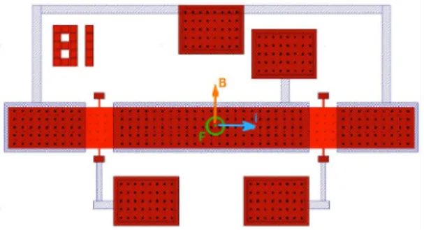
The XBMs presented here are made with the poly-SiGe MEMS process developed by IMEC [5][4]. In-plane magnetometers were designed to measure the magnetic field in the plane as depicted in Figure 2 and Figure 3(a). The drive current is fed through the support onto the XBM that is made to oscillate out-of-plane proportionally to the in-plane component of the field Bext. Three electrodes are defined under the XBM, i.e. a large one between the supports and two small ones under the outer edges of the device, to provide capacitive sensing capabilities. Combining two of these devices rotated by π/2 allows measuring the two in-plane components of Bext. The 3rd component of Bext is obtained using the device of Figure 3 (b), that is built to oscillate in-plane.
Figure 2 Layout of in-Plane Poly-SiGe magnetometers.
(a)
(b)
Figure 3 Top view microphotograph of (a) an in-plane XBM from the family introduced in Figure 2and (b) an out-of-plane XBM.
The typical dimensions L/b/t of the designed in-plane XBMs are 500/50/4μm. The torsional support width is fixed by the technology to the minimal dimension of 2μm, and its length ranges from 2µm to 50µm. The material properties of the poly-SiGe are listed in TABLE I where ρe, α and k are
respectively the electrical resistivity, thermal expansion coefficient and thermal conductivity. Figure 3 shows a picture of one prototype fabricated in poly-SiGe.
TABLE I POLY-SIGE MATERIAL PROPERTIES.
E [GPa] ν ρ [kg/m³] ρe [Ωm] α [1/Κ] κ [W/mK]
117 0.22 4800 7e-6 4.7e-6 3
1) Electro-thermal simulations:
For the typical dimensions of the XBM, a voltage V0 is
applied at the extremity of the support. An electrokinetic simulation is performed to evaluate the current density passing through the device and a thermal simulation provides the increase of temperature due to the Joule effect. In Figure 4 the increase of temperature is plotted versus the applied current. The graph displays the expected parabolic relationship (ΔT proportional to power I2R): For a current of 1mA, the increase
of temperature is about 5°C. The temperature variation reaches 20°C if the current is 2mA. For a variation of 100°C, the current is 4.5mA. To be conservative a current of 1mA will be driven through the devices.
Figure 4 Temperature increase due to Joule effect obtained by the electro-thermal simulation when the current is increased for the SiGe-XBM; inset
showing the current distribution on a quarter of the device.
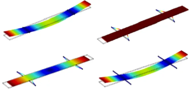
Figure 5 On top: first eigenmode for Ls=4μm (on the left) which is the free-free beam mode and for Ls=50μm (on the right) called the translation mode. On the bottom, the initial deformation due to the residual stress (x200)
for Ls =50μm on the left and the associated mode shape on the right. 2) Effect of Residual Stress on the Mode Shapes:
The eigenfrequencies and eigenmodes are computed for different support lengths in order to observe the effect of the support. In figure 7 the frequency is plotted versus the length of the support Ls for a L/b/t=500/50/4μm magnetometer. When
Ls increases, the frequency converges to the analytical solution for a free-free beam: 81kHz. At the same time, another mode, i.e. translation mode, appears in the same range of frequency, perturbing the excitation of the wanted mode. The two first pictures on the top of the figure 6 show the first mode for Ls = 4μm which is the actuation mode and the first mode for
Ls=50μm which is called the translation mode. Considering that the SiGe Layer has a residual stress of 60MPa, the mode and the frequency are slightly modified as observed in figure 7 and the frequency of translation mode is now larger than the actuation mode frequency for long support lengths. On figure 6, we can observe on the bottom left the initial deformation due to the residual stress (increased by a factor of 200) and on the bottom right the associated mode shape. The residual stress has a quite low and positive influence on the mode shape.
Figure 6 The two first eigenfrequencies computed using COMSOL for different lengths of supports with and without residual stress. 3) Harmonic simulation:
Harmonic simulations require loss mechanisms to be defined in order to produce representative results. In particular, the quality factor of each resonance has to be estimated. The damping for the XBM comes from different origins and the final damping is the sum of various effects such as the thermoelastic damping, the support damping, the air damping and the material damping. The latter damping highly depends on the material quality as well as its processing quality that cannot be estimated analytically nor by numerical simulations. From various experimental data we know that SiGe depicts excellent Q-factor (material Q of around 30,000). However, for the harmonic simulation presented in Figure 7 we used a rather conservative value of 1000 for the overall Q.
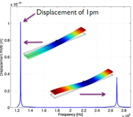
Considering a current of 1mA applied to the SiGe-XBM and Bext=1μT we estimate using (4) the maximum displacement to reach 2.4pm amplitude. In the same condition, we simulate the harmonic response taking into account the actual shape of the device in the presence of residual stress. Figure 7 presents the dynamic response of the SiGe-XBM for Ls=4μm. The two first modes are obtained around 125kHz and 270kHz with a clearly larger rms displacement amplitude of the order of 1pm for the first one.
Figure 7 Simulated harmonic response (vibration amplitude) of a SiGe-XBM with Q=1000, for an external field of 1μT and a current of 1mA with
inset showing the eigenmodes of ¼ of the total XBM.
III. CHARACTERIZATION
For their optical characterization, we drove various XBMs in vacuum using a Karl-Süss environmental chamber and tracked their maximum displacement amplitude, w(f, 0), using a Polytec laser Doppler vibrometer (LDV). A reference magnet placed on a manipulator was used to vary the effective
Bext. Figure 8(a) shows the result of such a measurement. With decreasing magnet separation, w(f, 0) and in particular w(f0, 0) increase. Note that at large magnet separation, a remnant oscillation is noticeable. This is attributed to the background earth Bext, of the order of 60µT. Indeed, with this value of Bext, 1mA excitation current and the measured Q-value of 5000, the estimated w(f0, 0) reaches 0.7nm using (4), well in line with the measured 0.6nm. This oscillation introduced by the earth magnetism is more visible in Figure 8(b), where XBMs differing only by their support length, Ls, are compared in
presence and absence of reference magnet. With increasing Ls, the compliance of the support increases and the oscillations of the devices increase at constant excitation.
Figure 8 Polytec LDV measurement of w(f, 0) in vacum for typical XBMs under 1mA AC drive; (a) with Ls=2µm ad decreasing magnet separation; (b)
with increasing Ls in absence/presence of reference magnet (dashed/full line).
Finally, we report on the electrical 2-port S-parameter measurement of XBMs using an Agilent vector network analyzer (VNA). The first port of the measurement setup is used as an AC drive excitation while the second port, implementing DC-biasing, is connected to the capacitive sensing electrodes of the device. Figure 9 shows the result of such a measurement in vacuum at 0dBm input power, under 30V DC bias for a typical device at decreasing magnet separation. The transmission amplitude is well correlated with the input field through the magnet separation. These S21
-parameters were obtained for the standard SiGe-MEMS
technology from imec [4], implementing 3µm vertical capacitive sensing gaps. The implementation of a sub-micron thin gap module available in imec’s SiGe-MEMS platform [6] would result in a more than 100 times improvement of the demonstrated sensitivity. 9 9.05 9.1 9.15 9.2 9.25 9.3 x 10⁴ -115 -110 -105 -100 -95 -90 -85 Frequency [Hz] S2 1 [ d b m ] dist = 300µm dist = 2100µm dist = 2900µm dist = 5300µm
Figure 9 Measured magnitude of the transmission parameter S21 of an
XBM placed in vacuum for various magnet separation.
IV. CONCLUSIONS
In this paper, we presented the design, fabrication and preliminary characterization of MEMS-based XBMs realized in imec’s poly-SiGe MEMS technology. Optical LDV and electrical S-parameter measurements performed in vacuum with a reference magnet at increasing sensor separation demonstrated the proper function of the devices. The optical oscillation amplitude is well correlated with the magnetic field amplitude. The electrical 2-port measurements, 1st port as Lorentz force actuator and 2nd port as capacitive sensor, also
reproduces the designed magnetic field dependence. This opens the way towards the on-chip integration of small footprint extremely sensitive magnetometers.
REFERENCES
[1] C. L. Roozeboom, J. Y. Sim, D. Wickeraad, B. Dura, W. S. Smith, M. A. Hopcroft, P.G. Hartwell, R.S. Williams, B.L. Pruitt, “MEMS multi-functional integrated sensors for the environment”, Proc. of MEMS’12, pp.144-7, Jan. 2012.
[2] D. Oursler, D. Wickenden, L. Zanetti, T. Kistenmacher and R. Givens, “Development of the johns hopkins xylophone bar magnetometer”, tech. rep., DTIC Document, 1999.P. Helin, P. Czarnecki, A. Verbist, G. Bryce, X. Rottenberg and S. Severi, “Poly-SiGe-based CMUT array with high acoustical pressure”, Proc. of MEMS’12, pp.305-8, Jan. 2012.
[3] H. Lamy, I. Niyonzima, P. Rochus and V. Rochus, “A xylophone bar magnetometer for micro/pico satellites”, Acta Astronautica, 67 (2010), pp. 793–809.
[4] http://www.europractice-ic.com/MEMS_imec_SiGeMEMS.php [5] L. Wen, K. Wouters, L. Haspeslagh, A. Witvrouw, R. Puers, “An
in-plane SiGe differential capacitive accelerometer for above-IC integration”, in J. of Micromech. and Microeng., vol. 21, no. 7, 2011 [6] P. Helin, P. Czarnecki, A. Verbist, G. Bryce, X. Rottenberg and S.
Severi, “Poly-SiGe-based CMUT array with high acoustical pressure”, Proc. of MEMS’12, pp.305-308, January 2012.