HAL Id: hal-01913382
https://hal.archives-ouvertes.fr/hal-01913382
Submitted on 6 Nov 2018HAL is a multi-disciplinary open access archive for the deposit and dissemination of sci-entific research documents, whether they are pub-lished or not. The documents may come from teaching and research institutions in France or abroad, or from public or private research centers.
L’archive ouverte pluridisciplinaire HAL, est destinée au dépôt et à la diffusion de documents scientifiques de niveau recherche, publiés ou non, émanant des établissements d’enseignement et de recherche français ou étrangers, des laboratoires publics ou privés.
Effect of Axial Preload on Double-Lap Bolted Joints:
Numerical Study
Taha Benhaddou, Pierre Stéphan, Alain Daidié, Feras Alkatan, Clément
Chirol, Jean-Baptiste Tuery
To cite this version:
Taha Benhaddou, Pierre Stéphan, Alain Daidié, Feras Alkatan, Clément Chirol, et al.. Effect of Axial Preload on Double-Lap Bolted Joints: Numerical Study. ASME. ASME 2012 11th Biennial Conference on Engineering Systems Design and Analysis Volume 3: Advanced Composite Materials and Processing; Robotics; Information Management, pp.769-776, 2012, �10.1115/ESDA2012-82728�. �hal-01913382�
Effect of axial preload on aerospace fastened joints
durability
Taha BENHADDOU *1, Pierre STEPHAN 2, Alain DAIDIE 3, Feras ALKATAN 4, Clement CHIROL 5 Jean-Baptiste TUERY 6
(1)(2)(3)(4) : Institut Clément Ader - Insa de Toulouse, 135 avenue de Rangueil - 31077 Toulouse Cedex 4 (5)(6) : Airbus Operations SAS, 316 Route de Bayonne. 31060. Toulouse Cedex 9
* Correspondent author. Email: [email protected]
Abstract:
The main aim of the present work is to study the effect of axial preload on the durability of aerospace fastened joints. For that, experimental and numerical approaches have been adopted to demonstrate the beneficial effect of axial preload on the fatigue life of representative aerospace fastened joints. In the experimental approach, an innovative tightening technique, based on iterative tightening, has been used to reduce the generated scatter induced on preload when using conventional torque tightening technique. The main benefit besides the use of this alternative tightening technique is to allow accurate preload introduction without geometry or stiffness modification, thus allowing to determine precisely the preload effect. The results shows the effect of preload on static resistance, fatigue life and failure mode of fastened joints. In the numerical approach, a 3D finite element model has been developed and the analysis of its behavior confirms and explains experimental observations. Analysis of longitudinal stresses through critical paths shows that the effect of high preload is beneficial due to the reduction of hydrostatic pressure and shear stress amplitude, leading to higher fatigue lives. Application of SWT and Crossland multiaxial fatigue criteria allows to correlate to experimental observations.
Keywords: axial preload; process for durability; fastened joints; fatigue life enhancement; finite elements analysis.
1- Introduction
Joining technologies are essential to the design and production of most mechanical structures. In particular, and when the mechanical structures are large as for aero-structures, it is often necessary, for technical and / or economic reasons, to conceive them in the form of a set of smaller dimensions parts that can be joined together. Fastened joining technique is widely used because of its ease of use, its efficiency and its relative low cost. However, fastening requires drilling holes in joined plates, leading to stress concentration areas and promoting fatigue cracks initiation from hole edges.
Several design and manufacturing processes can be used to improve the fatigue resistance of double lap bolted joints:
1- Interference radial mounting, consisting of a negative fit between the bolt shank and the bore of the plates holes (Duprat et al. [12]).
2- Cold expansion, consisting of radial expansion of the plate’s holes by pulling a tapered mandrel, pre-fitted with a lubricated split sleeve, through the plate’s holes, as shown by Yongshou et al. [30] for rectangular plates and Huang et al. [15] for lugs.
3- Axial preload, commonly introduced through torque application (Minguez and Vogwell [19]).
For these three joining processes, the stresses distribution around the plate’s hole is modified with the introduction of axial and/or radial compressive residual stresses, making it possible to improve fatigue strength.
Several works deal with improving the fatigue strength of assemblies as a function of the interference, expansion and / or preload applied to both single-lap and double-lap bolted joints. Duprat et al. [12] showed a significant improvement in fatigue life in the case of interference mounting with an optimal fatigue life obtained around an interference value of 1.5%. The shown improvement is related to the residual tensile stresses field near the hole leading to a significant reduction of the cyclic stresses amplitude.
A comparative study conducted by Lam [16] on the fatigue behavior of cracked holes using either interference mounting or cold expansion processes showed that for a low loading ratio and one low starting crack, interference is not as effective as cold expansion to extend the lifetime. On the other hand, the interference is less sensitive to the loading ratio and to the initial crack size.
The effect of torque tightening on static and fatigue resistance of single and double lap bolted joints has been addressed through many experimental research studies. Several authors had shown the positive effect of high torque on such joints. Shankar and Dhamari [24] showed this beneficial effect on double lap joints and Chakherlou et al. [5] on simple preloaded plates. The reported increase can be very significant, and reaches an asymptote after which the fatigue life stays constant or can even decrease. Indeed, Wagle and Kato [29] have shown that fatigue life of double lap shear joints decreases if the applied torque is too high, due to fretting fatigue. Therefore, determining optimal preload value and its allowable scatter is of major interest to permit maximal fatigue resistance of the joint. In addition, the allowable scatter determination should allow to select the most appropriate tightening method, in relation to the industrial constraints.
The improvement of fatigue resistance, due to application of high torque, is leading to the fatigue crack initiation position modification: for low torque values, the crack initiates from hole edges. However, when high torque is applied, the crack initiates in the gross section, outside of compressed area (Schijve [23]). A comparable modification has been reported for joints with a high degree of interference or expansion percentages (Hahn et al. [14]).
Preload control is of great importance to guarantee the mechanical strength of single and multi-material fastened joints, whatever the type of external solicitation. In particular, under cyclic transverse loading, an insufficient level of preload does not allow to exploit the load transfer capacity of the joint interfaces. A very high level of preload is not desirable either, since it generates fretting-fatigue phenomena or excessive fastener underhead over-pressure which can result a detrimental effect on the fatigue life of joints and structures. Therefore, preload controlled tightening produces and maintains a balance between the modes of load transfer mechanisms, making it possible to fully exploit their potential and to obtain an optimum clamping of the joint (Benhaddou et al. [2]). The control of preload-linked parameters such as the nature of the joint interface, the fasteners stiffness’s and the radial fitting nature could lead to perform further optimization of fastened joints. In the case of linear or non-linear axial loadings, a controlled preload level improves the service life of the joint thanks to an external load filtering effect which reduces the severity of external loads, especially in stress concentration areas (Bickford [3]).
In the industrial side, different methods exist to control the preload of a threaded fastener. The most commonly used is torque tightening. The nominal torque necessary to tighten the bolt to a given preload is calculated using a relationship between torque and the resulting bolt pretension. However, a variation of 30% in installed preload is common with torque tightening methods (Bickford [3]).This torque-preload relationship is significantly affected by the used materials, the geometry of the assembly, the surfaces finishing, the lubrication and the surface treatment, the heat treatment of the fastener, the threads type, the tightening speed ... In particular, friction coefficients variability within the assembly plays a predominant role in the definition of the relationship between torque and preload and justifies the scatter commonly generated on preload when using torque tightening. Consequently, using alternative tightening techniques to reduce the scatter, will allow reducing the number of fasteners or their diameter whilst using the maximal capacity of the bolt material. Using more cost-effective bolt material with a lower tensile strength can also be considered.
In addition, friction coefficient between joined plates plays also a significant role in fatigue resistance of bolted joints.Interfay sealant application between joined plates have a negative effect on their fatigue resistance due to the decrease of global friction coefficient (Boni and Lanciotti [4]).
The combined influence of interference mounting and torque tightening (Abazadeh and al. [1]) or cold expansion and torque tightening (Chakherlou et al. [6], extended by Taghizadeh et al. [28]) has been studied and showed an additional enhancement of fatigue resistance when the two processes are used. In the case of torque effect, numerical simulations that were performed shows that stress distribution around the plate’s holes is greatly affected by the torque or preload value. In keeping with the reported literature, understanding preload effect is the main aim of the present study. Indeed, the dissociation of preload and torque is the focal point of the present research. Thus, preload effect, obtained by accurate tightening mean instead of torque tightening technique, can be rigorously assessed.
2- Experimental approach
2.1- IntroductionIn order to demonstrate the beneficial effect of preload on double lap fastened joints, an extensive testing campaign was conducted. For the considered double lap joint, two distinct load transfer mechanisms are interacting for this kind of joint. The first one is the friction mode, allowing to transfer load through the adherence between plates, due to applied preload. The second one is the bearing load, for which load is transferred through the contact between the
2.2- Tightening operation
In order to achieve application of a precise preload, a dedicated tightening mean based on iterative tightening technique was used. As stated in the introduction, tightening torque induces a fairly dispersive preload within the joint (which can be as much as +/- 30% uncertainty over the final preload value). The applied technique within the experimental campaign is based on the iterative technique and reduces this uncertainty to a measured value of + 10% on the final value, allowing to apply precise preload whilst avoiding modifying the joint geometry and stiffness through the use of strain or tension indicating washers.
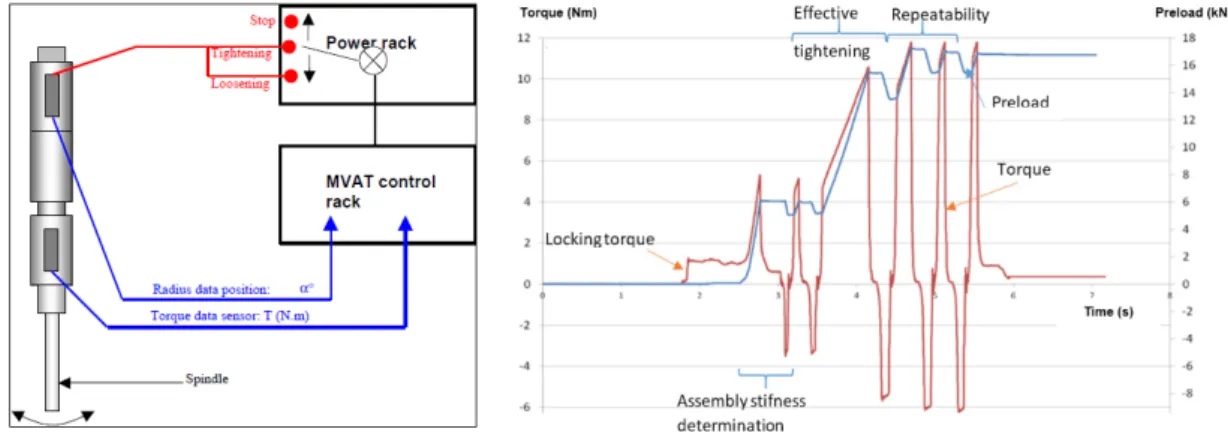
The principle of the iterative tightening is to apply a succession of tightening and untightening operations in order to better evaluate the torque generated by friction between the surfaces in contact (nut / plate, screw / plate and screw / nut), thus allowing to achieve a less scattered preload. Figure 1 shows an overview of the tightening mean and an example of the tightening sequence, representing the evolution of preload and torque in relation to time and describing the different steps of iterative tightening: overcoming locking torque then determining joint stiffness through geometric and friction parameters. Indeed, once the establishement torque exceeded (accomodation of the mechanical and contact gaps, and locking torque), the torque-preload relation is linear. A sequence of tightening and loosening is applied to guarantee an accurate preload. In fact, exploring the linear tightening-loosening curve makes it possible to estimate the preload values in a gradual continuous manner: the preload can be monitored as a function proportional to the difference between the torque applied on tightening, especially the maximum torque at the stopping point, and the torque applied on loosening, especially the maximum loosening torque, the difference being divided by (p/π), a quantity proportional to the fastener pitch p (Chastel and Rey [7]).
Figure 1 : Iterative tightening mean: Spindle overview (left) - example of iterative tightening sequence (right).
The choice of preload levels has been performed in relation to the Ultimate Tensile Strength (UTS) of the considered fastener-nut association. This value is equal to the minimum required of the two separate components, which is the UTS limit of the fastener (23.5 kN).Therefore, to illustrate the effect of preload on fatigue life of double lap fastened joints, the tested configurations correspond to low (25%UTS = 5.9kN), medium (50%UTS = 11.7kN) and high (75%UTS=17.6kN) preload levels. Furthermore, long term preload relaxation was not measured, but it is assumed to be very limited in metallic joints with self-locking nuts (Bickford [3]).
2.3- Static tests procedure
Prior to fatigue tests, static tests were carried out on an 100kN Instron machine equipped with a Zwick strain gauge with a test speed of 1mm / min and a measured distance given by a Zwick macro extensometer following NASM 1312-4. A repeatability of three specimens was applied per test. The determination of the elastic load is based on the determination of the secondary module (following NASM1312-4 method).
2.4- Fatigue test procedure
Fatigue tests consisted of the application of a sinusoidal monotonic load type, of a ratio R = σmin / σmax = 0.1. The frequency was set to 10Hz and the tests were carried out at ambient
temperature on hydraulic machines (capacity: ± 100kN to ± 250kN). The value of the external force was chosen in order to characterize the fatigue strength of the joint in the following fatigue life range: 104 to 2.106 cycles. Static tests that were previously conducted helped to determine
the values of the initial external load to apply in fatigue tests. Finally, fatigue tests were performed according to NASM1312-11 standard.
2.5- Description of the joint:
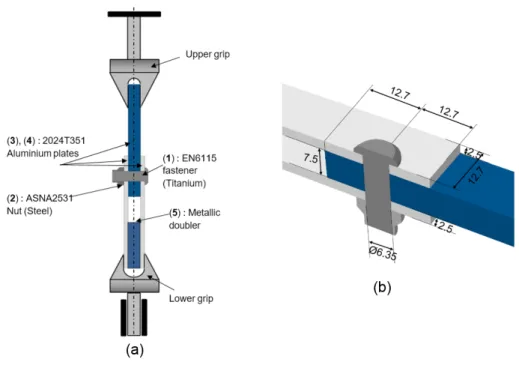
The considered joints are composed of representative aerospace joints, the dimensions and the overview of the mounting are described in Figure 2. It includes the following elements: EN6114-K4 Ta6V titanium fasteners with a nominal diameter of 6.35mm (Ref 1, Figure 2), ASNA2531-4 Cadmium steel self-locking nuts (Ref 2, Figure 2) and 3 2024-T351 Aluminum joined plates: 2 external plates of thickness 2.5mm (Ref 3, Figure 2) and an internal plate of thickness 7.5mm (Ref 4, Figure 2). The distances to the edge have been chosen in accordance with Airbus Structure Design Manual and the joining operation was made without sealant.
Given the architecture of double lap joints, aluminum doublers (Ref 5, Figure 2) were included to align the directions of external forces. The length of the fastener shaft was designed to ensure the integral transmission of the bearing force. The plate’s hole diameter was manufactured to allow a very low clearance radial adjustment (between 0 and 20 μm). A chamfer has been applied to the hole sides dedicated to receive the fastener head to allow correct seating of the fastener. Finally, the surfaces of the plates were treated to incorporate oxide layer by the means of chromic acid anodizing process and paint primary protection has been applied to be as close as possible to industrial applications (Skorupa and Skorupa [25]).
Figure 2: Joint overview: Mounting (a) – close-up view of the joint and dimensions in mm (b).
2.6- Static Tests results:
Figure 3 shows the load-displacement curves obtained from static tests, performed on low, medium and high preload loaded specimens. It is noted that the resulting force-displacement curves are quite similar, with a more pronounced preload effect on the yield load than on the ultimate load. Thus, the preload value has a neglected impact on the ultimate load and the ultimate displacement of the joint.
Figure 3: Experimental static tests results of the joint of Figure 2.
The observed failure mode is the external plate net section failure, in accordance with the analytical and experimental observations of Bickford [3] and extended by Guillot [13]. This failure mode indicates that the strength of the joint is mainly determined by the working section of the joined plates. The results of these tests are therefore in agreement with the conclusions drawn by Dang Hoang et al. [10] and Chessa et al. [8] concerning the influence of axial preload on the static behavior of the joint. The slight increase in elastic limit is mainly due to the difference in stiffness between the adhesion phase, i.e. when the external loading is transferred entirely by friction, and the sliding phase, i.e. when the bearing capacity of the fastener contributes to the load transfer, given that the transition between these two phases is directly related to the preload force applied. Finally, concerning the negligible effect of preload on the
ultimate load of the joint, once the macro-slipping exceeded, the bearing capacity takes gradually over the loading transmitted through friction interfaces, leading to plasticization of fastener shaft and complete preload loss.
2.7- Fatigue Tests results:
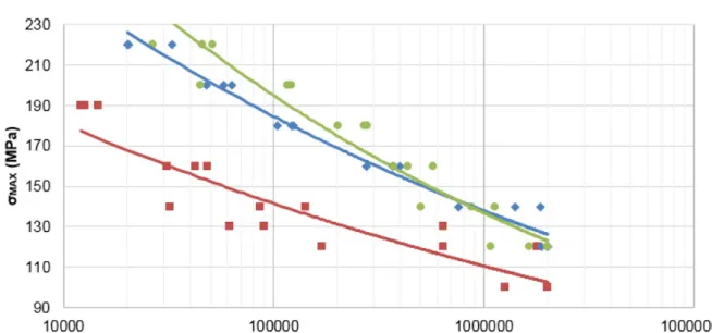
S-N data and Wöhler curves resulting from fatigue tests are given in Figure 4 and Table 1 summarizes the evolution of the admissible stress for 105 cycles as a function of the applied
preload. It is noted that the improvement of the fatigue life is very significant during the transition from 5.9 to 11.7kN, and a little less significant when increasing preload from 11.7 to 17.6kN. One can also notice that the result’s dispersion is more significant at low preload (5.9kN), which is probably related to the tooling that has been used to enable the iterative tightening process: indeed, the limit of the screwdriver used is estimated to be about 5.5kN. Contrary to the negligible preload effect on the static behavior of the reference joint, the observed results show a beneficial effect of the preload on fatigue life of fastened joints. Therefore, the results are showing the same tendencies that the ones highlighted by the work of Minguez and Vogwell [19] as well as Shankar and Dhamari [24].
Figure 4: S-N data and Wöhler curves with regard to preload.
Preload (%UTS) 25 50 75
Stress for 105
cycles(MPa) 135 184 194
Variation (%) - +37 +44
Table 1: Evolution of AFI with regard to preload.
The failure modes are also affected by the level of preload introduced. It is found that the fatigue crack initiation point migrates from the specimen’ net section for low preload levels to the specimen’ gross section for high preload levels (Figure 5). This change in failure mode indicates that the force distribution and the fastener-plate interactions are affected by preload and shows that a high level of preload allows to protect the stress concentration area and to initiate the failure outside of the compression zone, created through axial preload.
Figure 5: Failure modes in relation to preload of the joint of Figure 2.
Subsequent to fatigue tests, observation of the interface between plates using optical microscopy means shows that the tangential contact generated through preload has differently affected the overall contact zone (Figure 5). Indeed, a relatively wide contact zone can be observed in which it is possible to note a degradation of the initial surface state which is manifested by a paint stripping, which is synonymous to a high contact pressure conjugate to the cycles of tangential micro slip imposed by the external loading.
3- Numerical approach
Subsequent to the experimental findings reported in the previous section, the numerical approach, based on finite elements method, has been developed as a complementary analysis to assess, confirm and predict preloaded joints behavior that has been described up to now.
3.1- Modeling set-up
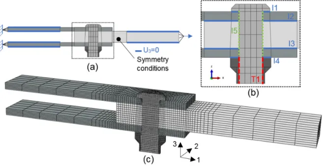
A numerical model, representative of experimental specimens, has been developed to quantify in a global way the effect of preload. Figure 6 presents a cross-sectional view of the reference joint. Essential geometrical details have been integrated into the numerical models such as the head radii, plate chamfer and the nut recess in order to ensure a good distribution of the preload in the joint and a correct estimation of the mechanical stresses in high stress concentration areas (namely under-head area and first engaged threads). A 3D numerical model has been developed under Abaqus and solved using the implicit solver. The static loading history consisted of three steps: a first step dedicated to preload application, applied through the bolt-load feature. The second step transforms this preload into an imposed displacement, and the third step that allows to apply external loading to the gross section of the internal plate while encastring the extremity of the external plate. Adequate boundary conditions have been imposed to match with the experimental tests: the axial displacement of a defined area of external and internal plates has been fixed, reflecting the action of machine jaws. Only a half joint has been considered with a plane symmetry conditions, thus allowing to reduce the calculation time required to perform the structural analysis.
Figure 6: Finite element model – boundary conditions (a), interactions (b) and mesh (c).
Aluminum material test data has been used to model the behavior of plate’s materials using linear isotropic hardening law (plastic data were extracted from MMPDS [20]). The materials of the other parts were modeled with an elastic behavior whose characteristics are detailed in Table 2.
Joint components
Fastener Nut Plates
Material Titanium Steel Aluminium
Young Modulus (GPa) 116 210 70
Poisson ratio () 0.30 0.30 0.33
Table 2: Elastic properties of considered materials.
3.2- Contact and interactions
Figure 6 shows the different interactions that has been considered between the different elements of the joint to account for the contact conditions. The interactions I1, I4 are reflecting the contact conditions between the fastener/nut and the external plates. A tangential and normal behavior has been considered, with a friction coefficient of 0.2. The same type of contact interaction has been considered for interactions I3/I4, representing the contact between plates, but with a friction coefficient of 0.4.The interaction I5 stands for the normal contact between the plate’s bores and the fastener shank, and the constraint T1 representing the fastener/nut contact has been considered as a tie constraint. This constraint couples all the degrees of freedom of the two surfaces in contact to guarantee the integral transmission of the movements [11]. The study performed by Montgomery [21] shows that a tie constraint condition between the fastener and the nut allows to correctly represent the distribution and the amplitude of the generated stresses by preload, and is substantially equivalent to the case where the full geometry, including threads representation and contact interactions between the fastener and the nut is considered.
The surface-to-surface discretization method was used because it limits the penetration between the surfaces in contact and allows to obtain more accurate results than the node-to-surface formulation. This observation was also shown by McCarthy et al. [18] who pointed out that the node-to-surface discretization method generated an erroneous radial deformation field. In general, the master surfaces have been assigned to the surfaces of the most rigid
instances in order to exclude penetration slave surface into master surface. The contact surfaces have been decomposed into several surfaces to ensure continuity of surface normals. The considered mesh consists essentially of C3D8R elements type: 8-node 3D continuum elements, with reduced integration. The choice of this element type was motivated by various numerical studies (Maximov et al. [17]) and given the fact that the accuracy/calculation time of this element type is suitable for the study. Particular attention has been paid to the partitioning of the parts to have a mesh set and to have a continuity of the stress fields from one part to the other.
3.3- Mesh convergence
Given the interest in determining preload effect on mechanical stresses then performing numerical fatigue life analysis, ensuring that the results are not affected by the mesh size is primordial. For this purpose, a mesh convergence study has been conducted. Figure 7 shows the curve representing the stress concentration factor, representing the maximal stress at stress concentration point (named A, shown in Figure 7) divided by the stress in the gross section against mesh density.
Figure 7: Mesh convergence analysis.
The stress concentration coefficient K is determined at point A as a function of the size of the elements (ratio S/R). The results obtained lead us to choose a ratio between the hole edge mesh size S and the hole radius R equal to 0.1. Local mesh refinement has been applied to the area close to the hole, whilst larger elements has been applied to the remaining plate material.
3.4- Model global validation under static loading
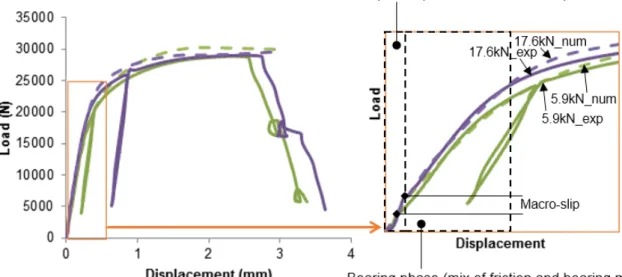
First level numerical validation was dedicated to the global response of the joint under static loading. Figure 8 shows the numerical / experimental comparison of the behavior of the reference joint under static loading (for reasons of readability, only 2 of the 3 tested preload levels are displayed). The numerical model makes it possible to accurately predict the behavior of the joint, whether in the elastic domain or the plastic domain. Stiffness of the joint is correctly predicted either for low and high preload levels, the characteristic data of the static resistance of the joint, including elastic and plastic stiffness’s, macro-slipping load and displacement and yield load shows also good correlation.
It is therefore visible that for relatively low external loads, increasing the preload and thus the macro-slipping load has the noticeable effect of making the joint work mainly in the adhesion phase, characterized by the greatest stiffness, this effect consequently help to increase the durability of the joint given that cyclic loads, leading to high cycle fatigue lives are relatively low.
Figure 8: Simulated and experimental load displacement curves under a static loading.
Analysis of friction formulation law to represent the tangential behavior has also been performed to choose the most reliable friction law. It was found that the use of the Lagrange type formulation acts mainly on the adhesion phase: the stiffness of this phase is 10 to 15% higher than that produced by the classical penalty formulation. In terms of computation time, calculations using a Lagrange multiplier law tend to diverge for high preload, probably due to the nonlinearity generated by the change of status between slip and adherence of the nodes in contact. For lower preload, the Lagrange multiplier convergence rate is significantly lower than the standard penalty method. On the other hand, considering the exponential type law, including static and kinetic friction coefficients, the main effect was linked to the transition between adhesion and bearing phases and shows a gradual decrease in carried load, according to the coefficients of the equation under consideration. Nevertheless, for radial clearance values less than 30μm, it has been observed that the exponential law has a behavior that is substantially identical to the standard penalty laws. For these reasons, the isotropic penalty formulation will be considered for the rest of the study.
In addition, the static tests allow through the identification of the macro-slipping load and displacement, to identify and to confirm the values of global friction coefficient used between the plates.
3.4- Effect of preload
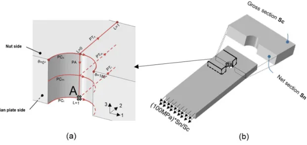
In order to assess the stress distributions in the joint, following the introduction of several preload values and under an external stress of 100MPa, calculated on the net section of the specimen (see Figure 9), seven paths were selected as described in Figure 9.
Figure 9: Definition of stress distribution paths (a), definition of applied load on gross section (b).
This aim of this section is to analyze the mechanical stresses along the most critical paths of the joined plates in order to better understand the influence of the preload on the mechanical loading transferred through the joint.
Figure 10: Evolution of the stresses σ11 along the paths, PA, PCi and PTi as a function
Figure 10 shows the evolution of the stresses σ11 through 3 selected critical paths for different
levels of preload. Looking at the evolution of the stresses σ11 along the path PA, it is observed
that the longitudinal stress remains substantially high for low preloads. Increasing the preload magnitudes decreases in a significant way the magnitudes of longitudinal stress, and this decrease occurs through the hole thickness of the external plate. Thus, the stresses obtained at the edge of the hole at the interface between the plates depend strongly on the level of preload with a significant decrease between a low preload and a high preload.
Analysis of load transfer modes, realized through monitoring contact forces through the different contact surfaces, confirms the observed tendency: through the application of high preload values, friction mode is used to transfer a high amount of external load, allowing to reduce the contribution of bearing mode, and thus reducing the stress concentration factor. Analysis of failed specimens shows that failure mostly occurs at the interface between external and internal plates, and this was independent of the preload level and joint architecture. Analysis of stresses evolution through the paths PTi and PCi, 2 paths that are located on the interface, is therefore considered and shown in Figure 10. The evolution of stresses σ11 along
the path PTi and PCi confirm the tendency highlighted on PA path: stress concentration at point A, at the edge of a hole (for L = 0 or for θ = 90°), is very high for null or low preloads. Radially, the longitudinal normal stress tends towards a horizontal asymptote when moving away from the hole edge, whatever the preload. At the edge of a hole, the evolution of the stress σ11 as a function of the preload is significant: at zero preload, a high value of tensile
stress is measured which illustrates the phenomenon of stress concentration. When the preload increases, the value at the edge of the hole evolves very substantially and becomes much lower at high preload. Indeed, the axial compression stresses introduced in the preload phase make it possible to reduce the value of σ11 when the external force is introduced for a
sufficiently high preload. Finally, the stresses analysis has also been conducted for the remaining paths and indicates the same tendencies observed for PTi and PCi paths.
3.5- Extension to fatigue loading
The numerical model has been extended to assess the fatigue behavior: subsequent to preload application (from t=0s to t=1s) and preload maintain (t=1s to t=2s), cyclic loading has been applied with the aim of evaluating the main critical values leading to fatigue crack initiation (t=2s to t=13s).
For most of the existing fatigue estimation criteria dedicated to metallic materials and structures, it is possible to state three observations (Qilafku et al. [22]):
- The fatigue life depends strongly on the shear stress variation amplitude. It decreases when the maximum amplitude of shear variation increases.
- The fatigue life is not very sensitive to the mean value of the shear stress.
- The fatigue life depends strongly on the value of the maximum hydrostatic pressure, which is equal to the average of the three normal stress components. A compression state (corresponding to a negative hydrostatic pressure) substantially increases the duration of fatigue crack initiation.
These different qualitative findings seem to be accepted by specialists and have led to many criteria (Susmel [27]). Indeed, the aim of this section is to evaluate the effect of preload on the two following variables: hydrostatic pressure and amplitude of shear stress variation.
The evolution of the hydrostatic pressure at stress concentration point (point A, Figure 9) has been plotted in Figure 11 for an external loading of 100MPa. Compressive axial stresses, introduced through preload, considerably modify the magnitude of the hydrostatic pressure
throughout the loading cycle, leading to negative mean and maximal hydrostatic pressure through the loading cycle, this reduction in hydrostatic pressure substantially increases the duration to fatigue crack initiation.
Figure 11: Evolution of the hydrostatic pressure during the loading cycle for two preload levels: 5.9 and 17.6kN.
Loading paths corresponding to the shear stress variation during the fatigue cycle are plotted in Figure 12 for two preload levels: 5.9 and 17.6kN and for an external loading of 100MPa. The calculation of the shear stress amplitude was performed on each increment of loading, by determining the critical plane (P1 to P11, corresponding to 11 increments of loading) and plotting the shear stress variation through it. The same axis limits were selected to allow the visualization of the changes in terms of amplitude but also in terms of shape. The loading paths thus have a more refined and less extended shape under the effect of a high preload value, and the maximal amplitude of the shear stress variation 𝜏𝜏𝑎𝑎,𝑚𝑚𝑎𝑎𝑚𝑚 decreases, leading to a higher
Figure 12: Plot of loading paths corresponding to shear stress variation for two preload levels: 5.9 and 17.6kN.
3.6- Application of SWT and Crossland criteria
In double lap fastened joints, the stress and strain distribution near the bolt hole is multiaxial as a result of preload and external loading. Therefore, in this study, fatigue life prediction was performed using Crossland and SWT method. The choice of these two methods was motivated by previous research studies, stating that these criteria provides better calculation accuracy than other methods for a multi-axial stress state problem (Duprat et al. [12]).
The SWT criterion, first proposed by Smith et al. [26] incorporates both cyclic strain range and maximum stress and was selected because it had the capability to predict multi-axial fatigue life (fatigue life due to complex stress states where the three principal stresses are non- proportional or whose directions change during the loading cycle). The equation (1) below presents the SWT formula that has been used:
∆𝜀𝜀
2 𝜎𝜎𝑚𝑚𝑎𝑎𝑚𝑚= (𝜎𝜎𝑓𝑓′)²
𝐸𝐸 (2𝑁𝑁𝑓𝑓)2𝑏𝑏+ 𝜎𝜎𝑓𝑓′𝜀𝜀𝑓𝑓′(2𝑁𝑁𝑓𝑓)𝑏𝑏+𝑐𝑐 (1) Where ∆𝜀𝜀2 is the maximum principal strain amplitude, 𝜎𝜎𝑚𝑚𝑎𝑎𝑚𝑚 is the maximum stress on the
maximum principal strain plane, E is the elastic modulus, Nf is the number of cycles to crack
nucleation under a certain stress and strain level, 𝜎𝜎𝑓𝑓′ (=475MPa) is the fatigue strength
coefficient, 𝜀𝜀𝑓𝑓′ (=0.27) is the fatigue ductility coefficient, b (=-0.125) is the fatigue strength
exponent and c (=-0.595) is the fatigue ductility exponent.
The Crossland criterion (Crossland [9]) is a stress based multiaxial fatigue criterion which uses the second invariant of deviatoric stress tensor and maximum hydrostatic pressure in its equation (2).
�𝐽𝐽2,𝑎𝑎+ 𝜆𝜆𝜎𝜎𝐻𝐻,𝑚𝑚𝑎𝑎𝑚𝑚= 𝜎𝜎𝑓𝑓′(2𝑁𝑁𝑓𝑓)𝑏𝑏 (2)
Where J2,a is the amplitude of second invariant of deviatoric stress tensor, σH,max is the
maximum value of the hydrostatic pressure and 𝜆𝜆 is a material dependent constant. Given that components of the stress tensor are not proportional to loading and the principal directions vary during the loading, the amplitude of second invariant of deviatoric stress tensor has been replaced by the maximum amplitude of equivalent shear stress variation, thus allowing for more adapted calculations. Specific details on this calculation technique has been developed in previous research (Benhaddou et al., [2]), leading to the main equation used to calculate the fatigue life which is reported in the equation (3).
𝑁𝑁𝑓𝑓= 105(𝑇𝑇 𝐴𝐴𝑁𝑁
𝑒𝑒𝑒𝑒,𝑎𝑎,𝑚𝑚𝑎𝑎𝑚𝑚 + 𝐵𝐵𝑁𝑁.𝜎𝜎𝐻𝐻,𝑚𝑚𝑚𝑚𝑚𝑚)
𝑝𝑝
(3) 𝐵𝐵𝑁𝑁(=0.875), 𝐴𝐴𝑁𝑁(=179.4) and 𝑝𝑝(=5) were given by two fatigue tests (at R=0.1 and R=-1) of the
considered material and considering that for different loading ratios R on a logarithmic diagram (Log (Stress), Log (Fatigue life) forms a network of parallel straight lines of slope –p.
The estimated and the experimental fatigue lives are plotted in Figure 13 for tested specimens with preload values equal to 5.9, 11.7 and 17.6kN respectively. The horizontal axis represents the experimental life and the vertical axis represents the estimated life. Both axes are in log scale. The solid line indicates that the estimated results are equal with experimental tests results. The inner bound dashed line show an estimation in accordance with the life factor of 2. The outer bound dashed line show an estimation is in accordance with the life factor of 3.
I
t is seen that the Crossland criterion agree with the experimental tests results very well and that SWT criterion tends to slightly overestimate fatigue lives, especially at high preload level. Consequently, Crossland criterion seems more adapted to the analysis of the studied configuration of double lap bolted joints.Figure 13: Correlation between predicted and experimental fatigue life.
The fatigue crack initiation site, shown as red spots, are reported in Figure 14. A unified legend has been applied and show the modification of crack initiation site for the two criteria: at low preload level, the crack initiation site is located at the hole edge of the net section. The crack
initiation site migrates outside of the compressed area for high preload levels, leading to a gross section failure. This observation tends to confirm experimental observations reported in Figure 5.
Figure 14: Location of minimal fatigue life for the different configurations (nut side is up).
4- Conclusion
The application of controlled axial preload, through the use of innovative tightening techniques, shows that high preload levels, enhances in a very significant way the fatigue life of double lap bolted joints. The failure area was also affected by the preload levels. Numerical model, allowing to analyze the effect of preload on longitudinal tensile stresses, shows that higher preload levels allows to reduce significantly the magnitude of longitudinal tensile stresses at stress concentration areas, allowing to reduce the severity of stress concentration zones and redistribute the stresses in a more effective manner. High preload allows for the reduction of hydrostatic pressure and shear stress amplitude, leading to higher fatigue lives for most of tested configurations. Fatigue life analysis, through the application of multiaxial criteria, provides a better understanding of the effects of preloading process as a fatigue life enhancement technique of fastened joints. Thus, the successful application of Crossland criterion, either in terms of fatigue life estimation and crack position determination, can be extended to the determination of optimal preload value, but also the corresponding scatter leading to the choice of the appropriate tightening mean. Finally, the choice of an average equivalent friction coefficient and a constant preload seems in good accordance with experimental results but the detailed effect of friction and preload evolutions during fatigue testing will be discussed more thoroughly in further studies.
Acknowledgements
The authors would like to acknowledge CALMIP platform for the generous grant of computing time (project P1121).
References
[1] Abazadeh B, Chakherlou TN, Farrahi GH, Alderliesten RC. Fatigue life estimation of bolt clamped and interference fitted-bolt clamped double shear lap joints using multiaxial fatigue criteria. Mater Des 2012. doi:10.1016/j.matdes.2012.06.050.
[2] Benhaddou T, Chirol C, Daidie A, Guillot J, Stephan P, Tuery JB. Pre-tensioning effect on fatigue life of bolted shear joints. Aerosp Sci Technol 2014;36:36–43.
doi:10.1016/j.ast.2014.03.003.
[3] Bickford JH. Introduction to the Design and Behavior of Bolted Joints, Fourth Edition: Non-Gasketed Joints. CRC Press; 2007.
[4] Boni L, Lanciotti A. Fatigue behaviour of double lap riveted joints assembled with and without interfay sealant. Fatigue Fract Eng Mater Struct 2011;34:60–71.
doi:10.1111/j.1460-2695.2010.01493.x.
[5] Chakherlou TN, Oskouei RH, Vogwell J. Experimental and numerical investigation of the effect of clamping force on the fatigue behaviour of bolted plates. Eng Fail Anal 2008.
[6] Chakherlou TN, Shakouri M, Akbari A, Aghdam B. Effect of cold expansion and bolt clamping on fretting fatigue behavior of Al 2024-T3 in double shear lap joints. Eng Fail Anal 2012;25:29–41. doi:10.1016/j.engfailanal.2012.04.008.
[7] Chastel JM, Rey D. Procede pour le controle et l’asservissement de la tension d’un organe filete. WO1994013437 A1, 1994.
[8] Chessa J, Arias C, Huerta M, Beard M. A Verified and Validated Study of Quasi-Static Bolted Lap Joints. Conf. Proc. Soc. Exp. Mech. Ser., 2006.
[9] Crossland B. Effect of large hydrostatic pressures on the torsional fatigue strength of an alloy steel. Int. Conf. Fatigue Met., 1956, p. 138–49.
[10] Dang Hoang T, Herbelot C, Imad A. On failure mode analysis in a bolted single lap joint under tension-shearing. Eng Fail Anal 2012;24:9–25.
doi:10.1016/j.engfailanal.2012.03.006.
[11] Dassault Systèmes Simulia. Abaqus User Manual, Version 6.13; 2013.
[12] Duprat D, Campassens D, Balzano M, Boudet R. Fatigue life prediction of interference fit fastener and cold worked holes. Int J Fatigue 1996;18:515–21. doi:10.1016/S0142-1123(96)00044-8.
[13] Guillot J. Calcul des assemblages vissés Assemblages de pièces planes de faibles épaisseurs. Partie 2. Tech l’ingénieur Assem Fixat mécaniques; 2011.
[14] Hahn GT, Kaushik IA, Rubin CA. Structural shear joints: Analyses, properties and design for repeated loading. ASME Press ; 2005.
[15] Huang Y, Li H, Yang X, Guan Z, Li Z, Sun Y. Improving the fatigue life of 2297-T87 aluminum-lithium alloy lugs by cold expansion, interference fitting, and their
combination. J Mater Process Technol 2017;249:67–77. doi:http://dx.doi.org/10.1016/j.jmatprotec.2017.06.004.
[16] Lam YC. A comparative study on the effects of interference fit and cold expansion on the fatigue life of cracked holes. Scr Metall Mater 1993;28:191–5. doi:10.1016/0956-716X(93)90561-6.
[17] Maximov JT, Duncheva GV, Ganev N. Enhancement of fatigue life of net section in fitted bolt connections. J Constr Steel Res 2012. doi:10.1016/j.jcsr.2012.02.010. [18] Mccarthy M, Mccarthy C, Lawlor V, Stanley W. Three-dimensional finite element
analysis of single-bolt, single-lap composite bolted joints: part I—model development and validation. Compos Struct 2005;71:140–58. doi:10.1016/j.compstruct.2004.09.024. [19] Minguez J, Vogwell J. Effect of torque tightening on the fatigue strength of bolted joints.
Eng Fail Anal 2006;13:1410–21. doi:10.1016/j.engfailanal.2005.10.012. [20] Battelle Memorial Institute. Metallic Materials Properties Development and
Standardization (MMPDS) Handbook; 2006.
[21] Montgomery J. Methods for Modeling Bolts in the Bolted Joint. Ansys User's Conf., 2002.
[22] Qilafku G, Kadi N, Dobranski J, Azari Z, Gjonaj M, Pluvinage G. Fatigue of specimens subjected to combined loading. Role of hydrostatic pressure. Int J Fatigue 2001;23:689– 701. doi:http://dx.doi.org/10.1016/S0142-1123(01)00030-5.
[23] Schijve J. Fatigue of Structures and Materials. Springer; 2008.
[24] Shankar K, Dhamari R. Fatigue behaviour of aluminium alloy 7075 bolted joints treated with oily film corrosion compounds. Mater Des 2002;23:209–16. doi:10.1016/S0261-3069(01)00060-7.
[25] Skorupa A, Skorupa M. Riveted lap joints in Aircraft fuselage. Springer; 2012.
[26] Smith KN, Topper T, Watson P. A stress–strain function for the fatigue of metals (stress-strain function for metal fatigue including mean stress effect). J Mater 1970;5:767–778. [27] Susmel L. Multiaxial notch fatigue.Woodhead Publishing; 2009.
[28] Taghizadeh H, Chakherlou TN, Ghorbani H, Mohammad A. Prediction of fatigue life in cold expanded fastener holes subjected to bolt tightening in Al alloy 7075-T6 plate. Int J Mech Sci 2015;90:6–15. doi:http://dx.doi.org/10.1016/j.ijmecsci.2014.10.026.
[29] Wagle S, Kato H. Ultrasonic detection of fretting fatigue damage at bolt joints of aluminum alloy plates. Int J Fatigue 2009;31:1378–85.
doi:10.1016/j.ijfatigue.2009.03.017.
[30] Yongshou L, Xindang H, Xiaojun S, Jun L, Zhufeng Y. Analytical and experimental investigation of fatigue and fracture behaviors for anti-double dog-bone riveted joints. Eng Fail Anal 2010;17:1447–56. doi:10.1016/j.engfailanal.2010.05.006.
Highlights
- Effect of axial preload on double lap fastened joints durability has been studied.
- Innovative iterative tightening technique has been used to achieve an accurate preload level. - High preload has a negligible effect on static life and beneficial effect on fatigue life.
- Numerical model allows to explain experimental findings through analysis of fatigue-linked parameters. Fatigue life analysis shows that Crossland criteria is well adapted for double lap fastened joints durability prediction.