T
T
H
H
È
È
S
S
E
E
En vue de l'obtention du
D
D
O
O
C
C
T
T
O
O
R
R
A
A
T
T
D
D
E
E
L
L
’
’
U
U
N
N
I
I
V
V
E
E
R
R
S
S
I
I
T
T
É
É
D
D
E
E
T
T
O
O
U
U
L
L
O
O
U
U
S
S
E
E
Délivré par Institut National Polytechnique de Toulouse (INP Toulouse) Discipline ou spécialité : Réseaux, Télécoms, Systèmes et Architectures
JURY
Christian FRABOUL, lNP Toulouse - IRIT Laurent GEORGE, Université Paris-Est - LIGM Nicolas NAVET, Université du Luxembourg - LASSY
Frédéric RIDOUARD, Université de Poitiers- LIAS Jean-Luc SCHARBARG, lNP Toulouse - IRIT Ye-Qiong SONG, Université de Lorraine - LORIA Yvon TRINQUET, Université de Nantes - IRCCyN
Ecole doctorale : Mathématiques Informatique Télécommunications (MITT) Unité de recherche : IRIT - Institut de Recherche en Informatique de Toulouse
Directeur(s) de Thèse : Christian FRABOUL - Jean-Luc SCHARBARG Rapporteurs : Laurent GEORGE - Ye-Qiong SONG
Présentée et soutenue par Xiaoting Li Le jeudi 19 septembre 2013
Titre : Worst-case delay analysis of real-time switched Ethernet networks with flow
Acknowledgement / Remerciements
La présente étude n’aurait pas été possible sans le bienveillant soutien de certaines personnes. Et je ne suis pas non plus capable de dire dans les mots qui conviennent, le rôle qu’elles ont pu jouer à mes côtés pour en arriver là.En premier lieu, je tiens à remercier mes directeurs de thèse, Christian Fraboul et Jean-Luc Scharbarg, professeurs à l’INP-ENSEEIHT et chercheurs à l’Institut de Recherche en Informatique de Toulouse (IRIT, UMR 5505 du CNRS), pour m’avoir guidée, encouragée, conseillée, fait beaucoup voyager pendant quatre ans tout en me laissant une grande liberté. Au travers de nos discussions, ils m’ont apporté une compréhension plus approfondie des divers aspects du sujet.
Yvon Trinquet m’a fait l’honneur de présider le jury, qu’il soit remercié pour son intérêt pour mon travail. J’adresse mes sincères remerciements à Laurent George et Ye-Qiong Song qui ont accepté de rapporter cette thèse, ainsi qu’à Nicolas Navet et Frédéric Ridouard pour l’avoir examinée.
Durant ces quatre ans, j’ai eu la chance de bénéficier de l’aide de nombreux chercheurs. Parmi les contributeurs à ce travail de thèse, je remercie chaleureusement Henri Bauer, chercheur à l’Université de Poitiers, pour ses travaux antérieurs et son aide désintéressée. Je remercie également son collègue Frédéric Ridouard, pour les échanges fructueux que nous avons en-tretenus. J’en profite aussi pour saluer Katia Jaffres-Runser, chercheur à l’INP de Toulouse, pour son aide pendant la rédaction de ma thèse.
Ensuite je tiens à remercier tous les personnels de l’équipe IRT à l’IRIT, André-Luc Beylot, Emmanuel Chaput, Jérôme Ermont, Julien Fasson, Katia Jaffres-Runser, Gentian Jakllari, Béatrice Paillassa, Maaike Verloop, · · · , sans qui cette thèse ne serait pas ce qu’elle est. Merci également à Sylvie Armengaud et Sylvie Eichen pour leur professionnalisme sans faille, leurs encouragements et leur assistance. Je passe ensuite une dédicace spéciale à tous les jeunes que j’ai eu le plaisir de côtoyer durant ces années à Toulouse, à savoir Abdelaziz, Adnan, Bouchra, Emilie, Fabian, Florian, Michaël, Nesrine, Raoul, Razvan, Tony, Victor, · · · . Les moments agreable que nous avons passés ensemble au bureau, dans le couloir, à la cantine, et au foyer, je les garde précieusement au fond de mon coeur.
Ma reconnaissance va à ceux qui ont plus particulièrement assuré le soutien affectif de ce travail doctoral : ma famille en Chine ainsi que Christine Fraboul. Enfin, j’adresse mille mercis à mon époux Chao, mon amour, pour tout ce qu’il me donne et tout ce qu’il m’apporte de bon depuis ces années, et à mon fils Noah, le trésor le plus précieux de ma vie!
Je vous aime profondément!
Xiaoting
Abstract
Full-duplex switched Ethernet is a promising candidate for interconnecting real-time industrial applications. But due to IEEE 802.1d indeterminism, the worst-case delay analysis of critical flows supported by such a network is still an open problem. Several methods have been proposed for upper-bounding communication delays on a real-time switched Ethernet network, assuming that the incoming traffic can be upper bounded. The main problem remaining is to assess the tightness, i.e. the pessimism, of the method calculating this upper bound on the communication delay. These methods consider that all flows transmitted over the network are independent. This is true for flows emitted by different source nodes since, in general, there is no global clock synchronizing them. But the flows emitted by the same source node are local synchronized. Such an assumption helps to build a more precise flow model that eliminates some impossible communication scenarios which lead to pessimistic delay upper bounds.
The core of this thesis is to study how local periodic flows synchronized with offsets can be handled when computing delay upper-bounds on a real-time switched Ethernet. In a first step, the impact of these offsets on the delay upper-bound computation is illustrated. Then, the integration of offsets in the Network Calculus and the Trajectory approaches is introduced. Therefore, a modified Network Calculus approach and a modified Trajectory approach are developed whose performances are compared on an Avionics Full-DupleX switched Ethernet (AFDX) industrial configuration with one thousand of flows. It has been shown that, in the context of this AFDX configuration, the Trajectory approach leads to slightly tighter end-to-end delay upper bounds than the ones of the Network Calculus approach. But offsets of local flows have to be chosen. Different offset assignment algorithms are then investigated on the AFDX industrial configuration. A near-optimal assignment can be exhibited.
Next, a pessimism analysis of the computed upper-bounds is proposed. This analysis is based on the Trajectory approach (made optimistic) which computes an under-estimation of the worst-case delay. The difference between the upper-bound (computed by a given method) and the under-estimation of the worst-case delay gives an upper-bound of the pessimism of the method. This analysis gives interesting comparison results on the Network Calculus and the Trajectory approaches pessimism.
The last part of the thesis, deals with a real-time heterogeneous network architecture where CAN buses are interconnected through a switched Ethernet backbone using dedicated bridges. Two approaches, the component-based approach and the Trajectory approach, are developed to conduct a worst-case delay analysis for such a network. Clearly, the ability to compute end-to-end delays upper-bounds in the context of heterogeneous network architecture is promising for industrial domains.
List of Abbreviations and Symbols
Abbreviations:
AFDX Avionics Full-DupleX Ethernet ARINC Aeronautical Radio, Incorporated BAG Bandwidth Allocation Gap CAN Controller Area Network CPU Central Processing Unit CRC Cyclic Redundancy Check
CrossedS an offset assignment considering the number of crossed switches based on PairAssign (see PairAssign)
CrossedSSA an offset assignment considering the number of crossed switches based on SingleAssign (see SingleAssign)
CSMA/CD Carrier Sense Multiple Access with Collision Detection ECU Electronic Control Unit
EDF Earliest Deadline First
EPL Ethernet Powerlink
ES End System
ETE End-To-End
ETH Ethernet network
EtherCAT Ethernet for Control Automation Technology FCFS First Come First Served
FIFO First In First Out
FIP Factory Instrumentation Protocol
FP Fixed Priority
FP/EDF Fixed Priority/Earliest Deadline First FP/FIFO Fixed Priority/First In First Out gcd greatest common divisor
GCD dissimilar offset assignment
GCDMinus a near-optimal offset assignment heuristic considering the minus value of the greatest common divisor of periods of a pair of flows
lcm least common multiple IdealAssign an ideal offset assignment
IEEE Institute of Electrical and Electronics Engineers
IP Internet Protocol
6
MostLoad an offset assignment considering the load at output port based on PairAssign (see PairAssign)
MostLoadSA an offset assignment considering the load at output port based on SingleAssign (see SingleAssign)
Opt an optimal approach based on the modified Network Calculus approach and the modified Trajectory approach
PairAssign offset assignments of near-optimal offset assignment heuristics and GCD (see GCD)
PC Purely CAN flows in a heterogeneous network PE Purely Ethernet flows in a heterogeneous network
PF Periodic Flow
PROFIBUS Process Field Bus PROFINET Process Field Network
QoS Quality of Service
RAGCD a near-optimal offset assignment heuristic considering the rate sum and the greatest common divisor of periods of a pair of flows RateAdd a near-optimal offset assignment heuristic considering the rate sum
of a pair of flows
RC Remote CAN flows in a heterogeneous network
RMGCD a near-optimal offset assignment heuristic considering the maximum rate and the greatest common divisor of periods of a pair of flows
RT Real Time
SAC Safe Arrival Curve
SF Sporadic Flow
SingleAssign an offset assignment oringinally designed for automotive TCnet Time-Critical Control Network
TCP Transmission Control Protocol
TCP/UDP/IP Transmission Control Protocol/User Datagram Protocol/Internet Protocol TDMA Time Division Multiple Access
TTE Time-Triggered Ethernet
UDP User Datagram Protocol
UTP Unshielded Twisted Pair
VL Virtual Link
7
Symbols:
αi the arrival curve of flow τi
α∗ the arrival curve of output flow
αh the arrival curve of the aggregated flow at the output port h
αIPh
k the arrival curve of the aggregated flow of input link IP
h k
αhGx the Safe Arrival Curve of a flow set Gx at the output port h
ahfi the arrival time of a frame fi at the output port h
Ai,j the workload interval for flow τj delaying flow τi
Ai,j,k the constrained workload interval of τk to delay τi
β the service curve
bph a busy period at the output port h without idle time during it
Bi,t the sum from Term3.3 to Term3.6
BAGi the Bandwidth Allocation Gap value of VL vi
Bslow
i the computation range for the Trajectory approach
Brdgi a brigde connecting a CAN bus and the Ethernet backbone in a
heterogeneous network
γri,bi the arrival curve of a leaky bucket flow model, where ri is the leak rate and bi is the burst
compx a component in a heterogeneous network which has its own bandwidth and
manages its flows based on a local scheduling
CET H the maximum transmission time of an Ethernet frame encapsulating
CAN frames in a heterogeneous network
Ci the frame transmission time of flow τi
Cih the frame transmission time of τi on node h
Ccompx
i the frame transmission time of flow τi at the component compx in a
heterogeneous network
CANi A CAN bus
desti the destination node of flow τi
Dhpi the delay of flow τi generated by interference flows in hpi Dcompx
maxi the maximum delay of flow τi generated in component compx of a heterogeneous network
Dcompx
mini the minimum delay of flow τi generated in component compx of a heterogeneous network
Dspi the delay of flow τi generated by interference flows in spi δi the delay of flow τi generated by flows in δi due to FIFO with
non-preemptive effect
∆hi a factor considering the frame serialization with reachable frame sequences in the pessimism analysis
∆h
i,t the frame serialization factor
fi one frame of flow τi
fi,j the jth frame of flow τi
8
f irsti the source node of flow τi
f irstj,i the first output port where a competing flow τj crosses the flow τi
f irstF Pj,i the first shared FP output port of flow τi and flow τj along the path Pi in a heterogeneous network
Gx the xth subset containing dependent flows
h a node of a network
h(α, β) the maximum horizontal deviation between α and β
hpi a set of flows having higher priorities than flow τi
IPhk the set of flows crossing the kth input link of h
ji the release jitter of flow τi
Ji the maximum release jitter of flow τi
Jcompx
i the maximum release jitter of flow τi at the component compx in a
heterogeneous network
lkh the duration of sequence seqhk without its first frame
lmax the maximum frame length of a Ethernet frame
lmin the minimum frame length of a Ethernet frame
lastF IF Oi,j the last share FIFO output port of flow τi and flow τj along the path Pi in a heterogeneous network
lasti the last visited output port of flow τi
lpi a set of flows having lower priorities than flow τi
Lmax the maximum processing delay when a frame crosses a link
Lmin the minimum processing delay when a frame crosses a link
LDi the transmission delay on links of flow τi along the path Pi
Mih the earliest possible starting instant of bph for the flow τi
M Dhi,j the minimum duration from τi to τj at the output port h
nB the number of bridges visited by a studied flow in a heterogeneous network
nBout the number of bridg ourpur ports connceting Ethernet visited by flow τi in a heterogeneous network
nS the number of switches visited by a studied flow in a heterogeneous network
Ni an end node of a real-time switched Ethernet
NB the maximum number of CAN frames encapsulated within an Ethernet
frame at a bridge in a heterogeneous network
Oi the offset of flow τi
OPh the output port link of h
pi the priority of flow τi
pcompx
i the priority of flow τi at the component compx in a heterogeneous network
p(h) the last frame of the busy period bph
PCFlasti i,t
the pessimism upper bound of the delay of flow τi generated by competing
flows in the pessimism analysis
PCTlasti i
the pessimism upper bound of the delay of flow τi generated by busy period
transition in the pessimism analysis
P
Si,tlasti the upper bounded pessimism introduced by the computation of frame
serialization for flow τi in the pessimism analysis
Pi the path of flow τi |Pi| the length of path Pi
9
rlkh a reachable duration of a frame sequence seqhk without its first frame in the pessimism analysis
R the transmission rate of the network
Rc the total constant cost in switches and in bridges a studied flow in a
heterogeneous network
RCAN the bandwidth of a CAN bus in a heterogeneous network
RET H the bandwidth of the Ethernet backbone in a heterogeneous network
Ri the end-to-end delay of flow τi
Rtrs the tranmission cost of a studied flow along its path in a heterogeneous network
R(t) input function of flow traffic over time t
R∗(t) output function of flow traffic over time t
RSi,t,x the maximum workload generated by the interference set Gx
seqhk the frame sequence of IPhk
shpi j ∈ shpi if pj > pi and τj shares pure FP or both FP and FIFO scheduling
policies with τi in a heterogeneous network
slpi j ∈ slpi if pj < pi and f irstj,i is with FP scheduling in a heterogeneous
network
sspi j ∈ sspi if pj = pi; or if pj < pi and f irstj,i is with FIFO scheduling in
a heterogeneous network
sl the switching latency delay of a switch
slowi the slowest node visited by τi on its path Pi
slowj,i the slowest node visited by τj on the path Pi
spi a set of flows having the same priority as flow τi
Smaxh i the maximum delay experienced by a frame of flow τi from its source
node f irsti to output port h
Sh
mini the minimum delay experienced by a frame of flow τi from its source node f irsti to output port h
SET H the maximum size of an Ethernet frame encapsulating CAN frames in a
heterogeneous network
SDi the total switching lantency delay of flow τi along the path Pi
τi a real-time switched Ethernet flow
τcompx
i the input flow of flow τi at the component compx in a heterogeneous network
TB a constant cost used in a brigde for frame encapsulation/decapsulation
in a heterogeneous network
Ti the period of flow τi
Tcompx
i the period of flow τi at the component compx in a heterogeneous network
U Pi the pessimism upper bounds of the worst-case ETE delay computation of the
flow τi using the Trajectory approach
U Ri the underestimation of the worst-case ETE delay of flow τi using the classical
10
U RCFlasti i
the lower bounded delay of flow τi generated by competing flows in the
pessimism analysis
U R
CTilasti the lower bounded delay of flow τi generated by busy period transition in
the pessimism analysis
U R
Slastii a reachable value of frame serialization effect in the pessimism analysis
vi a VL in the AFDX network
Wlasti
i,t the latest starting time of a frame fi of τi at its last visited output port lasti
W D the maximum waiting delay of a CAN frame pending in a bridge output port in a heterogeneous network
W Di the total waiting delay in the output buffers of flow τi along the path Pi
Mathematics Symbols:
(a)+= max(a, 0)
Contents
Acknowledgement / Remerciements 1
Abstract 3
List of Abbreviations and Symbols 5
General Introduction 1
1 Worst-case delay analysis of switched Ethernet networks 7
1.1 Introduction . . . 7
1.2 Context of real-time Ethernet . . . 8
1.2.1 Evolution . . . 8
1.2.2 Real-time Ethernet solutions . . . 9
1.3 Real-time switched Ethernet network . . . 10
1.3.1 Network model . . . 11
1.3.2 Flow model . . . 12
1.3.3 A real-time switched Ethernet example: AFDX network . . . 13
1.4 End-to-end delay analysis on a real-time switched Ethernet . . . 13
1.4.1 End-to-end delay . . . 14
1.4.2 Minimum end-to-end delay . . . 16
1.4.3 Maximum end-to-end delay . . . 16
1.5 Existing approaches for worst-case delay analysis . . . 19
1.5.1 Simulation . . . 20
1.5.2 Model-checking . . . 20
1.5.3 Network Calculus . . . 20
1.5.4 Trajectory approach . . . 21
1.6 Temporal constraints of dependent flows . . . 22
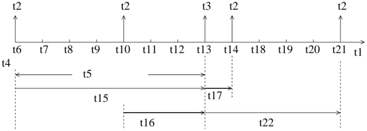
1.6.1 Minimum duration . . . 22
1.6.2 Computation of minimum duration . . . 24
1.7 Conclusion . . . 29
2 Modified Network Calculus approach integrating minimum duration con-straints 31 2.1 Introduction . . . 31
2.2 Classical Network Calculus approach . . . 32
2.2.1 Arrival curves . . . 32 11
12 CONTENTS
2.2.2 Service curves . . . 33
2.2.3 Delay computation . . . 34
2.2.4 Frame serialization . . . 35
2.2.5 Limitation of the approach . . . 36
2.3 A modified approach considering minimum duration constraints . . . 36
2.3.1 General idea . . . 36
2.3.2 Computation overview . . . 37
2.3.3 Computation of the arrival curve of dependent flows . . . 38
2.4 Application on a small network example . . . 41
2.4.1 Classical Network Calculus approach . . . 42
2.4.2 Modified Network Calculus approach . . . 44
2.5 Conclusion . . . 48
3 Modified Trajectory approach integrating minimum duration constraints 51 3.1 Introduction . . . 51
3.2 Classical Trajectory approach . . . 52
3.3 A modified approach considering minimum duration constraints . . . 58
3.3.1 General idea . . . 58
3.3.2 Computation overview . . . 59
3.3.3 Computation of the maximum workload of dependent flows . . . 59
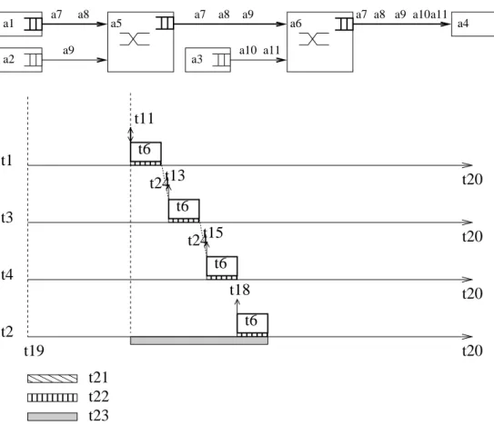
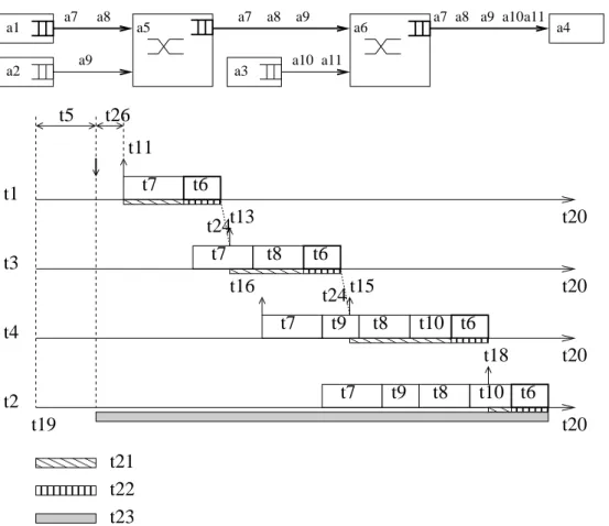
3.4 Illustration on a small network example . . . 65
3.4.1 Classical Trajectory approach . . . 65
3.4.2 Modified Trajectory approach . . . 66
3.5 Conclusion . . . 70
4 A real-time switched Ethernet example: the AFDX network 71 4.1 Introduction . . . 71
4.2 AFDX context . . . 72
4.3 Example of an offset assignment algorithm . . . 74
4.4 Worst-case delay analysis based on the modified Network Calculus approach . . 75
4.5 Worst-case delay analysis based on the modified Trajectory approach . . . 78
4.6 A comparison of the two modified approaches . . . 81
4.7 Near-optimal offset assignment for the industrial AFDX network . . . 82
4.7.1 Existing offset assignments . . . 83
4.7.2 Optimal scenario of dependent flows over the AFDX network . . . 84
4.7.3 Offset assignment algorithms in the context of AFDX network . . . 86
4.7.4 Results . . . 92
4.8 Conclusion . . . 94
5 Pessimism analysis 97 5.1 Introduction . . . 97
5.2 Pessimism analysis based on the classical Trajectory approach . . . 99
5.2.1 Review of the classical Trajectory approach . . . 99
5.2.2 Pessimism analysis of computing flows . . . 101
5.2.3 Pessimism analysis of busy period transition . . . 105
CONTENTS 13
5.2.5 Analytical method for underestimated delays . . . 115
5.2.6 Analytical method for maximum potential pessimism . . . 115
5.3 Integration of the minimum duration constraints . . . 116
5.3.1 Review of the modified Trajectory approach . . . 117
5.3.2 Illustration on the overestimation of dependent flows . . . 117
5.3.3 Pessimism analysis of the workload of dependent flows . . . 120
5.4 Application on the AFDX network . . . 121
5.4.1 Upper bounding the pessimism of the Network Calculus approach . . . 122
5.4.2 Upper bounding the pessimism of the Trajectory approach . . . 122
5.5 Conclusion . . . 124
6 Worst-case delay analysis on a heterogeneous network 127 6.1 Introduction . . . 127
6.2 Heterogeneous network architecture . . . 129
6.2.1 CAN bus . . . 129
6.2.2 Switched Ethernet backbone . . . 129
6.2.3 Heterogeneous flows . . . 130
6.2.4 Bridging strategy . . . 131
6.2.5 End-to-end delay analysis . . . 132
6.3 Component-based approach for worst-case delay analysis . . . 133
6.3.1 Component-based architecture . . . 133
6.3.2 Network Calculus approach for Non-preemptive FP Scheduling . . . 138
6.4 Trajectory approach for worst-case delay analysis . . . 139
6.4.1 Classical Trajectory approach for FP/FIFO scheduling applied to a ho-mogeneous network . . . 139
6.4.2 A modified Trajectory approach adapted to a heterogeneous network . . 143
6.5 Case study . . . 147
6.6 Improved Trajectory approach . . . 150
6.7 Conclusion . . . 153
Conclusions and Perspectives 155 A Network Calculus 161 A.1 Network Calculus . . . 161
A.2 Application on a switched Ethernet network . . . 163
A.3 Integration of frame serialization . . . 165
B Trajectory approach 169 B.1 Trajectory approach . . . 169
B.2 Application on a switched Ethernet network . . . 173
B.3 Integration of frame serialization . . . 176
List of Figures
1.1 Example of the network architecture . . . 11
1.2 An illustration of a static flow path Pi,j . . . 12
1.3 Example of mapping flows on the network architecture . . . 12
1.4 Temporal characteristics of a sporadic flow and a periodic flow . . . 13
1.5 Illustration of end-to-end delay of flow τ1 . . . 15
1.6 Illustration of minimum end-to-end delay of flow τ1 . . . 17
1.7 Illustration of end-to-end delay of flow τ1 on a possible scenario . . . 18
1.8 The end-to-end delay characteristics . . . 19
1.9 A reference network example . . . 23
1.10 Minimum durations between τ1 and τ2 at the output port of N1 . . . 23
1.11 Minimum duration between τ1 and τ2 at the output port of N1 with release jitters 24 1.12 Propagation of the Minimum Duration . . . . 25
1.13 Temporal durations from between a frame arrival of τ1 and a frame arrival of τ2 25 1.14 General case . . . 27
1.15 One possible scenario . . . 28
2.1 Recall of the network example for the Network Calculus approach . . . 32
2.2 The arrival curves of flows τ1 and τ2 at N1 . . . 33
2.3 The maximum delay generated at the output port of N1 . . . 34
2.4 Propagation of the arrival curve . . . 35
2.5 The arrival curves of flows . . . 35
2.6 Serialization of αS1 1 and αS21 . . . 36 2.7 Serialization of αS1 3 and α S1 4 . . . 36
2.8 Illustration of the burst workload at N1 . . . 37
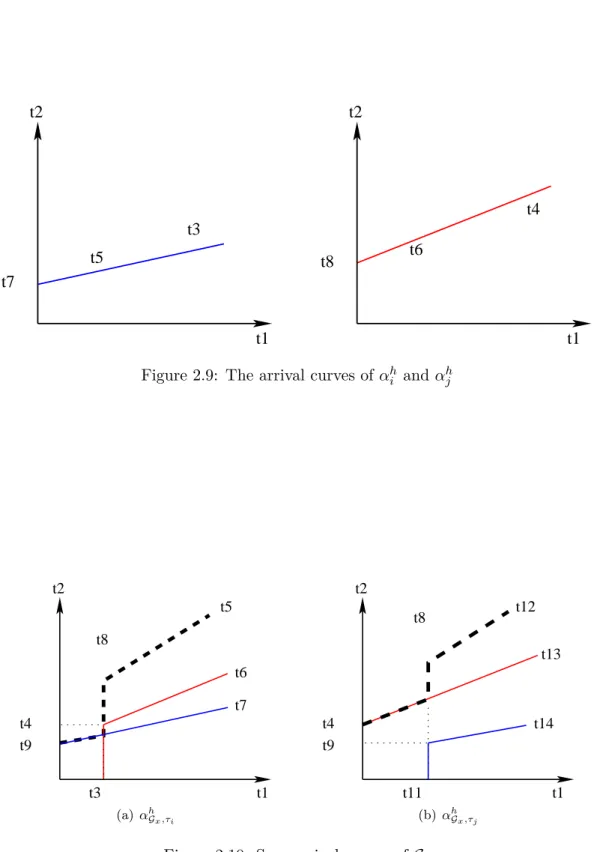
2.9 The arrival curves of αhi and αhj . . . 39
2.10 Sum arrival curves of Gx . . . 39
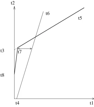
2.11 The Safe Arrival Curve of subset Gx . . . 41
2.12 The arrival curves of flows . . . 42
2.13 Maximum delay generated at S1 . . . 43
2.14 Worst-case delay of τ1 with the classical Network Calculus approach . . . 43
2.15 Sum arrival curves of G1 . . . 44
2.16 The Safe Arrival Curve of subset G1 . . . 45
2.17 The overall arrival curve αS1 . . . . 46
2.18 Comparison with the classical Network Calculus approach . . . 46
2.19 Illustration on the output port of S2 . . . 47
2.20 The illustration on R1 computed by the modified Network Calculus approach . 48 3.1 Recall of the network example for the Trajectory approach . . . 52
16 LIST OF FIGURES
3.2 Worst-case scenario corresponding to the classical Trajectory approach . . . 53
3.3 Illustration of the interval at f irstj,i . . . 54
3.4 Illustration of the interval at f irstj . . . 54
3.5 Illustration of the workload intervals of τ3 . . . 56
3.6 Illustration of the computation of R1 . . . 57
3.7 Illustration of the workload intervals of τ3 and τ4 . . . 58
3.8 An illustrative example . . . 60
3.9 Illustration of the workload intervals Ai,j and Ai,k . . . 60
3.10 Illustration of the constrained workload intervals Ai,j,k . . . 61
3.11 Illustration of the constrained workload intervals Ai,k,j . . . 61
3.12 Illustration of a possible scenario of workload interval . . . 62
3.13 Illustration of the frame shift . . . 62
3.14 Classical approach . . . 65
3.15 Modified approach . . . 65
3.16 Illustration on maximum workload curve RS1,t,2 . . . 67
3.17 Illustration on maximum workload curve RS1,t,1 . . . 68
3.18 Illustration on maximum workload curve RS1,t,3 . . . 69
3.19 Worst-case scenario corresponding to the modified Trajectory approach . . . . 69
4.1 An illustrative industrial AFDX network architecture . . . 73
4.2 Improvement of the modified Network Calculus approach . . . 76
4.3 Improvement of the modified Network Calculus approach with partial dependencies 77 4.4 Improvement of dependent flows of the modified Network Calculus . . . 78
4.5 Improvement of independent flows of the modified Network Calculus . . . 78
4.6 Improvement of the modified Trajectory approach . . . 79
4.7 Improvement of the modified Trajectory approach with partial dependent flows 80 4.8 Improvement of dependent flows based on the Trajectory approach . . . 81
4.9 Improvement of independent flows based on the Trajectory approach . . . 81
4.10 Comparative results of two approaches . . . 82
4.11 A sample AFDX network of Example 1 . . . 86
4.12 Scenarios of the VL v1 . . . 86
4.13 A small example of AFDX network of Example 2 . . . 87
4.14 Illustration of the SingleAssign with low workload . . . 88
4.15 Illustration of SingleAssign with increased workload . . . 89
4.16 Illustration of MostLoadSA with high workload . . . . 90
4.17 A small example of AFDX . . . 93
4.18 Comparison of GCD and SingleAssign . . . 93
4.19 Comparative results of IdealAssign, SingleAssign and MostLoadSA . . . . 94
5.1 Example 3 . . . 101
5.2 Worst-case scenario for τ1 of the Example 3 . . . 102
5.3 Illustration on minimum inter-arrival time between two frames of the same flow 102 5.4 Example 4 . . . 103
5.5 Worst-case scenario for τ1 of the Example 4 . . . 104
5.6 Sample network of Example 5, 6, 7 . . . 105
5.7 Worst-case scenario for τ1 of the Example 5 . . . 106
5.8 Worst-case scenario for τ1 of the Example 6 . . . 107
5.9 Illustration of ∆S1 1,t . . . 109
LIST OF FIGURES 17
5.10 Worst-case scenario for τ1 of the Example 7 . . . 110
5.11 Illustration of Lemma 2 . . . 112
5.12 Illustration of seqh0 . . . 113
5.13 Illustration of a reachable seqh0: Case 1 . . . 113
5.14 Illustration of a reachable seqh0: Case 2 . . . 114
5.15 Illustration of a reachable delay of τ1 . . . 117
5.16 Example 8 . . . 118
5.17 Illustration on minimum duration M DN5 5,6 . . . 118
5.18 Worst case scenario for τ1 in Example 8 . . . 119
5.19 Example 9 . . . 119
5.20 Worst case scenario for τ1 in Example 9 . . . 120
5.21 Upper bounded pessimism of the Network Calculus approach . . . 123
5.22 Upper bounded pessimism of the Trajectory approach . . . 124
6.1 Heterogeneous network . . . 130
6.2 Heterogeneous path for τ2 . . . 132
6.3 Hierarchical scheduling framework . . . 134
6.4 Compositional scheduling framework on an example . . . 135
6.5 Component-based approach for heterogeneous networks . . . 135
6.6 Component and interface . . . 136
6.7 Illustration of the component-based approach for flow τ2 . . . 137
6.8 Interval of flow with higher priority . . . 141
6.9 Illustration of heterogeneous scheduling policies integration . . . 145
6.10 Heterogeneous network example . . . 147
6.11 Worst-case ETE delay of pure Ethernet flows . . . 148
6.12 Worst-case ETE delay of pure CAN flows . . . 149
6.13 Worst-case ETE delay of remote CAN flows . . . 149
6.14 Worst-case ETE delay of remote CAN flows according to the path . . . 150
6.15 Example network . . . 151
6.16 Illustration on τ1 . . . 152
6.17 Worst-case ETE delay of remote CAN flows with the improved Trajectory approach153 6.18 Worst-case ETE delay of remote CAN flows of CAN1 to CAN3 and CAN1 to CAN4 with the improved Trajectory approach . . . 154
A.1 Illustration of Network Calculus . . . 162
A.2 Propagation of Network Calculus . . . 163
A.3 Illustration of Network Calculus applied to real-time switched Ethernet . . . . 164
A.4 Illustration on frame serialization . . . 166
A.5 The aggregated flow of one input link IPhk considering the frame serialization . 167 B.1 Illustration of busy period . . . 170
B.2 Illustration of the workload interval Ai,j . . . 172
B.3 An switched Ethernet network illustration . . . 174
B.4 The transmission process of frame f1 of flow τ1 . . . 174
B.5 Illustration on a node h with an output link OPh and kh+ 1 input link IPhk . . 177
List of Tables
1.1 Flow parameters of the reference network example . . . 23
1.2 Flow parameters of the reference network example with release jitters . . . 24
1.3 All the possible values of M DN1 1,2(k, l) . . . . 26
1.4 All the possible values of M DN1 2,1(k, l) . . . . 27
1.5 minimum durations of flows τ1, τ2, τ3 and τ2. . . 29
2.1 Recall of flow parameters of the network example for the Network Calculus approach . . . 32
2.2 End-to-end delay upper bounds of the reference example . . . 48
3.1 Recall of flow parameters of the network example for the Trajectory approach . 52 3.2 Minimum durations of flows τ1, τ2, τ3 and τ4 at their source nodes . . . 65
3.3 End-to-end delay upper bounds of the reference example . . . 70
4.1 BAGs and frame lengths . . . 74
4.2 VL paths lengths . . . 74
4.3 The example of offset assignment . . . 75
4.4 Improvement on burst workload at output ports of ESs and switches . . . 79
4.5 The Configuration of flows of Example 1 . . . 86
4.6 The Configuration of flows of Example 2 . . . 87
4.7 The assigned offsets based on different offset assignments . . . 91
4.8 Statistic reduction on end-to-end delay upper bounds for each offset algorithm 92 5.1 Number and percentage of paths with exact worst-case delays . . . 124
6.1 Flows in the example in Figure 6.1 . . . 131
General Introduction
Due to a limited bandwidth, the fieldbus technologies cannot cope with the increasing de-mand of data exchange of the industrial applications. Ethernet technology therefore becomes a promising candidate since it provides large bandwidth of data transmission and steadily decreasing cost. Since vintage Ethernet is not able to reach the real-time requirements, one solution considered in this thesis is based on a full-duplex switched Ethernet with traffic as-sumptions on incoming flows (traffic shaping).
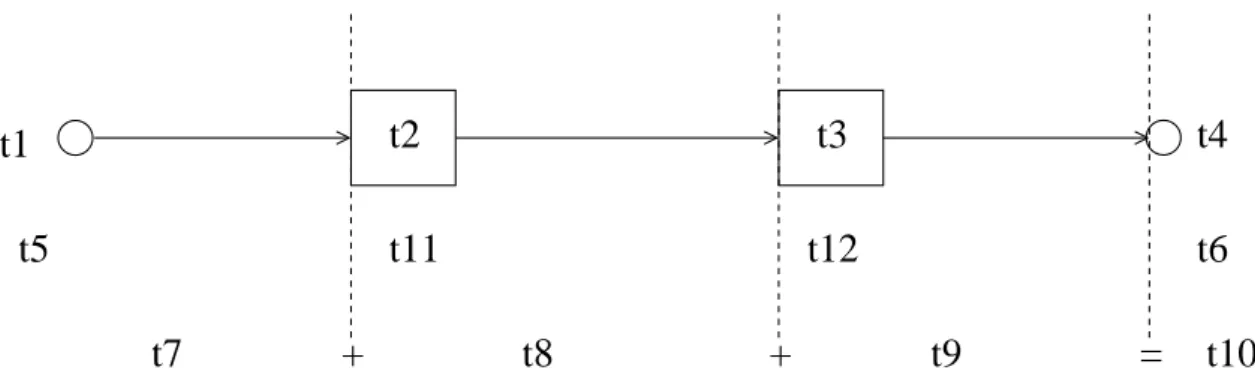
One important real-time requirement is the worst-case end-to-end (ETE) communication delay. For a full-duplex switched Ethernet network, the end-to-end communication delay of a flow transmitted in the network is the time elapsed between the generation time of one frame of the flow at its source node and the reception time of this frame at its destination node. Then the end-to-end delay is the sum of the transmission delay on each crossed link and the delay generated at each crossed switch along the path. The worst-case end-to-end delay considers the most unfavorable scenario along the path. It depends on the generation times of other flows crossing the path, and therefore it is difficult to compute the worst-case end-to-end delays of large-scale networks. One solution is to guarantee the upper bounds of the worst-case delays by worst-case delay analysis, and efforts have been dedicated to solve this problem.
There exist several end-to-end delay analysis methods for real-time switched Ethernet net-works. Simulation approach is based on the model of the network and it provides valuable informations about the delay distribution. However, worst-case delay is often a rare event that is missed by the simulation approach. Model-Checking performs an exhaustive exploration of the possible scenarios in order to calculate an exact worst-case end-to-end delay. However, it is limited to small networks due to the huge combinatorial explosion problem for large con-figuration. Network Calculus approach is a powerful method that uses arrival curves, which upper bound the arriving traffic, to describe arriving flows. It computes the maximum delay of a flow generated at each crossed switch and therefore leads to the worst-case end-to-end delay upper bound along the path. This approach is classical although it accumulates pessimism at each hop. The Trajectory approach allows a direct analysis on the worst-case scenario that can happen to a frame along its trajectory. It has been shown that this approach improves the computation of end-to-end delay upper bounds for an industrial avionics switched Ether-net Ether-network [BSF10]. Therefore, the Trajectory approach attracts increasing attention in the worst-case delay analysis.
All the worst-case delay analysis methods mentioned above consider that flows transmitted over the network are independent. This is true with flows emitted by different source nodes since there is no global clock to synchronize flows. However, each source node does have a
2 General Introduction
local clock which can synchronize its flows. It means that local flows (emitted by the same source node) can be synchronized and that periodic flows can have known offsets. Thus offset assumptions increase the knowledge about the frame arrivals of periodic flows emitted by the same source node. They help to build a more precise flow model and eliminate some impossible scenarios which lead to pessimistic computation. Hence, the study of offset constraints is an important issue which needs to be addressed in the worst-case delay analysis of switched Ethernet networks.
The subject of this thesis is to integrate the offset constraints in the worst-case delay analysis of switched-Ethernet networks. This problem is of great interest since improved worst-case delay analysis can be obtained on large scale industrial switched Ethernet network. In the first step, we identify the offset constraints among a set of periodic flows emitted by the same source node and illustrate the offset constraint and its impacts on worst-case delay computation. In the second step, two approaches, the Network Calculus approach and the Trajectory approach, are proposed to integrate these offset constraints. Therefore, these two approaches allow us to compute the worst-case delay upper bounds of a real-time switched Ethernet network with offset assumption. As a real example of real-time switched Ethernet network, the Avionics Full-DupleX switched Ethernet network (AFDX) is introduced. The two proposed approaches are applied on an industrial AFDX configuration to show the improvement of the computed end-to-end delay upper bounds. Since the proposed approaches provide us a tool to evaluate a network with offsets, we are interested in the offset assignment algorithm that leads to minimum computed end-to-end delay upper bounds for the industrial AFDX network. An optimal scenario is introduced which minimizes the worst-case delays for all the flows. The existing offset assignments are presented and evaluated by comparing the results to those obtained based on the optimal scenario.
The worst-case delay analysis leads to pessimistic delay upper bound computation. In order to investigate how pessimistic the proposed approaches are, an analytical pessimism analysis is developed based on the Trajectory approach and an upper bound of the introduced pessimism is obtained by measuring the maximum gap of a computed worst-case delay upper bound and an underestimated value of the worst-case delay.
As a future direction, a heterogeneous network architecture which combines existing field buses and a switched Ethernet is then studied. A worst-case delay analysis is tricky in such an architecture due to its heterogeneity nature (different bandwidths, scheduling policies, etc.). Two approaches are proposed to solve this problem. One is component-based approach which preserves the network properties but introduces pessimism at each component level; the other one is an adjusted Trajectory approach which unifies the heterogeneities along each path.
Main contributions of this thesis are summarized below.
• Integration of offset constraints in the Network Calculus approach and in the Trajectory approach applied to the real-time switched Ethernet network. Each source node in the switched Ethernet network has a local clock based on which the transmissions of periodic flows are not independent. Indeed, periodic flows with known offsets emitted by the same source node are dependent. A benefit of knowing the offsets is to improve the worst-case delay analysis for a switched Ethernet network
3
since it can eliminate some impossible scenarios. Existing approaches of worst-case delay analysis do not consider the offsets. In this work, we show how to integrate the offset constraints in two approaches: the Network Calculus approach [LSF10b,LSF10a,LSF10c] and the Trajectory approach. These two modified approaches allow us to improve the computation of worst-case delay upper bounds of large scale switched Ethernet networks.
• Applications of the modified Network Calculus approach and the modified Trajectory approach on an industrial avionics switched Ethernet network. The Avionics Full-DupleX switched Ethernet network (AFDX) can be seen as an example of real-time switched Ethernet. The two proposed approaches are applied to an industrial AFDX configuration. The results show that the two modified approaches improve the computation of delay upper bounds. We compare the delay upper bounds computed by these two modified approaches. Such a comparison allows us to know which approach is more suitable for such an industrial configuration. Moreover, an optimal approach is presented by choosing the tighter (smaller) computed worst-case delay between the results of the two modified approaches. Such an optimal approach provides an improved network performance evaluation by combining the two modified approaches.
• Evaluation of offset assignment algorithms for the industrial AFDX network. In the context of processor and CAN bus, there exist studies about offset assignments which lead to the maximum system performance [Goo03, GHN08]. Since the choice of offset assignment is related to a specific application, in this work, we focus on the industrial AFDX network [LSFF11]. An optimal scenario is introduced which considers infinitive durantion between frame arrivals for all the flows. The comparison between the offset assignment algorithms and the optimal scenario allows us to know which algorithm leads to better performance (smaller computed delay upper bounds) in this context as well as how far the existing algorithms are from the optimal case.
• Analysis of pessimism introduced by the Trajectory approach and formaliza-tion of computaformaliza-tion on pessimism upper bound.
The Trajectory approach guarantees the worst-case delay upper bounds of the switched Ethernet network by introducing pessimistic computation. The introduced pessimism directly reflects the reliability of the obtained worst-case delay upper bounds which are overestimated. A pessimism analysis has been proposed in [BSF10] which is empirical based on an unfavorable scenario. It relies on simulation and needs to build an unfa-vorable scenario for each network configuration. In this work, an analytical pessimism analysis based on the Trajectory approach is studied [LSF11]. We analyze the factors leading to pessimistic computation in the Trajectory approach which allows us to know where the pessimism comes from. Then we propose an analytical method to calculate an underestimated value of the worst-case delay based on the Trajectory approach. The dif-ference between an underestimated delay and an overestimated delay allows us to upper bound the introduced pessimism.
• Worst-case delay analysis of a real-time heterogeneous network.
With the increasing exchange of information in the real-time application, field buses can-not satisfy the industrial communication demand any more. The heterogeneous network
4 General Introduction
using a backbone network to connect existing networks is considered as a solution to build large scale industrial network. Then, the worst-case delay analysis to guarantee deterministic communication on such a network is crucial. However, due to the hetero-geneities existing in such a network, the problem of worst-case delay analysis is complex. In this work, we propose two approaches to solve this problem [LSF12a,LSF12b]. The component-based approach divides the network into several components based on its properties and keeps network properties at each component level. This approach is exe-cuted at each component level and allows us to build a large scale network with flexibility and scalability. The Trajectory approach integrates heterogeneities by unifying parame-ters along each path. It allows us to consider for each frame the worst-case scenario along its heterogeneous path and avoid being holistic.
The organization of this thesis is described as follows.
Chapter 1 introduces the basis of the real-time switched Ethernet network context and the worst-case delay analysis. A literature review of existing approaches of worst-case delay analysis is also presented. The offset constraint is illustrated on a network example. It has been shown that for two periodic flows with known offsets emitted by the same source node, there is a minimum duration between their frame arrivals. Thus the scenario where their frames arrive at the same time can be impossible. Then the consequences on the worst-case delay analysis are emphasized.
Chapter2first introduces the classical Network Calculus approach applied to the switched Ethernet network. Then a modified Network Calculus is proposed with the integration of constraints of minimum durations. The computation is conducted at each output port along the path. At each output port, dependent flows are first classified into subsets. Any two flows in one subset have minimum duration constraints. Then the integration is implemented in the arrival curve of each subset. The modified approach is illustrated on a small network example.
Chapter3first presents the application of the classical Trajectory approach to the switched Ethernet network. We propose a modified Trajectory approach which integrates the constraints of minimum durations. This approach first classifies the dependent flows into subsets. Any two flows in one subset have minimum duration constraints. Then for each subset, its maxi-mum delay is computed with the integration of minimaxi-mum duration constraints. The modified approach is also illustrated on the same small network example used in the second chapter.
Chapter 4 introduces the Avionics Full-DupleX switched Ethernet network (AFDX) as a real-time switched Ethernet example. The evaluations on an industrial AFDX configuration for the modified Network Calculus approach and the modified Trajectory approach are conducted. The comparison between the two approaches in terms of worst-case delay upper bound is shown. This chapter also evaluates different offset assignment algorithms for the industrial AFDX configuration based on a proposed optimal scenario. The obtained results show how far the different offset assignment algorithms are from the optimal case.
Chapter 5 analyzes the factors of the Trajectory approach which introduce pessimism in the computation. Based on each factor, an analytical method to calculate an underestimated value of the worst-case delay is developed. The difference between an underestimated value of the worst-case delay and a worst-case delay upper bound gives an analytical measurement of
5
maximum introduced pessimism. The pessimism analysis is further developed accounting for the offset constraints and applied on the industrial AFDX network.
Chapter6gives a look at a future research direction. A heterogeneous network architecture where a switched Ethernet backbone interconnects existing CAN buses through bridges is presented. In the context of such architectures, two approaches are proposed for the worst-case delay analysis. The component-based approach is applied in this context by defining the interface of each network component. The Trajectory approach is adjusted and modified for the heterogeneous network by unifying heterogeneities along each path. The two proposed approaches are compared based on a middle scale network example.
Personal Publication List
Journal publications
[LSFF11] X. Li, J.-L. Scharbarg, F.Ridouard, and C. Fraboul, “Existing offset assignments are near optimal for an industrial AFDX network,” SIGBED Rev., Special Issue on
the RTN 2011 Workshop, in conjunction with the ECRTS 2011, vol. 8, no. 4, pp.
49–54, Dec. 2011. [Online]. Available: http://doi.acm.org/10.1145/2095256.2095263
Conference publications
[LSF10a] X. Li, J.-L. Scharbarg, and C. Fraboul, “Improving end-to-end delay upper bounds on an AFDX network by integrating offsets in worst-case analysis,” in Proc. IEEE
Int. Conf. on Emerging Technologies and Factory Automation (ETFA). IEEE, Sep.
2010, pp. 1–8.
[LSF10b] ——, “Improving worst-case end-to-end delay analysis with partial synchronization of periodic flows on a switched Ethernet network,” in EUROMICRO Conference
on Real-Time Systems (ECRTS) (session WiP), Brussels, Belgium, July 2010, pp.
45–48.
[LSF10c] ——, “Partially synchronizing periodic flows with offsets improves worst-case end-to-end delay analysis of switched Ethernet,” in Int. symposium on Leveraging
Appli-cations of Formal Methods, Verification, and Validation (ISoLA), Heraklion, Greece,
Nov. 2010, pp. 228–242.
[LSF11] ——, “Analysis of the pessimism of the Trajectory approach for upper bounding end-to-end delay of sporadic flows sharing a switched Ethernet network,” in Int.
Conf. on Real-Time and Network Systems (RTNS), Nantes, France, Sep. 2011.
[LSF12a] ——, “Applying Trajectory approach for worst-case delay analysis of a heterogeneous real-time network,” in Proc. 18th IEEE Real-Time and Embedded Technology and
Applications Symposium (RTAS) (session WiP), Beijing, China, Apr. 2012.
[LSF12b] ——, “Worst-case delay analysis on a real-time heterogeneous network,” in Proc. 7th
IEEE Int. Symposium on Industrial Embedded Systems (SIES), Karlsruhe, Germany,
June 2012.
Chapter 1
Worst-case delay analysis of
switched Ethernet networks
Contents
1.1 Introduction . . . . 7 1.2 Context of real-time Ethernet . . . . 8
1.2.1 Evolution . . . 8 1.2.2 Real-time Ethernet solutions . . . 9
1.3 Real-time switched Ethernet network . . . . 10
1.3.1 Network model . . . 11 1.3.2 Flow model . . . 12 1.3.3 A real-time switched Ethernet example: AFDX network . . . 13
1.4 End-to-end delay analysis on a real-time switched Ethernet . . . . 13
1.4.1 End-to-end delay . . . 14 1.4.2 Minimum end-to-end delay . . . 16 1.4.3 Maximum end-to-end delay . . . 16
1.5 Existing approaches for worst-case delay analysis . . . . 19
1.5.1 Simulation . . . 20 1.5.2 Model-checking . . . 20 1.5.3 Network Calculus . . . 20 1.5.4 Trajectory approach . . . 21
1.6 Temporal constraints of dependent flows . . . . 22
1.6.1 Minimum duration . . . 22 1.6.2 Computation of minimum duration . . . 24
1.7 Conclusion . . . . 29
1.1
Introduction
During the last three decades, fieldbus technologies have been successively developed and widely used in industrial control system. For instance, technologies such as PROFIBUS [TV99] and WorldFIP [Wor] have been popular in the context of automation while CAN [CAN] is a de facto standard for automotive embedded systems and the ARINC 429 [ACC04] has been developed for avionics systems. These fieldbuses interconnect sensors, actuators and controllers in wide range of applications and support the deterministic industrial communications by ensuring
8 Chapter 1 - Worst-case delay analysis of switched Ethernet networks
bounded end (ETE) communication delays of messages. The guarantees on the end-to-end delays are achieved either by the nature of the fieldbus(e.g. ARINC 429 is a mono-emitter bus) or by a worst-case analysis such as the one which has been developed for CAN [TB94, THW94,TBW95b,NS98,HNNP02,DBBL07].
However, fieldbus technologies offer a limited bandwidth (up to 1 M bit/s) which cannot cope with the increasing demand of data exchange of the industrial applications. In the context of avionics, the mono-emitter feature of the ARINC 429 leads to a huge number of buses which is unacceptable in terms of weight and wiring complexity. Ethernet is a very popular commu-nication technology in the context of non real-time applications. It provides large bandwidth for data transmission (from 10 M bit/s to 10 Gbit/s). It is a cost-effective solution due to its steadily decreasing cost brought by mass production. However, vintage Ethernet is not suitable for real-time applications. Indeed, it is based on CSMA/CD which is not deterministic. Thus, it is impossible to bound the time needed for a successful transmission of a given frame.
Many solutions have been proposed in order to make Ethernet real-time. In this thesis, such a solution is considered . It is based on a full-duplex switched Ethernet with traffic assumptions on the incoming flows. Such assumptions have been made in the context of avionics networks [ACC08]. As we will see, the end-to-end delay of a frame transmitted on this network highly depends on the generation time of the other frames in the network. Fortunately, it has been shown that this end-to-end delay can be upper bounded [SKS02,Son01,FJJ09,CEL05,LH04a, LH04b,BSF09,BSF10,BSF12].
The aim of this chapter is to summarize the evolution of Ethernet toward more or less real-time solutions , to present the network solution which is considered in this thesis, to present the existing approaches for the end-to-end delay analysis of such networks and to justify the contribution of the thesis.
In this Chapter, Section 1.2 first presents the Ethernet evolution and its real-time solu-tions. Section 1.3defines network and traffic model of a real-time switched Ethernet network. Section 1.4 defines the end-to-end delay of a real-time flow and illustrates its best and worst cases. Section1.5introduces existing approaches for the worst-case delay analysis. Section1.6 illustrates minimum duration constraints existing between dependent flows and derives its computation. Section1.7 concludes this chapter.
1.2
Context of real-time Ethernet
1.2.1 Evolution
The first "Ethernet" was proposed by Metcalfe and his Xerox PARC colleagues in 1972. It is based on the use of a shared media and an access algorithm called Carrier Sense Multiple Access with Collision Detection (CSMA/CD). Coax cables were used in baseband mode, thus allowing only unicast transmissions. Each coax cable constitutes one collision domain, where only one station may send at the same time, and one broadcast domain, where any station receives the current frame sent. Coax cables can be connected by repeaters in order to extend the Ethernet segment. Early Ethernet topology is shared bus, such as 10Base2 and 10Base5.
1.2 - Context of real-time Ethernet 9
The disadvantages of the early bus topology are: 1) if there is a break or a fault happening, it impacts several nodes in the network, even the whole network; 2) Any adding/removing node disrupts network; 3) It is inconvenient to locate the break of the coax cables.
Therefore, a new Ethernet topology was proposed which is called a star topology. Nodes are interconnected by a hub device (basically multi-port repeater) using cheap unshielded twisted-pair (UTP) cable, like 10BaseT. This is also known as "CSMA/CD in a box". One advantage of such a topology is that it allows the reuse of the structured cabling already installed in the building. Another advantage is that single cable break/fault effects only one node. However, such a topology still leads to one single collision and broadcast domain, which is a logical bus.
For performance reasons, bridging was created to communicate at the data link layer while isolating the physical layer. Bridges are store and forward devices which introduce significant delay. It can filter traffic based on the addresses associated with each port and it forwards network traffic only to the necessary segments to avoid unnecessary flooding of frames to certain segments. It also checks frames which means that only well-formed Ethernet frames are forwarded from one Ethernet segment to another; therefore collisions and frame errors are isolated. Thus, bridges segment the network into several collision domains. However, broadcast traffic is still forwarded to all network segments (one single broadcast domain).
The switch has been introduced in order to satisfy increasing data exchanging demand. A switched Ethernet is based on star topology. The full-duplex communication on twisted pair cables allows a collision-free Ethernet (no collision domain). Such a technique allows simultaneous transmissions between different nodes. A switch supports different transmission rates on different ports, special forwarding techniques (cut through or store and forward) etc.. Thus switched Ethernet is a collision-free plug and play scalable Ethernet. Moreover, Virtual LANs allows to split the network into several broadcast domains.
Full duplex switched Ethernet networks have received increasing attention in the industrial domain since it can offer a higher bandwidth for data transmission and a steadily decreasing cost of components. In the following paragraphs, we will introduce the characteristics of switched Ethernet designed for industrial real-time applications.
1.2.2 Real-time Ethernet solutions
Nowadays, Ethernet is the fastest growing segment of industrial networking due to its increased bandwidth plus its decreased product costs which can satisfy the timing requirement of real-time applications. Demand for Ethernet as a real-real-time control network is therefore increased. Since standard Ethernet is not able to reach the requirements of the real-time Ethernet, different solutions to modify the Ethernet have been proposed. Some of the material in this chapter are taken from [Fel05, Dec05], to which the reader is referred for a more detailed overview of this subject. There are in principle three different approaches [Fel05] for a real-time Ethernet solution:
• Top of TCP/IP approach builds real-time modification over unchanged TCP/UDP/IP protocols. Such an approach simply uses a real-time protocol over TCP/UDP/IP proto-cols without any special modification. Existing propositions include Modbus/TCP [Aut],
10 Chapter 1 - Worst-case delay analysis of switched Ethernet networks
EtherNet/IP [Sch01], P-NET on IP [Eth04b] etc.. Such a solution provides only soft real-time communications due to the adoption of TCP/UDP/IP protocols.
• Top of Ethernet approach bypasses the TCP/UDP/IP protocols and accesses directly to the Ethernet functionality. It realizes real-time protocol directly over the Ethernet without altering its hardware. This approach enhances real-time guarantees by using master-slave system and/or time slicing mechanism. Example solutions are Ethernet Powerlink (EPL) [EP], Time-Critical Control Network (TCnet) [Eth04d], Time-Triggered Ethernet (TTE) [KAGS05] etc..
• Modified Ethernet approach modifies the Ethernet mechanism and infrastructure for real-time performance. It provides real-real-time services based on modifications in the hardware of the network infrastructures. This approach demands high synchronization guaran-teed either by master-slave scheduling or by other synchronization protocols, like IEEE 1588 [EL02], in order to guarantee hard real-time requirements. CSMA/CDR [LR93], SERCOS [C+95], EtherCAT [JB04,Eth04a], PROFINET Isochronous RT (IRT) [Fel04, Eth04c] etc. are proposed solutions.
Some real-time applications, for example the real-time avionics application, demands hard real-time constraints and fully distributed network solution without a global clock (no global synchronization). In that case, the Top of TCP/IP approach cannot satisfy the stringent timing constraint, while the Top of Ethernet approach which is built on a master-slave scheduling and the Modified Ethernet approach which requires network synchronization cannot provide the required network architecture.
The switched Ethernet network has been chosen as a solution to some real-time applications, like the Avionics Full-DupleX switched Ethernet (AFDX) network [ACC08]. Such a technology considers a full-duplex switched Ethernet without a global clock. It uses statically defined routing and an upper bounded switching latency in each switch in order to ensure the real-time requirement. The flows emitted at each source node are shaped in order to guarantee the real-time characteristic. The network model and flow model are presented in the following paragraphs.
1.3
Real-time switched Ethernet network
A real-time switched Ethernet network is a network able to provide a determined data trans-mission service. The full-duplex communication eliminates the collision domains, but it shifts the problem to the switch level. Main assumption of the network is that the end-to-end delay of each flow should be upper bounded. Several works [LH04a,GRD02,JNTW02,FJJ09] have studied the real-time communication over a switched Ethernet network having the following features:
• full-duplex communication, which eliminates collisions on links;
• static routing mechanism, which uses a static routing table in each switch to avoid dy-namic mechanisms such as a spanning tree.
1.3 - Real-time switched Ethernet network 11
• traffic shaping, which controls at each source node the maximum rate at which the traffic is sent. More precisely, the traffic shaping technique guarantees the minimum inter-frame duration between two consecutive frames of a flow. This is a main characteristic of a real-time switched Ethernet network since without a shaped traffic entering the network, it would be impossible to upper bound the end-to-end delays.
In our work, we consider the same network model which is described in the following paragraphs.
1.3.1 Network model
The real-time switched Ethernet network architecture is composed of a set of nodes intercon-nected by a full duplex switched Ethernet. It is a homogeneous single network.
The inputs and outputs of the network are nodes. Each node manages a set of flows and emits flows through an output port with a buffer supporting a scheduling strategy (First In First Out, FIFO for short, as an example). It can be connected to only one port of a switch and each port of a switch can be connected at most to one node.
Each switch uses a classical IEEE 802.1d store and forward policy. It has one buffer at each output port which supports a scheduling strategy. It receives frames from input ports and forwards them to the corresponding output ports based on a static routing table. There is a switching latency to deal with the frame forwarding between an input port and an output port of a given switch and it is upper bounded by a known value sl.
Links between switches are full-duplex defined by IEEE 803.1e. The full duplex character-istic guarantees that there are no collisions on links. The bandwidth (transmission rate) of the network is denoted by R (100M bit/s for example).
The nodes and the switches are not synchronized due to the lack of a global clock. A sample network architecture is depicted in Figure 1.1. It includes four nodes N1, N2, N3 and
N4 interconnected by two switches S1 and S2 via full-duplex links.
t2 t1 t3 t4 t6 t5
12 Chapter 1 - Worst-case delay analysis of switched Ethernet networks
1.3.2 Flow model
We assume that n flows τi, i ∈J1, nK are transmitted over the network in order to exchange data. Each flow is unidirectional. It has one emitter and a non empty set of receivers (multicast). Thus ni paths Pi,j (j ∈ J1, niK) are associated to each flow τi. Each path is defined by a sequence of output ports f irsti, ..., lasti,j and a destination node desti,j. These notations are
summarized in Figure 1.2.
t3
t1
t4
t1
t1
t2
t1
t5
Figure 1.2: An illustration of a static flow path Pi,j
Figure1.3shows flows transmitted on the network architecture in Figure1.1. For instance,
τ1 in Figure 1.3follows only one path P1,1= {N1, S1, S2, N4}. Its source node is f irst1 = N1. Its last visited output port is last1,1 = S2 and its destination node is dest1,1= N4.
t1 t2 t3 t5 t6 t7 t8 t9 t10 t11 t7 t8 t9 t7 t8 t9 t10 t4 t11
Figure 1.3: Example of mapping flows on the network architecture
Both sporadic flows (SF) and periodic flows (PF) are transmitted. The temporal features of a sporadic or periodic given flow τi are defined by the following parameters:
• the minimum inter-frame duration Ti,
• the maximum transmission time of one frame Ci,
• the maximum release jitter Ji which is the maximum delay between the generation time
of a frame and its arrival at the output port of the source node, and
• the offset Oi which is the generation time of the first frame of τi.
Figure1.4summarizes these temporal features for both a sporadic and a periodic flow. fi,j denotes the jth frame of τi. The generation times are represented by ↓ and the frame arrivals
in the first output port are represented by ↑. Each frame arrives within an interval of Ji after its corresponding generation time. The generation time of the first frame of τi at its source node is the offset Oi. The offset of a given flow can be known or not.
Classically, the inter-frame duration is always exactly Ti for a periodic flow τi. It is at least
1.4 - End-to-end delay analysis on a real-time switched Ethernet 13
f
i,1 i O Ti Jif
i,1 Ti Jif
i,2 i C i C i Cf
i,2f
i,3f
i,3 i C i C i C Ti Ji Ti Ji i O 0 0t
t
a periodic flow Ji Ji a sporadic flowFigure 1.4: Temporal characteristics of a sporadic flow and a periodic flow
[JNTW02]. A periodic flow with a strict period and an offset leads to an exact knowledge of frame generation times at the source node.
1.3.3 A real-time switched Ethernet example: AFDX network
Avionics Full DupleX Switched Ethernet (AFDX) [ACC08] is a typical real-time switched Eth-ernet network. It has been defined in the context of avionics and developed for modern aircraft such as Airbus A380. It interconnects a set of end systems (ES) by a full-duplex switched Ethernet network. Each flow transmitted on this network is called a V irtual Link (V L). It is a multicast sporadic flow with static routing (Actually many VLs are periodic). The mini-mum inter-frame duration Tiis called the Bandwidth Allocation Gap (BAGi). Possible values
range in powers of 2 from 1 ms to 128 ms. The transmission time of a frame depends on the frame length and on the rate R of the link. Each VL vi defines a minimum frame length and a maximum frame length (lmini and lmaxi) which respect the standard Ethernet frame. Thus, the maximum transmission time Ci of one frame of VL vi is computed by:
Ci =
lmaxi∗ 8 R Ji and Oi follow the definitions in Section1.3.2.
1.4
End-to-end delay analysis on a real-time switched Ethernet
The following paragraphs characterize the end-to-end delay of a frame transmitted on a real-time switched Ethernet.