Publisher’s version / Version de l'éditeur:
https://publications-cnrc.canada.ca/fra/droits
L’accès à ce site Web et l’utilisation de son contenu sont assujettis aux conditions présentées dans le site
LISEZ CES CONDITIONS ATTENTIVEMENT AVANT D’UTILISER CE SITE WEB. Laboratory Memorandum; no. LM-2004-36, 2004
READ THESE TERMS AND CONDITIONS CAREFULLY BEFORE USING THIS WEBSITE. https://nrc-publications.canada.ca/eng/copyright
NRC Publications Archive Record / Notice des Archives des publications du CNRC : https://nrc-publications.canada.ca/eng/view/object/?id=d0cc2cbe-7abf-4fb3-89f8-9b634dd1829e https://publications-cnrc.canada.ca/fra/voir/objet/?id=d0cc2cbe-7abf-4fb3-89f8-9b634dd1829e
NRC Publications Archive
Archives des publications du CNRC
For the publisher’s version, please access the DOI link below./ Pour consulter la version de l’éditeur, utilisez le lien DOI ci-dessous.
https://doi.org/10.4224/8895846
Access and use of this website and the material on it are subject to the Terms and Conditions set forth at
DECICE and its Applications to Ice-Ship Interactions
O?Brien, M.
National Research Council Canada Institute for Ocean Technology Conseil national de recherches Canada Institut des technologies oc ´eaniques
Laboratory Memorandum
LM-2004-36
DECICE and its Applications to Ice-Ship Interactions
M. O'Brien
April 2004
DOCUMENTATION PAGE
REPORT NUMBER
LM-2004-36
NRC REPORT NUMBER DATE
2004-04-28
REPORT SECURITY CLASSIFICATION
Unclassified
DISTRIBUTION
Unlimited
TITLE
DECICE AND ITS APPLICATIONS TO ICE-SHIP INTERACTIONS
AUTHOR(S)
Michael O’Brien
CORPORATE AUTHOR(S)/PERFORMING AGENCY(S)
National Research Council of Canada, Institute for Ocean Technology
PUBLICATION
SPONSORING AGENCY(S)
National Research Council of Canada, Institute for Ocean Technology
IOT PROJECT NUMBER
PJ42_2019-26
NRC FILE NUMBER
KEY WORDS
DECICE / discrete element method / numerical
simulation / cone modelling / ship modelling / ice mesh
PAGES iii, 13 FIGS. 11 TABLES 1 SUMMARY:
This report discusses the DECICE software for simulating ice force interactions on various structures. The structures and ice environments were generated using software and the
creation of this software is documented for future use. The creation of ship and cone models as well as the generation of ice through automated software was done and are to be used as described here as a reference for future work. Problems were identified with the software in its current state and improvements are suggested.
ADDRESS: National Research Council
National Research Council Conseil national de recherches Canada Canada
Institute for Ocean Institut des technologies Technology océaniques
DECICE AND ITS APPLICATIONS TO ICE-SHIP INTERACTIONS
LM-2004-36
Michael O’Brien
TABLE OF CONTENTS
1.0 INTRODUCTION... 1
2.0 DECICE SIMULATION TOOL ... 1
2.1 Model Creation ... 2
2.2 DECICE Reliability... 4
3.0 ICE MODEL SIMULATIONS ... 4
3.1 Ship Numerical Modeling... 4
3.1.1 Terry Fox ship model... 4
3.1.2 Simple ship model ... 5
3.2 Ice Layout for Ship Simulations ... 6
3.3 Conical Structure Modeling... 7
3.5 Ice Layout for Cone Simulations... 8
4.0 ICE SCOURING ... 8
5.0 CONCLUSION ... 11
6.0 RECOMMENDATIONS ... 12
7.0 REFERENCES... 13
TABLE OF FIGURES Figure 1. Defining Faces for Complex Structures (Intera Technology, Inc., 1986) ... 2
Figure 2. Connection of Nodes for MACRO-GEN Command (Intera Technology, Inc., 1986) ... 3
Figure 3. Division of Elements in MACRO-GEN Command (Intera Technology, Inc., 1986) ... 3
Figure 4. Level ice forces on a 60o cone: a comparison of DECICE simulations and ice tank measurements (Lau, 1994). ... 4
Figure 5. Terry Fox DECICE Model... 5
Figure 6. Simple Model of Terry Fox ... 6
Figure 7. Terry Fox in Mesh Ice... 7
Figure 8. Conical model of Kulluk... 8
Figure 9. Ice Keel Scouring of Seabed... 9
Figure 10. Force on 10 Plate ... 10
Figure 11. Moment on 10 Plate... 10
LIST OF TABLES Table 1. Events up to 1MN load for 10 Plate... 9
1
DECICE AND ITS APPLICATIONS TO ICE-SHIP INTERACTIONS
1.0 INTRODUCTION
The testing of real, scaled down models is a costly and time-consuming process. In the modern computer-centered age, a computer-based solution to this problem was sought and found in DECICE – a numerical simulation software. DECICE uses discrete
element mathematics and allows a finite number of independent elements to have the ability to fragment and thereby create new elements. This software has been shown to be accurate in the past but it is not very easy for new users to learn and creation of the input files is a time consuming process. With the long-term goal of commercialization in mind, it was decided to fix this problem and make the software user-friendly through the creation of tools to help automate its setup and utilization.
DECICE requires a numerical representation of the objects being modeled. Two solutions were created to facilitate the creation of ship models and cone models. The cone creation program allows for rather complex cones to be created with relatively few inputs. These solutions are very simple and their output can be placed directly into a DECICE environment and basic simulation data can be extracted.
Spreadsheets were also created to facilitate part the numerical model’s environment creation. For both cones and ships, mesh ice generation spreadsheets were made. Utilizing these solutions and combining their results allows many different simulations to be run with minimal time and effort. These solutions are not perfect, but they seem to be adequate.
2.0 DECICE SIMULATION TOOL
DECICE is a discrete element analysis program created by Intera Technologies in 1986. This tool was developed for analyzing the interaction and fragmentation of discrete and discontinuous media (Intera Technology, Inc., 1986). It is able to solve complex solid mechanics problems involving multiple bodies undergoing fracturing in both
two-dimensional and three-two-dimensional space. It is based on governing dynamic equilibrium equations. It uses explicit time stepping and centers around a sophisticated
housekeeping logic. This logic was designed to track the behavior and response of a large number of deformable elements.
The discrete element method is specifically designed to solve problems where continuity does not apply. This method allows for the analysis of multiple interacting deformable bodies that can undergo progressive fracturing, and result in the formation of new bodies. The method solves the dynamic equilibrium equations for each
assemblage of discrete elements. The elements forming the body can fracture either in flexure, tension or compression depending on their material properties and the forces
upon them (Intera Technology, Inc., 1986). When elements fracture, new elements are then formed. This is the main advantage of the discrete element approach compared to traditional finite element approaches.
2.1 Model Creation
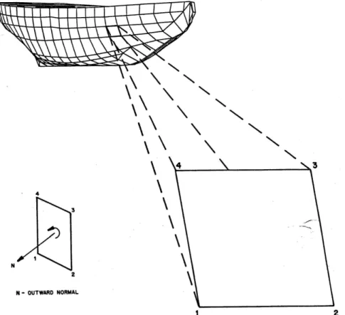
Bodies are defined by a set of nodes, which are given in global x, y, and z coordinates. These nodes are then connected to form faces and these faces, when put together, form rigid or deformable objects. Object collision detection is done for line-face and node-face interactions. For complex structures, like ship hulls, each face has to be defined separately as shown below.
Figure 1. Defining Faces for Complex Structures (Intera Technology, Inc., 1986)
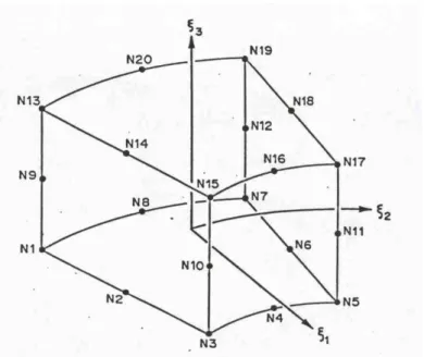
Using the MACRO-GEN card, DECICE has the ability to create many individual elements automatically, greatly facilitating the creation of simple objects. This card allows the generation of a large number of similar objects, which are subdivided as desired. Examples are shown in Figures 2 and 3 below.
3
Figure 2. Connection of Nodes for MACRO-GEN Command (Intera Technology, Inc., 1986)
2.2 DECICE Reliability
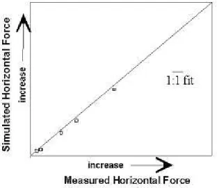
DECICE has been shown accurate by previous experiments. Below are the results of a series of ice force simulations with a 60o conical bridge pier in level ice (Lau, 1994). When compared with the results of actual model testing at the Institute for Ocean Technology, a strong correlation between calculated peak forces and the experimental results was found.
Figure 4. Level ice forces on a 60o cone: a comparison of DECICE simulations and ice tank measurements (Lau, 1994).
3.0 ICE MODEL SIMULATIONS
3.1 Ship Numerical Modeling
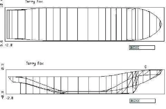
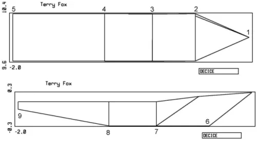
3.1.1 Terry Fox ship model
The Terry Fox is a Canadian Coast Guard icebreaker. This ship was modeled at a scale of 1:21.8. The first step in numerically modeling the Terry Fox was to reproduce its hull geometry. To do this an AutoCAD drawing of the ship was made. Points of interest were selected from this drawing so as to maximize the accuracy of the hull form and minimize the number of data points. The coordinates of these points were recorded and formed
5
The Terry Fox has a length of 88m, a width of 17.48m, a height of 12.5m, and a draft of 8.02m. One of the most important factors for accurately modeling a ship is the draft (height to the waterline).
Figure 5. Terry Fox DECICE Model
3.1.2 Simple ship model
In addition to the Terry Fox ship model, a simplified numerical ship model was also created. This was accomplished through the creation of a spreadsheet, which relies on eleven inputs and then automatically generates a model based on those parameters. The basis of this spreadsheet is that nine points can be representative of the essential points of any ship. Using these nine points combined with the offset from the global origin and the centre of gravity, this program can create a simple numerical ship model of varying size and characteristics, which can be tested and modified as needed. Utilization of this spreadsheet greatly reduces the effort necessary to produce simple ship models. Shown below is a version of a simple ship model with characteristics similar to those of the Terry Fox.
Figure 6. Simple Model of Terry Fox
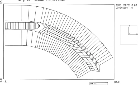
3.2 Ice Layout for Ship Simulations
In the past, the selection of points and creation of the elements for ice layouts were done manually which resulted in a very time consuming process. To facilitate their generation, these ice layouts were designed in such a manner to allow for parameters to be input that would control the creation process. The parameters to be entered include, but are not limited to:
1. ship dimensions 2. ice thickness 3. turning radius 4. ice density 5. model scale
Two possible scenarios have presently been simulated: 1. straight runs and 2. turning runs of various radii. To create ice layouts for straight runs, only 8 points are needed. Turning runs require an ice mesh configuration whose creation process is more complex. It must be ensured that all ship points are relative to an origin based at the center of the turning radius, which is perpendicular to the centre of gravity of the ship. Points are calculated along 5 different arcs to form the mesh ice. The turning radius and the ice thickness, for a given run, determine these radii. In addition to the arc ice,
7
Figure 7. Terry Fox in Mesh Ice
In determining the ice height, two things have to be accounted for: the waterline of the ship in question as well as the buoyancy of the ice. From waterline depth, the ice height is determined from solving the following 2 equations:
thickness ice l l l l l w i = + = + 2 1 2 2 1 ) (
ρ
ρ
(1)3.3 Conical Structure Modeling
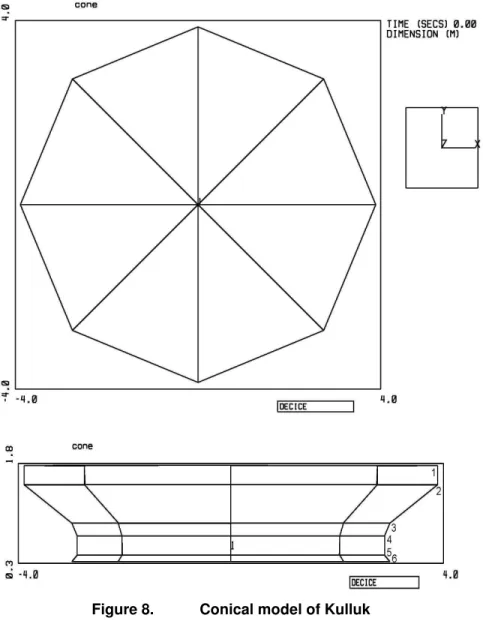
Conical structures are used in the creation of bridges like the Confederation Bridge from Prince Edward Island to the mainland. It is of interest to test conical structures
numerically to determine their reaction in situations involving ice. Conical structures are not complete cones; at varying heights the change in radius of the cone may not be constant. To facilitate the creation of conical structures, a C++ program has been created that generates the nodes for the structure as well as the inter-connection of these nodes. The user inputs 6 sets of radii and heights and the number of facets around the cone to be used, as well as the offset for the origin. With this data, an output file is created which is then copied into a data file with additional information such as material properties and physical constants. The automation of this creation process allows a large number of different conical structures to be produced and tested. An example of this type of structure is the Kulluk, the artic oil-drilling rig shown below.
Figure 8. Conical model of Kulluk 3.5 Ice Layout for Cone Simulations
Similar to the mesh ice created for ship simulations, mesh ice was also created for conical structures. This was done using a spreadsheet that takes many of the same inputs except those relating to the cone properties such as the number of faces and cone radius at waterline. The result is very similar to the ship ice, however there is no turning.
9
ice-scouring research is based on the effects of iceberg scouring, this research looked more closely at scouring caused by loosely packed ice. The keel of these ice ridges can deform, thus affecting the depth of the scouring.
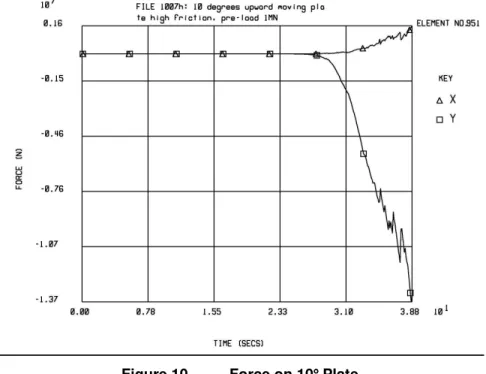
To view the forces acting upon these bodies, the DECICE simulation tool was used. A two dimensional model was created with the DECICE2D program, shown below.
Figure 9. Ice Keel Scouring of Seabed
For these simulations, a keel of width 81m, depth 13m, and a repose angle of 24 degrees was used. Inter-ice friction was varied from 0.4, 0.6 and 0.8 in various
simulations. Instead of moving the ice, a moving plate was used. The plate was 37.5m in length and the angle of inclination varied from 1 degree, 5 degrees and 10 degrees. The plated was moved at varying horizontal and vertical speeds and the forces
produced were recorded and analyzed, as shown below.
Table 1. Events up to 1MN load for 10 Plate
Event Time Fx Fy Mz Contact 24.95 0 -2.45E+03 0
1 25.25 4.00E+02 -1.19E+04 -1.15E+02 2 25.8 1.60E+03 -1.30E+04 4.80E+03 3 26.9 1.17E+04 -4.19E+04 2.12E+04 4 28.6 1.00E+04 -2.70E+05 2.75E+05 1MN 29.9 3.00E+04 -1.00E+06 3.00E+05 5 34.95 6.00E+05 -8.24E+06 -1.45E+07
11 5.0 CONCLUSION
Numerical simulation has been shown to have many advantages and a diverse range of applications. These include ship modeling, cone modeling, and ice seabed scouring simulations. The setup for many of the simulations is very tedious and time consuming. To alleviate this, some automation software was created. This has eased the use of the DECICE simulation software and made the steps toward commercialization much easier.
The DECICE tool itself has proven very versatile and usable, after sufficient training time. It has the ability to calculate forces and moments and inter-element interactions for a large variety of applications. However, in order for it to be more commercially viable, further automation is needed.
The hardware currently supporting the DECICE software is sufficient at best, but upgrades would greatly speed up all simulations and allow more of them to be run in a given time period.
Presently, there exist tools for automatically generating simple ship models, cone
models, ship ice mesh and cone ice mesh. As more of such tools are created, the value of DECICE will increase. This software holds much potential and only in time will its true abilities be shown.
6.0 RECOMMENDATIONS
The DECICE software as it stands is very capable and efficient at handling a small number of elements in a limited simulation environment. However, in order for this to become commercially viable, it must be expanded to handle larger problems. Using DECICE3D, the maximum number of elements possible for a simulation is
approximately 150 and this simply is not sufficient. Source code modification will be necessary to fix this problem.
Additionally, the code was originally written in 1986 and as such, is not optimized for today’s powerful computing hardware. Modernization of the code with a possible 64-bit implementation and associated hardware could greatly reduce the time needed to run simulations.
Furthermore, additional tools used to speed up model creation and simulation processes are needed. Tools such as these reduce the effort required to set up a simulation and are invaluable to third parties looking to purchase DECICE for similar employments.
Finally, DECICE does not refresh itself when windows are placed over the X11 viewing window. This becomes very painful if trying to look at the data and result simultaneously and will require source code modification to be fixed.
13 7.0 REFERENCES
1) Intera Technology, Inc., 1986. DECICE Theoretical Manual, Lakewood, Colorado.
2) Lau, M., 1994a. A Three Dimensional 'DECICE' Simulation of Ice Sheet
Impacting a 60-Degree Conical Structure, NRC/IMD Report CR-1994-16,
National Research Council of Canada, Institute for Marine Dynamics, St. John's, Newfoundland.