To link to this article: DOI:10.1016/j.surfcoat.2011.10.025
URL:
http://dx.doi/10.1016/j.surfcoat.2011.10.025
This is an author-deposited version published in:
http://oatao.univ-toulouse.fr/
Eprints ID: 5458
To cite this version:
Demnati, Imane and Parco, M. and Grossin, David and Fagoaga, I. and
Drouet, Christophe and Barykin, C. and Combes, Christèle and Braceras,
I. and Goncalves, S. an d Rey, Christian Hydroxyapatite coating on
titanium by a low energy plasma spraying mini-gun.
(2012) Surface and
Coatings Technology, vol. 206 . pp. 2346-2353. ISSN 0257-8972
O
pen
A
rchive
T
oulouse
A
rchive
O
uverte (
OATAO
)
OATAO is an open a ccess repository that co llects the work of To ulouse researchers
and makes it freely available over the web where possible.
Any correspondence concerning this service should be sent to the repository
administrator:
[email protected]
Hydroxyapatite coating on titanium by a low energy plasma spraying mini-gun
I. Demnati
a, M. Parco
b, D. Grossin
a,⁎
, I. Fagoaga
b, C. Drouet
a, G. Barykin
b, C. Combes
a, I. Braceras
b,c,
S. Goncalves
d, C. Rey
aaUniversité de Toulouse, CIRIMAT CNRS-INPT-UPS, ENSIACET, 4 allée Emile Monso BP 44362, 31030 Toulouse, France bINASMET-Tecnalia, Mikeletegi Pasealekua 2, Teknologi Parkea, E-20009 Donostia-San Sebastian, Spain
cCiber BBN, Spain
dTEKNIMED S.A, Z.I. Montredon, 31240 L'Union, France
a b s t r a c t
Keywords: Hydroxyapatite Plasma-spray Oxyapatite Raman spectroscopyPlasma-sprayed hydroxyapatite (HA) coatings are used on metallic implants to improve osseointegration and bone growth. The purpose of this work was to determine the microstructure and composition of HA coatings obtained with a newly developed low energy plasma spray mini-gun employing an HA feedstock powder with smaller granulometry than that commonly used.
The microstructure and the phase composition of the coatings obtained by varying the number of mini-gun runs were examined using scanning electron microscopy, X-ray diffraction and Fourier transform infrared and micro-Raman spectroscopy. In all cases, the results indicate the presence of an amorphous phase and oxyapatite in the coatings due to hydroxyl group removal. No other foreign crystalline phases were detected. The absence of foreign phases was attributed to the fast cooling rate of the small particles used in the experi-ments and the low amount of energy employed with the mini-gun.
Decomposition in the υ1PO4region of the Raman spectra allowed a semi-quantitative evaluation of the phase contents as a function of the number of runs. Micro-Raman spectroscopy appears to be a powerful technique providing comprehensive and localised information concerning calcium phosphate phases in coatings.
1. Introduction
Synthetic hydroxyapatite (HA) has been widely used as bioactive bone substitute material in the form of ceramics, cements, coatings and composites in orthopaedics and dentistry because of its excellent biocompatibility and osteoconductivity[1–6]. Nevertheless, the in-herent poor mechanical properties of HA bioceramics (brittleness, low tensile strength and poor impact resistance) have restricted their application, especially in many load-bearing applications[7]. Ti-tanium and its alloys, on the contrary, are mostly used in load-bearing applications due to their good mechanical properties and biocompati-bility. However, they suffer from certain disadvantages, such as poor osteoconductive properties. Several surface treatments of titanium-based implants have been proposed to improve their biological be-haviour[8–9]. One of the most developed surface treatments is the coating of metallic implants with HA, considered to combine the good strength and ductility of titanium with the bioactivity of calcium phosphates[10]. Hydroxyapatite has been used to coat the femoral stem of hip prostheses to promote osteointegration, and has been as-sociated with improved long-term performance[11–12].
Plasma spraying is the most industrially-developed technique for producing HA coatings onto metal implants [11–14]. The principle of plasma spraying consists of producing an ionised gas (plasma) in which hydroxyapatite powder is injected, melted and transported. A substrate located at a controlled distance from the spray gun is coated by a layer with a composition expected to be close to that of the initial powder [14–17]. However, due to the very high temperature pro-duced by the plasma flux, the initial HA powder undergoes full or par-tial melting and decomposition during plasma spraying.
The decomposition of HA can lead to various compounds such as calcium oxide and a mixture of crystalline and amorphous phases, es-pecially tricalcium phosphate (TCP) and tetracalcium phosphate (TTCP) [18]. Most plasma-sprayed HA has been reported to lose some hydroxyl groups and transform into oxyhydroxyapatite (OHA)
[19–20]. Calcium oxide in the coating is particularly harmful, since a hydration reaction which occurs during storage or after implantation in vivo transforms CaO into Ca(OH)2, with a 50% volume increase,
resulting in considerable internal strains and cracks, especially if the calcium oxide is at a high amount in the coating[21].
There is much debate in the literature regarding the ideal micro-structure, composition and morphology of HA coatings. It has been shown that the thermal decomposition of HA coatings has two oppos-ing effects: on one hand, a degradation of the coatoppos-ing and its detach-ment from the metal surface, which impairs the stability of the bone– implant interface, and on the other hand, an improvement of the
⁎ Corresponding author.
biological activity of the coating, related mainly to the existence of an amorphous phase favouring bone reconstruction[22]. Another pa-rameter that controls the coating composition and properties is the initial HA particle size. In conventional atmospheric plasma spraying systems (cAPS), the optimal mean particle size (median size diame-ter of particles d50) is greater than 100 μm with a spherical
morpholo-gy. Smaller sized powder particles can be totally melted and produce a coating rich in foreign phases[10]. In addition, if the particle size distribution is monomodal, the plasma jet is optimised and homoge-neous coatings are obtained. These particle characteristics are consid-ered to represent the best compromise for good biological activity. Nevertheless, using such coarse powders with a less energetic plasma mini-gun leads only to partial melting of particles and to coatings mainly composed of crystalline HA, but with poor cohesion and high porosity. Generally, the thickness of the HA coatings on commer-cialised medical devices ranges from 50 to 300 μm[23]. Coatings with a thickness greater than 150 μm become brittle, whereas very thin HA coatings may resorb too fast[24]. The Ca/P ratio in the coating should be very close to 1.67.
The use of cAPS to coat small implants, e.g. dental implants, pro-duces irregular non-optimal coatings, with concerns about implant failure due to microbiological susceptibility, resorption and interfacial fracture risk issues[25–26]. Furthermore, the threaded design is cur-rently dominant in the dental implant field, as cylindrical implants have shown good initial osseointegration, but unacceptably high se-condary loss of bony anchorage[27]. Obtaining thin, controlled and homogeneous coatings in these threaded geometries represents a challenge for cAPS. Therefore, there is a need to design a gun capable of coating small, geometrically complex implants with a thin, spatial-ly and compositionalspatial-ly controlled HA deposition.
This work focused on the development of a portable low energy plasma device for the deposition of hydroxyapatite coatings on small-sized implants with relatively complex geometries. The process parameters and the gun design were optimised for the deposition of HA powders. The microstructure of the coatings was characterised using scanning electron microscopy (SEM) and compositional charac-terisation was investigated using X-ray diffractometry (XRD), Fourier transform infrared spectroscopy (FTIR) and micro-Raman spectroscopy. 2. Experimental procedures
2.1. HA powder and titanium substrate
The powder particle size distribution was carefully selected to en-able a proper injection in the plasma plume and to avoid the segrega-tion of the finest particle fracsegrega-tion from the main gun axis, which may result in overheating and clogging of the particles in the nozzle. In previous industrial tests (flowability with industrial equipment), it was observed that particle clogging was difficult to avoid for powders with a particle size b50 μm.
The tested feedstock material was a hydroxyapatite powder pro-vided by Teknimed SA (L'Union, France). Briefly, after precipitation, washing and drying, the HA powder was calcined at 1000 °C for 15 hours according to international standards to achieve a completely crystalline structure[28]. Then, it was crushed, sieved and the frac-tion with particle sizes ranging between 50 and 80 μm was selected to ensure uniform melting and deposition using the spray process; the morphology of the HA particles was observed by scanning electron microscopy (SEM). They exhibited an irregular shape with sharp edges (Fig. 1).
The Ca/P molar ratio of HA powder was determined by chemical analysis and confirmed by XRD analysis of heated scraped coatings according to standard protocols [28]. Calcium was determined by atomic absorption spectrophotometry and phosphate ions were determined by spectrophotometry of a phosphovanadomolybdic complex[29–30].
The coatings were sprayed onto flat medical grade Ti grade 4 coupons (ϕ: 12 mm×3 mm) using the newly-developed low energy plasma device. Before coating, the substrate surface was degreased and grit blasted with corundum F150 using a pressure of 2 bars. 2.2. Plasma spray deposition process
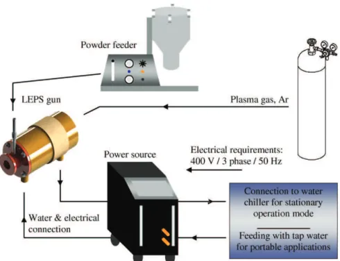
The deposition of HA was performed in air using a new Low Ener-gy Plasma Spray (LEPS) device that was developed by INASMET-TECNALIA (Spain).Fig. 2 shows a schematic representation of the system layout[31].
To reduce the safety requirements of the LEPS system, the plasma gun was designed to operate solely with argon as the plasma gas. For practical reasons, the gun is operated with standard electrodes from the F4-gun (6 mm Nozzle / Electrode/ Order No. 1018851)[31]. The entire gun is water cooled and the electric poles are separated by a glass fibre-reinforced epoxy housing. A schematic representation of the gun is shown inFig. 3. The latter is coupled with a standard DC power source (TETRIX-421WDC “SYNERGIC”, Praxair Soldadura Spain) from a TIG welding system, with a nominal maximal power of 15 kW (400 A) and electronic auto-ignition control.
The powder injector was placed in the gun nozzle specifically designed to improve heat transfer from the plasma plume to the HA powder particles and thus achieve an adequate degree of melting. The system is able to work with standard powder feeders conventio-nally used for cAPS. In this study, a commercial powder feeding unit (Twin10, Sulzer Metco, Switzerland) was employed. The vertical dis-placement of the spray gun was adjusted to 3 mm to fit the spot size of the plasma plume. The relative gun velocity was fixed at 200 mm/s. As thermal transfer to the substrate is limited by the relatively low power of the system, no cooling of the substrate was required during the coating deposition procedure.
Extensive preliminary work was conducted to optimise the spray parameters.Table 1 summarises the optimised parameters for the
Fig. 1. SEM micrographs of the HA powder (Teknimed) after sieving, with a particle size ranging between 50 and 80 μm: a) overview and b) particle surface at a higher magnification.
deposition of the investigated HA powders. The argon flow rate and the stand-off distance were optimised to increase the crystallinity of the resulting coating in combination with adequate deposition efficiency; the latter was measured in terms of the layer thickness deposited after each spray run. Several coatings were performed with thicknesses between 25 and 270 μm by varying the number of spray runs. We performed 1, 12 and 20 spray runs.
2.3. Characterisation of coatings
The microstructure of the coatings was characterised by SEM (JEOL JSM-5600LV, Japan). The physico-chemical characterisations of the coatings were performed according to ISO standards[28]and completed by FTIR and Raman spectroscopic analyses and SEM observations.
X-ray diffraction analysis was performed on the surface of coat-ings, and also on HA coatings removed from the substrate for crystal-linity ratio determinations. These measurements were performed using a Seifert XRD-3000 diffractometer (Germany) equipped with CuKα1 radiation; the goniometer was set in a step-scan mode with a rate of 0.02° for 24 seconds, over a 2θ range of 20–60°. The crystal-linity of the coatings was evaluated according to international stan-dards. The determination of coating crystallinity was based on the measurement of the integrated intensity of ten diffraction lines of the sample diagram compared to those of a fully crystallised HA refer-ence compound according to the Joint Committee on Powder Diffraction Standards (JCPDS)[28]. The Ca/P ratio of the coatings was determined by XRD analysis of heated scraped coatings according to standard proto-cols[18].
The FTIR spectra of all samples were obtained in the range of 4000–400 cm− 1for removed and ground coatings. They were performed
in accordance with ISO standards[28]using a Fourier-transform infrared spectrometer (Nicolet 5700, France), both by attenuated total reflec-tance (ATR) using a diamond ATR device (4 cm− 1resolution) on the Fig. 2. Schematic representation of the low-energy plasma spray system.
Fig. 3. Schematic representation of the newly-developed low-energy plasma gun: 1) water inlet and electrical connection, 2) water outlet and electrical connection, 3) powder injector, 4) plasma gas inlet and 5) insulated housing.
Table 1
Process parameters.
Argon (L/min) 24
Current (A) 400
Carrier gas (Ar, L/min) 4
Powder feeding rate (g/min) 8
Stand-off distance (mm) 40
coating surfaces and by transmission using KBr pellets (4 cm− 1
resolu-tion) on the scraped coatings.
Raman spectra of the coating surfaces were recorded using a Horiba Jobin-Yvon HR 800 spectrometer (France) equipped with a helium-neon laser (λ=632.8 nm) in the range of 100–1200 cm− 1 and
3500–3650 cm− 1. A semi-quantitative evaluation of different
compo-nents of the ν1PO4band was performed using GRAMS/32 curve-fitting
software. All the Raman spectra were decomposed according to a pub-lished protocol in order to facilitate their comparison[32]. A baseline correction was performed on each spectrum. Peak positions and some curve parameters were recorded and used as initial input in the curve-fitting program. Iterations continued until the best fit (i.e. conver-gence) was obtained.
3. Results
3.1. Microstructural characterisation
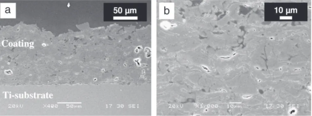
Fig. 4shows SEM micrographs of a cross-section of HA coating produced with 12 spray runs. The coating shows a typical lamellar structure. Some isolated volume defects (large pores) were produced during spraying, but no cracks were observed in the cross-section of the coatings. For the most part, the porosity consisted of small inter-lamellar voids. The microstructure of the coating was mainly com-posed of flattened particles over a small amount of partially melted particles (Fig. 5).
3.2. Compositional characterisation
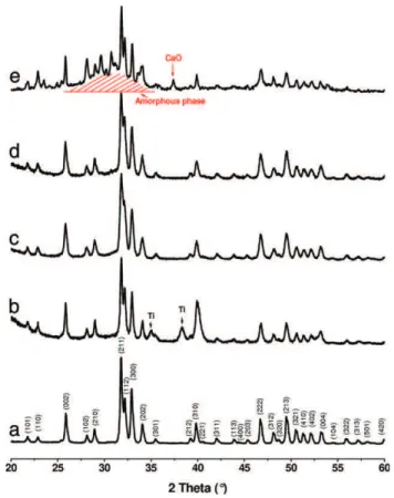
The X-ray patterns of as-sprayed HA coatings compared to HA pow-der are shown inFig. 6. All the peaks of the HA powder corresponded to a well-crystallised single phase of Ca10(PO4)6(OH)2(JCPDS 09-432); no
foreign crystallised phase was detected.
For the coating produced with one spray run, two additional peaks (2θ =34.98° and 38.30°) corresponding to the titanium substrate were detected (Fig. 6b), due to the thinness of the coating. In parti-cular, the characteristic peaks of CaO, α- and β-TCP and TTCP were absent. The amorphous phase produced a barely visible broad peak of very low intensity centred around 2θ= 30.50°. On the contrary, some HA coatings made with the same feedstock powder but using the cAPS system provided decomposed coatings (Fig. 6e).
The crystallinity ratio of 12-run coatings calculated according to the international ISO standard[28]was 68% compared to the HA feed-stock[33].
The FTIR spectra of the initial HA powder and of the coatings are shown in Fig. 7. The bands related to phosphate and OH−groups
appeared broader and less resolved in the coatings compared to the initial powders. The main phosphate bands (ν3PO4 and ν4PO4) at
1000–1100 cm− 1and 560–600 cm− 1of the coating spectrum (Fig. 7,
spectra b, c and d) showed less resolution than those observed for the initial HA powder spectrum (Fig. 7, spectrum a). The relative intensity
of the ν2PO4bands at 434 and 471 cm− 1appeared much stronger in
the coating than in the initial powder. In addition, a clear decrease of the intensity of the OH−stretching band at 3570 cm− 1and of the
OH−vibration band at 633 cm− 1was also observed for the spectra of
the coatings compared with that of the initial HA powder.
The Raman spectra of the samples are presented inFig. 8. For all samples, two distinct peaks appeared at about 430 and 452 cm− 1in
the region of the ν2PO4bending mode. In the region of the ν4PO4
bending mode, four distinguishable peaks appeared at 580, 594, 609 and 620 cm− 1. The ν
3domain of the phosphate groups stretching
mode was the same for the feedstock HA powder and HA coatings; three peaks were distinguished at 1027, 1048 and 1075 cm− 1.
On the contrary, the ν1PO4 domain appeared to be the most
affected by the use of the low energy plasma spray process. For the HA powder, a single thin band at about 962 cm− 1was observed.
However, several specific bands in all HA coatings could be distin-guished at 966–969, 950–951, 961–963, and 945–950 cm− 1. The
broad band at 945–954 cm− 1could be attributed to the amorphous
phase[32,35]. The bands at 950–951 and 966–969 cm− 1have been
assigned to oxyapatite[32,34]. The band at 961–963 cm− 1
corres-ponded to the PO4groups in the remaining HA phase, which always
appeared as one of the most intense bands. The curve fitting shown inFig. 9and peak positions reported inTable 2indicate the contribu-tion of these species to the ν1PO4band. Despite the observation that
the proportion of oxyapatite lines increased and that the contribution of the amorphous phase decreased as a function of the number of runs, it seems, however, difficult at this stage to go further and give an estimated composition of the coating.
4. Discussion
The main problems associated with the plasma spray processing of HA are the control of the resulting coating microstructure and com-position and the coating of relatively complex geometries. The de-composition of HA is difficult to limit in conventional plasma spray systems (Table 3).
The high temperatures of the plasma induce a loss of hydroxide ions in HA particles at temperatures higher than 1000 °C. The HA may undergo a partial dehydroxylation to oxyhydroxyapatite (OHA) following the reaction below:
Ca10ðPO4Þ6ðOHÞ2X Ca10ðPO4Þ6ðOHÞ2−2xOx□xþ xH2O ð1Þ
According to the CaO–P2O5–H2O diagram[36], the OHA starts to
decompose above 1300 °C to give a mixture of tricalcium phosphate and tetracalcium phosphate according to the following reaction: Ca10ðPO4Þ6ðOHÞ2−2xOx□xX 2Ca3ðPO4Þ2þ Ca4O POð 4Þ2þ 1−xð ÞH2O ð2Þ
Above 1640 °C, calcium oxide and a liquid phase are formed. All these reactions are completely reversible on cooling.
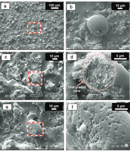
It is generally admitted that HA particles are partially or totally melted in the plasma[38]. They tend to be spheroidised during the deposition process and they splatter onto and attach to the material already deposited, giving the characteristic lamellar microstructure of the coating observed on the micrographs (Fig. 4). The un-melted core can be broken into pieces forming a fine-graded zone sometimes observed at the surface (Fig. 5). With rapid cooling, part of the liquid solidifies as an amorphous phase with crystalline impurities (α and β-TCP and TTCP) related to the re-crystallisation of the high tempera-ture phases, and as oxy-hydroxyapatite with a smaller crystallite size than the initial HA.
Table 3summarises the composition of some reference cAPS coat-ings reported in the literature in comparison to the developed LEPS HA coating. In addition to crystalline HA, cAPS-coatings usually con-tain TCP (α and β forms), TTCP and CaO and an amorphous calcium phosphate mixture. The physico-chemical events occurring in the LEPS system can be considered as similar to those of cAPS. The main dif-ferences correspond to the quantity of amorphous calcium phosphate (ACP), which is very low using the LEPS system, and the absence of a de-tectable foreign crystalline phase.
The number of spray runs influenced the coating crystallinity and its composition. Coatings produced with one run, for example (Fig. 9a), showed the presence of a higher amount of the amorphous phase
than coatings with multiple runs. This presence was usually attributed to the rapid quenching rate resulting from the elevated thermal gra-dient between the melted HA particles and the titanium substrate, which has a large thermal conductivity and quenching capability. The ratio of oxyapatite (measured on the top surface) seemed to increase with the number of runs, whereas the amount of amorphous phase decreased (Fig. 9b and c). This may also be related to variations in the cooling rate when the first layer of HA is deposited. The thermal con-ductivity of HA is much lower than that of the titanium substrate and a partial re-crystallisation into oxy-hydroxyapatite of the amorphous phase may occur[22,37–39]. After 12 spray runs, the resulting coating seemed to have an optimal thickness of around 150 μm, and a higher crystalline HA ratio.
The absence of measurable foreign crystalline phases in coatings produced by the LEPS system was rather puzzling. Almost all previous studies on cAPS HA coatings have reported the presence of phases resulting from the thermal decomposition of HA, although the amount of these impurities is strongly related to the conditions of deposition. In LEPS coatings, an amorphous phase indicative of mel-ting of the HA particles at a temperature higher than 1600 °C is ob-served, also associated with the formation of oxy-hydroxyapatite corresponding to de-hydroxylation of the HA phase in the domain of 1000–1300 °C. However, the phases originating from the decomposition
Fig. 5. SEM micrographs of HA coatings obtained after one run of the plasma mini-gun: a) c) and e) show recrystallised regions and partially melted regions (dotted square); b), d) and f) show micrographs of the dotted squares at a higher magnifications. SEM micrographs of HA coatings obtained after 1-run of the plasma mini-gun showing:(a) a re-solidified particle with a melted region (dotted square: (b)); (c) and (e) represent two recrystallised regions and a partially melted region (dotted square: (d) and (f)).
of oxy-hydroxyapatite in the domain of 1300–1600 °C do not appear to crystallise. Although the reactions occurring during the plasma spray process are far from the equilibrium conditions of the phase diagram, the observation of these phases in most cAPS coatings justifies the refe-rence to these diagrams. It has been suggested that when the cooling rate is sufficiently high, the short-range diffusion necessary for the for-mation of tricalcium phosphates and tetracalcium phosphate cannot
occur[22,40]. The cooling rate is difficult to evaluate; nevertheless, it can be hypothesised that it is faster in LEPS than in cAPS due to the smal-ler size of the sprayed particles, the shortened residence time in the plas-ma and the lower energy provided by the LEPS system. This explanation does not appear, however, to be totally convincing as there is evidence for the re-formation of oxy-/hydroxyapatite from the melt; it might be observed that this re-formation could be equally avoided by short range diffusion in the rapidly cooling liquid. An alternative explana-tion could be related to undercooling and the existence or not of crystal nuclei. In the LEPS system, the small particle size and low energy in-volved allow a fast cooling rate, and the absence of α- and β-TCP and TTCP nuclei in the particles may prevent the crystallisation of these
Fig. 6. XRD diagrams of hydroxyapatite: (a) initial powder and coatings with 1 (b), 12 (c) and 20 runs (d) of the plasma LEPS gun. (Ti: titanium substrate) (e). Decomposed coating made with the same feedstock powder but by cAPS.
Fig. 7. FTIR spectra of HA powders (a) and HA coating: 1 run (b), 12 runs (c) and 20 runs (d) of the plasma LEPS-gun.
Fig. 8. Raman spectra of HA powder (a) and HA coating with 1 (b), 12 (c) and 20 (d) runs of the plasma LEPS gun.
phases and possibly keep the melt undercooled for a short period of time in the range of 1300–1600 °C. However, the unmelted apatite cores in the particles provide a nucleation surface for apatite crystals from the undercooled melt. Even though the liquid would be under-cooled for a very short period of time in the range of 1300–1600 °C, its crystallisation into apatite could be facilitated by the remaining apatite crystals (at least in the vicinity of these crystals) before solidification of the liquid phase as an amorphous glass. The hypothesis of undercooling in the presence of apatite nuclei could thus explain the re-formation of oxy-hydroxyapatite crystals at the expense of the amorphous phase, whereas the absence of nuclei could explain why the formation of the foreign crystalline phase did not occur, although this is predicted by the phase diagram. In the cAPS systems, the cooling rate should be lower due to the larger particle size and higher energy transfer involved in this process. The unstable undercooled liquid could then have enough time to crystallise, in the range 1600–1300 °C, into α-TCP and TTCP. β-TCP could even be observed if the quenching rate is not fast enough to prevent the phase transition.
Although not recommended by the standards regulating HA plasma-sprayed coating, micro-Raman spectroscopy provides reliable and useful information for studying the chemical composition of plasma-sprayed HA coatings This technique allows a fine distinction between oxy- and hydroxyapatite and permits distinguishing the amorphous phase from HA, even at a low content[32,34], in contrast to XRD.
In the future, further studies will focus on the chemical gradient across the thickness of the coating using micro-Raman spectroscopy. Low energy plasma spray presents several conceptual advantages over conventional plasma spraying: the smaller diameter of the plas-ma plume and shorter stand-off distance (SOD=40 mm) allows for more precise coating deposition, simplicity and less energy consump-tion. In addition, it was found to improve the crystallinity and purity of the HA coating.
5. Conclusions
A low energy plasma device was developed for HA coatings on small-sized implants. Maintenance costs and needs can potentially be reduced in comparison to conventional plasma spray systems, and the lower technical requirements in terms of power supply, water cooling rate and exhaust might allow for the implementation of this system in portable applications. The results demonstrated that even at only 15 kW of power and using argon as the plasma gas, the system is able to produce higher crystalline HA coatings than those observed with conventional plasma systems. The amor-phous phase represents a low fraction of the coating, and no foreign phases are produced in measurable amounts.
The low energy plasma spray process could thus represent pro-gress, especially for coating small-sized implants, for which conven-tional plasma spraying appears to be inappropriate.
Other studies in progress are related to the spraying of new apati-tic powder compositions and the in vivo evaluation of the coatings.
Acknowledgments
This study was carried out under an MNT ERA-Net Project called NANOMED. The authors gratefully thank the Midi-Pyrénées region for financial support for research carried out in the CIRIMAT Laboratory (France), and the Basque government and Tratamientos Superficiales Iontech, S.A. for their financial and technical support under the IG-2007/0000381 grant for the development of the LEPS device and depo-sition of the coatings carried out at INASMET-Tecnalia. Industrial French collaborators (TEKNIMED SA and 2PS SA) were financed by OSEO programs.
Fig. 9. Gaussian–Lorentzian curve-fitting of the ν1PO4Raman stretching domain of an HA
coating: 1 run (a) 12 runs (b) and 20 runs (c) of the plasma LEPS gun): Peak 1: Amor-phous calcium phosphate (ACP), Peaks 2 and 4: Oxyapatite and Peak 3: Hydroxyapatite.
References
[1] C. Drouet, F. Bosc, M. Banu, C. Largeot, C. Combes, G. Dechambre, C. Estournès, G. Raimbeaux, C. Rey, Powder Technology 190 (2009) 118.
[2] D. Eichert, C. Drouet, H. Sfihi, C. Rey, C. Combes, Biomaterials Research Advances (2008) 93.
[3] L.L. Hench, J. Am. Ceram. Soc. 81 (1998) 1705.
[4] T. Kasuga, M. Nogami, M. Niinomi, Adv. Eng. Mater. 5 (2003) 498.
[5] S.-H. Kwon, Y.-K. Jun, S.-H. Hong, I.-S. Lee, H.-E. Kim, Y.Y. Won, J. Am. Ceram. Soc. 85 (2002) 3129.
[6] W. Xue, J.L. Moore, H.L. Hosick, S. Bose, A. Bandyopadhyay, W.W. Lu, K.M.C. Cheung, K.D.K. Luk, J. Biomed. Mater. Res. A 79A (2006) 804.
[7] M. Jarcho, Clin. Orthop. Relat. Res. 157 (1981) 259. [8] A. Perry, Surf. Eng. 3 (1987) 154.
[9] J. Breme, Mém Études Sci. Rev. Métal. 86 (1989) 625. [10] J.E. Lemons, Clin. Orthop. Relat. Res. 235 (1988) 220. [11] L. Sun, C.C. Berndt, C.P. Grey, Mater. Sci. Eng. A 360 (2003) 70.
[12] L. Erickson, R. Westergård, U. Wiklund, N. Axen, H. Hawthorne, S. Hogmark, Wear 214 (1998) 30.
[13] V. Deram, C. Minichiello, R.N. Vannier, A. Le Maguer, L. Pawlowski, D. Murano, Surf. Coat.Technol. 166 (2003) 153.
[14] K. De Groot, R. Geesink, C. Klein, P. Serekian, J. Biomed. Mater. Res. 21 (1987) 1375. [15] P. Habibovic, F. Barrère, K. De Groot, Learning from Nature How to Design New Implantable Biomaterialsis: From Biomineralization Fundamentals to Biomimetic Materials and Processing Routes, 2005, p. 105.
[16] Y. Liu, K. De Groot, E. Hunziker, Front. Mater. Sci. Chfsina 3 (2009) 154.
[17] F. Barrère, C. Van der Valk, G. Meijer, R. Dalmeijer, K. De Groot, P. Layrolle, J. Biomed. Mater. Res. 67 (2003) 655.
[18] M. Carayon, J. Lacout, J. Solid State Chem. 172 (2003) 339.
[19] R. McPherson, N. Gane, T. Bastow, J. Mater. Sci. Mater. Med. 6 (1995) 327. [20] J. Knowles, K.A. Gross, C. Berndt, W. Bonfield, Biomaterials 17 (1996) 639. [21] K.A. Gross, C.C. Berndt, J. Biomed. Mater. Res. 39 (1998) 580.
[22] K.A. Gross, C. Berndt, H. Herman, J. Biomed. Mater. Res. A 39 (1998) 407. [23] L. Sun, C.C. Berndt, K.A. Gross, A. Kucuk, J. Biomed. Mater. Res. 58 (2001) 570. [24] R.B. Heimann, Surf. Coat.Technol. 201 (2006) 2012.
[25] H. Kido, S. Saha, J. Long Term Eff. Med. Implants 6 (1996) 119. [26] J. Ong, D. Chan, Crit. Rev. Biomed. Eng. 28 (2000) 667.
[27] T. Albrektsson, L. Sennerby, A. Wennerberg, Periodontol. 2000 2008 (47) (2008) 15. [28] ISO 13779–3:2008, Implants for surgery-Hydroxyapatite-Chemical analysis and
characterization of crystallinity and phase purity. [29] A. Gee, V. Deitz, Anal. Chem. 25 (1953) 1320.
[30] G. Charlot, Chimie analytique quantitative, Masson, Paris, 1974. [31] G. Barykin, in, WO Patent WO/2008/000,851, 2008.
[32] X. Ranz, (1996).
[33] C. Yang, B. Wang, E. Chang, J. Wu, J. Mater. Sci. Mater. Med. 6 (1995) 249. [34] J. Trombe, G. Montel, C.R. Acad. Sci. Paris Ser. C 276 (1973) 1271. [35] G. Penel, G. Leroy, C. Rey, E. Bres, Calcif. Tissue Int. 63 (1998) 475. [36] P. Riboud, Ann. Chim. 8 (1973) 381.
[37] P. Cheang, K. Khor, Biomaterials 17 (1996) 537.
[38] J. Chen, J.G.C. Wolke, K. de Groot, Biomaterials 15 (1994) 396. [39] C. Chang, J. Huang, J. Xia, C. Ding, Ceram. Int. 25 (1999) 479.
[40] K. Gross, C. Berndt, P. Stephens, R. Dinnebier, J. Mater. Sci. 33 (1998) 3985. Table 2 Curve-fitting data. Peak 1 ACP Peak 2 Oxyapatite Peak 3 Hydroxyapatite Peak 4 Oxyapatite Reduced χ2
1 run; HA coating 949.8 ± 0.1 950.11 ± 0.03 962.44 ±0.04 968.48 ±0.09 7.47E-12
12 runs; HA coating 953.4 ± 0.4 950.11 ± 0.06 963.24 ±0.01 969.39 ±0.04 3.43E-14
20 runs; HA coating 950.0 ± 0.5 950.43 ± 0.02 963.04 ±0.01 969.93 ±0.01 0.80E-14
Table 3
Composition of HA coating obtained by conventional plasma spraying according to the literature and compared with our results.
Authors and references Power level (kW) Non-apatitic crystalline phases Characterisation techniques
Deram et al.[13] – TTCP SEM, XRD, WDSa
Gross and Berndt[21] 18; 24 TCP DTA/TGA, XRD, X-ray fluorescence, SEM
Gross and Berndt[21] 30; 36 CaO, TCP, TTCP DTA/TGA, XRD, X-ray fluorescence, SEM
Heimann et al.[33] 26; 30; 34 TCP, TTCP XRD, Rietveld refinement, LRSb
Cheang and Khor[34] 40 CaO, TCP, TTCP XRD, SEM
LEPS coatings (this work)
15 – XRD, FTIR, RAMAN, SEM
aWDS: wavelength dispersion spectrometer. b LRS: Laser-Raman Spectroscopy.