Département de génie civil
FLEXURAL STRENGTH AND SERVICEABILITY OF
CIRCULAR CONCRETE MEMBERS REINFORCED
WITH FRP BARS AND SPIRALS
Étude de la résistance en flexion et du comportement en service d'éléments
circulaires en béton armé de barres et de spirales de PRF
Thèse de doctorat Spécialité: génie civil
Salaheldin Abdallah Ali Abdelhamed MOUSA
A dissertation submitted in partial fulfillment of the requirements for the degree of
Doctor of Philosophy (Civil Engineering)
Sherbrooke (Québec) Canada July 2018
Prof. Brahim BENMOKRANE Supervisor
Prof. Ehab EL-SALAKAWY Examiner
Prof. Adel ELSAFTY Examiner
Prof. Sébastien LANGLOIS Examiner
DEDICATION
To the memory of my father
To my mother
To my wife and my daughters
To my sister and my brother
i
ABSTRACT
Circular reinforced concrete (RC) members are widely used in infrastructure systems, such as bridge piers and piles, contiguous pile walls, and fender piles in marine structures. This is due to the simplicity of construction and because their strength characteristics under lateral loads are similar in all directions. Such members are usually exposed to aggressive environments that corrode the steel reinforcement. The result is structure deterioration, leading to costly repairs and rehabilitation. The use of fiber-reinforced polymer (FRP) as alternative reinforcing bars in RC structures has emerged as an alternative solution to overcoming the corrosion problem. In this research study, an experimental program was designed to investigate the flexural behavior and serviceability of concrete members with circular section and reinforced with FRP bars and spirals. A total of nine large-scale specimens with a total length of 6,000 mm and 500 mm in diameter were constructed and tested under four-point bending. The test parameters included the longitudinal-reinforcement ratio and the longitudinal-reinforcement type, including glass FRP (GFRP), carbon FRP (CFRP), basalt FRP (BFRP), and steel bars. The experimental results are reported in terms of moment–deflection behavior, flexural capacity, mode of failure, crack patterns, crack spacing, and crack widths. An analytical strain-compatibility model capable of predicting the flexural strength of circular FRP-RC members, including the sequential progressive failure, was developed and verified with the experimental results. Moreover, a simplified method, including design equations and design chart is presented using non-iterative analysis. This method accurately and simply predicted the flexural capacity and can be considered a simple and more straightforward for practicing engineers. In addition, the developed finite element model predicted the response of tested specimens with a reasonable degree of accuracy and was used to extend the range of investigated parameters. Crack-control models in the current FRP codes and design guidelines are reexamined, extended, and applied to circular FRP-RC members. The comparison with the experimental results indicates that the crack-control formulae developed from rectangular FRP-RC members are intended to allow for the cracking control of circular FRP-RC members by using the redefined parameters developed and proposed in this study. Finally, the measured deflections and experimental values of the effective moment of inertia (Ie) were analyzed and compared with those predicted using
available models. The ACI 440.1R-15 model is found to overestimate the effective moment of inertia at service load level, and an appropriate modification is presented based on the results of the tested circular specimens. Moreover, an analytical model has been developed by using a layer-by-layer approach to predict the load-deflection relationship of circular FRP-RC members. The model predictions were in a good agreement with the experimental results. Keywords: concrete; FRP bars; circular members; piles; flexural strength; serviceability; sectional analysis; finite element analysis.
ii
Les éléments circulaires en béton armé (BA) sont largement utilisés dans les structures comme les piliers et pieux de ponts, les parois berlinoises et les colonnes de soutien pour les structures marines. L’utilisation bien répandue de ce type d’éléments est principalement due à leur simplicité de mise en place, leur résistance caractéristique et la résistance similaire en flexion dans toutes les directions. Ces éléments sont souvent exposés à des environnements agressifs, ce qui accélère la corrosion des barres en acier. Il en résulte des structures qui se détériorent plus rapidement menant à des coûts importants de réparation et de réhabilitation. L’utilisation des polymères renforcés de fibres (PRF) est une alternative intéressante de renforcement des structures en BA afin de contrer les problèmes liés à la corrosion de l’armature. Dans cette étude, un programme expérimental a été conçu pour étudier le comportement en flexion, à l’ultime et en service, des éléments en béton ayant une section circulaire et renforcés avec des barres et des spirales en PRF. Pour ce faire, neuf spécimens de grande taille, soit d'une longueur totale de 6 000 mm et d'un diamètre de 500 mm, ont été construits et testés en flexion en quatre points. Les paramètres d'essai comprenaient le ratio et le type de renforcement longitudinal, y compris le PRF de verre (PRFV), le PRF de carbone (PRFC), le PRF de basalte (PRFB) et les barres d'acier. Les résultats expérimentaux comprennent le comportement moment-déformation, la résistance en flexion, le mode de rupture, le patron de fissuration, l’espacement des fissures et la largeur des fissures. Un modèle analytique basé sur la compatibilité des déformations, capable de prédire la résistance en flexion des éléments circulaires en BA-PRF et incluant le mode de rupture progressif, a été développé et validé avec les résultats expérimentaux. De plus, une méthode simplifiée, non itérative, comprenant des équations et un graphique pour la conception est présentée. Cette méthode prédit précisément et simplement la capacité en flexion et est considérée comme une méthode suffisamment simple pour être utilisée par les ingénieurs de la pratique. En outre, le modèle développé par éléments finis a prédit la réponse des échantillons testés avec un degré de précision raisonnable et a été utilisé pour étendre la gamme des paramètres étudiés. Les modèles de contrôle de fissure dans les codes sur PRF et les directives actuelles de conception sont réexaminés, étendus et appliqués aux éléments circulaires de BA-PRF. La comparaison avec les résultats expérimentaux indique que les équations permettant de limiter la fissuration, développées à partir des éléments rectangulaires en BA-PRF, peuvent être utilisées pour contrôler la fissuration des éléments circulaires en BA-PRF en utilisant les paramètres redéfinis proposés dans cette étude. Finalement, les déplacements mesurés et les
valeurs expérimentales du moment d'inertie effectif (Ie) ont été analysés et comparés aux valeurs
prédites en utilisant les modèles disponibles dans les normes. Le modèle de l’ACI 440.1R-15 surestime le moment d'inertie effectif au niveau de la charge de service. Afin de pallier cet écart, une modification est présentée sur la base des résultats des essais sur les éléments circulaires. De plus, un modèle analytique a été développé en utilisant une approche couche par couche pour
iii
prédire la relation charge-déformation des éléments circulaires en BA-PRF. Finalement, les prédictions effectuées par ce modèle sont en accord avec les résultats expérimentaux.
Mots-clés: béton; barres en PRF; éléments circulaires; piles; résistance en flexion; service; analyse sectionnelle; analyse par éléments finis.
iv
First of all, thanks to God for his grace and mercy, and for giving me the effort to complete this work.
I am fortunate enough to carry out this work under the supervision of Prof. Brahim
Benmokrane. It was a great honor to work with a great professor like him. He sincerely
supported me throughout this work and offered any possible help to overcome every difficulty I faced.
Words will never be able to express my deepest gratitude and appreciation to Dr. Hamdy
Mohamed, for his kindness, great patience, continuous support and unlimited help throughout
the work.
Many thanks to Profs. Ehab El-salakawy, Adel Elsafty, and Sébastien Langlois for accepting to be jury members of this dissertation and giving time to read and review.
The author would like to express his special thanks and gratitude to the Natural Science and Engineering Research Council of Canada (NSERC), Canada Research Chair Program, the Fonds de la recherche du Quebec–Nature et Technologie – (FRQ-NT) for their financial support, and Pultrall Inc. (Thetford Mines, QC, Canada) for the donation of the FRP materials.
The author thanks the technical staff of the CFI structural laboratory in the Department of Civil Engineering at the University of Sherbrooke. The author is grateful to Marc Demers and Jérôme Lacroix for their valuable contributions to testing.
Many thanks also go to my colleagues and friends at the University of Sherbrooke for their invaluable help during the experimental program.
Last but not least, I would like to convey my love to my mother, my wife, my daughters, my
v
TABLE OF CONTENTS
ABSTRACT ... i RÉSUMÉ ... ii ACKNOWLEDGEMENT ... iv TABLE OF CONTENTS ... vLIST OF FIGURES ... xiii
LIST OF TABLES ... xix
CHAPTER 1. INTRODUCTION ... 1 1.1. General ... 1 1.2. Research significance... 4 1.3. Research objectives ... 4 1.4. Research methodology ... 5 1.5. Dissertation Layout ... 6
CHAPTER 2. LITERATURE REVIEW ... 9
2.1. General ... 9 2.2. FRP Materials ... 9 2.2.1. FRP Constituent materials ... 9 2.2.1.1. Fibers ... 9 2.2.1.2. Resins ... 10 2.2.2. Manufacturing process ... 10
2.2.3. FRP products as internal reinforcement ... 11
2.3. Flexural behavior and strength of rectangular FRP-RC members ... 11
2.3.1. Flexural capacity of rectangular FRP-RC members ... 11
2.3.2. Parameters affecting moment capacity of FRP-RC members ... 15
2.3.2.1. Effect of reinforcement ratio ... 15
2.3.2.2. Effect of concrete strength ... 16
2.3.2.3. Effect of FRP reinforcement surface ... 16
2.4. Ductility and deformability ... 16
2.4.1. Energy-Based Ductility Index ... 17
2.4.3. Curvature-Based Deformability Index ... 18
2.5. Serviceability performance of rectangular FRP-RC members ... 18
2.5.1. Crack control of FRP-RC members ... 18
2.5.2. Deflection of FRP-RC members ... 21
2.6. Cracking and Deflection code provisions for FRP-RC members ... 27
2.6.1. Canadian Standards Association CAN/CSA S806-12 ... 27
2.6.1.1. Cracking ... 27
2.6.1.2. Deflection ... 28
2.6.2. Canadian Standards Association CAN/CSA S6-14 ... 28
2.6.2.1. Cracking ... 28
2.6.3. American Concrete Institute ACI440.1R-15 ... 28
2.6.3.1. Cracking ... 29
2.6.3.2. Deflection ... 29
2.6.4. Japan Society of Civil Engineers JSCE-97 ... 30
2.6.4.1. Cracking ... 30
2.6.5. Italian National Research Council CNR-DT 203/2006 ... 30
2.6.5.1. Cracking ... 31
2.6.5.2. Deflection ... 32
CHAPTER 3. FLEXURAL STRENGTH AND DESIGN ANALYSIS OF CIRCULAR RC MEMBERS WITH GFRP BARS AND SPIRALS ... 33
3.1. Introduction ... 35
3.2. Research Significance ... 36
3.3. Experimental Program ... 36
3.3.1. Materials ... 36
3.3.2. Test Specimens ... 37
3.3.3. Instrumentation and Test Setup ... 40
3.4. Test Results and Discussion ... 41
3.4.1. Moment–Deflection Behavior ... 41
3.4.2. Effect of Modulus of Elasticity and Axial Stiffness of Flexural Reinforcement 42 3.4.3. Effect of GFRP Reinforcement Ratio ... 43
vii
3.4.5. GFRP Flexural-Strain Behavior ... 45
3.4.6. Concrete Strain ... 47
3.4.7. Neutral-Axis Depth ... 48
3.5. Ductility and Deformability ... 48
3.5.1. Absorbed-Energy Approach ... 49
3.5.2. Deformability Approach ... 49
3.6. Theoretical Study ... 50
3.6.1. Stage 1: Analysis of the First Peak Moment ... 51
3.6.2. Stage 2: Analysis of the Second Peak Moment ... 53
3.6.3. Comparison between the Theoretical and Experimental Results ... 55
3.6.4. Proposed Simplified Method for Designing Circular GFRP-RC Members ... 56
3.7. Conclusions ... 59
CHAPTER 4. STRENGTH AND DEFORMABILITY ASPECTS OF CIRCULAR CONCRETE MEMBERS REINFORCED WITH HYBRID CARBON-/GLASS-FRP REINFORCEMENT UNDER FLEXURE ... 61
4.1. Introduction ... 63
4.2. Research on Circular Concrete Members reinforced with CFRP ... 64
4.3. Objectives ... 65
4.4. Experimental Program ... 65
4.4.1. Material Properties ... 65
4.4.1.1. CFRP Bars and GFRP Spirals ... 65
4.4.1.2. Steel Reinforcement ... 66
4.4.1.3. Concrete ... 66
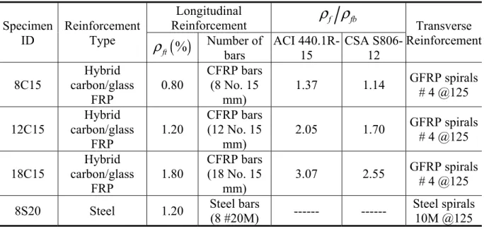
4.4.2. Specimen Details and Test Matrix ... 67
4.4.3. Specimen Design ... 69
4.4.4. Instrumentation and Test Setup ... 71
4.5. Test Results and Discussion ... 72
4.5.1. General Behavior and Failure Modes ... 72
4.5.2. Effect of Test Parameters ... 76
4.5.2.1. Effect of the Axial Stiffness of Longitudinal Reinforcement ... 76
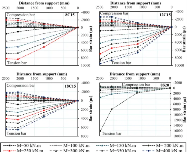
4.5.3. Bar-Strain Distribution along the Span ... 78
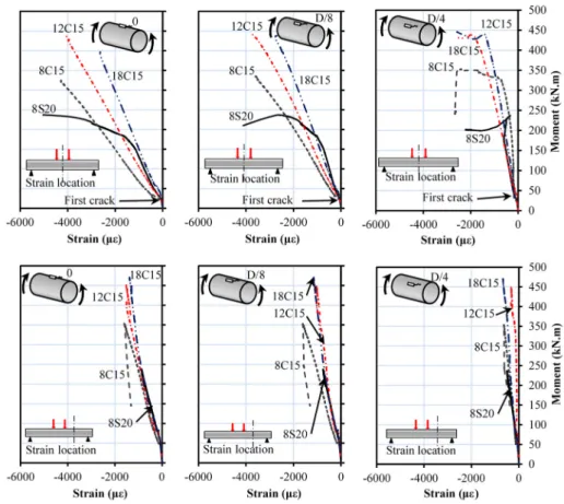
4.5.4. Strain Distribution over the Cross Section ... 80
4.5.5. Efficiency of GFRP Spirals ... 81
4.6. Ductility and Deformability ... 82
4.6.1. Energy-Based Ductility Index ... 82
4.6.2. Deformability Factor ... 83
4.6.3. Curvature-Based Deformability Index ... 84
4.7. Analytical Model ... 84
4.7.1. Proposed Computer Program ... 85
4.7.1.1. Solution Procedure ... 85
4.7.1.2. Comparison between the Theoretical and Experimental Results ... 88
4.7.2. Simple Model for Flexural Strength ... 89
4.8. Conclusions ... 92
CHAPTER 5. FLEXURAL BEHAVIOR OF FULL-SCALE CIRCULAR CONCRETE MEMBERS REINFORCED WITH BASALT FRP BARS AND SPIRALS: TESTS AND THEORETICAL STUDIES ... 95
5.1. Introduction ... 97
5.2. Research on Concrete Members Reinforced with BFRP Bars ... 98
5.2.1. Research Objectives ... 100
5.3. Experimental Program ... 101
5.3.1. Test Matrix and Parameters ... 101
5.3.2. Material Properties ... 103
5.3.3. Test-Specimen Fabrication ... 103
5.3.4. Test Setup and Instrumentation ... 105
5.4. Test Results and Observations ... 106
5.4.1. Failure Modes and Cracking Pattern ... 106
5.4.2. Flexural Behavior of the Specimens ... 109
5.4.3. Strains in Concrete ... 112
5.4.4. Strains in Longitudinal and Transverse Reinforcement ... 113
5.4.5. Variation in Neutral-Axis Depth ... 115
ix
5.5.1. Influence of Longitudinal-Reinforcement Type ... 116
5.5.2. Influence of the Reinforcement Ratio ... 116
5.6. Analytical Model ... 117
5.6.1. Materials Relationships ... 117
5.6.2. Model Description ... 118
5.6.3. Comparison of the Analytical and Experimental Results ... 120
5.7. Non-Iterative Analysis Method for Calculating Nominal Flexural Strength ... 121
5.8. Finite-Element Model ... 124
5.8.1. Element-Type Descriptions ... 124
5.8.2. Material Modeling ... 125
5.8.3. Geometry, Loading, and Boundary Conditions ... 125
5.8.4. Model Verification ... 127
5.8.5. Parametric Study ... 128
5.8.5.1. Effect of Concrete Strength ... 128
5.8.5.2. Effect of the Longitudinal-Reinforcement Ratio ... 129
5.9. Conclusions ... 129
CHAPTER 6. CRACKING AND CRACK CONTROL IN CIRCULAR CONCRETE BRIDGE MEMBERS REINFORCED WITH FIBER-REINFORCED-POLYMER (FRP) BARS ... 133
6.1. Introduction ... 135
6.2. Literature Review on Crack-Control Development for FRP-RC Members ... 138
6.3. Research Significance ... 140
6.4. Experimental Investigation ... 141
6.4.1. Materials Properties ... 141
6.4.2. Specimens, Instrumentation, and Testing ... 142
6.5. Test Results and Observations ... 146
6.5.1. Definition of Experimental Service Load ... 146
6.5.2. Failure Mode and General Behavior ... 146
6.5.3. Crack Appearance ... 149
6.5.4. Cracking Configuration and Spacing ... 149
6.6. Discussion of the Test Results ... 154
6.6.1. Effect of Reinforcement Ratio on the Measured Crack Width ... 154
6.6.2. Effect of Modulus of Elasticity and Axial Stiffness on the Measured Crack Width…... 155
6.6.3. Effect of Bar Spacing on the Measured Crack Width ... 156
6.7. Theoretical Crack-Width Prediction ... 156
6.7.1. Overview of Crack-Control Design Provisions ... 156
6.7.1.1. AASHTO LRFD Bridge Design Specifications AASHTO-09 ... 157
6.7.1.2. Canadian Highway Bridge Design Code CAN/CSA S6-14 ... 157
6.7.1.3. American Concrete Institute ACI440.1R-15 ... 158
6.7.1.4. Italian National Research Council CNR-DT 203/2006 ... 159
6.7.1.5. Japan Society of Civil Engineers JSCE-97 ... 160
6.7.2. Service Stress Derivation in FRP-RC Members with Circular Section ... 160
6.7.2.1. Approach (1): Calculation of Service Stress in the Extreme Tension Reinforcement ... 162
6.7.2.2. Approach (2): Calculation of Service Stress at Centroid of Tension Reinforcement ... 164
6.7.3. Crack-Width Prediction for Circular FRP-RC Members ... 165
6.7.4. Crack-Width Comparison between the Experimental and Predicted Results ... 167
6.7.5. Parametric Investigation ... 175
6.8. Conclusions ... 176
CHAPTER 7. DEFLECTION PREDICTION METHODOLOGY FOR CIRCULAR RC MEMBERS REINFORCED WITH FRP BARS ... 179
7.1. Introduction ... 181
7.2. Research Significance ... 183
7.3. Experimental Work ... 183
7.3.1. Test Parameters and Procedure ... 183
7.3.2. Material Characteristics ... 186
7.4. Experimental Results ... 187
7.4.1. Load-Deflection Behavior ... 187
xi
7.6. Calculation of the Cracked Moment of Inertia of Circular FRPRC Members ... 196
7.7. Evaluation of the Effective Moment of Inertia of Circular FRPRC Specimens ... 197
7.8. Modified Bishcoff Equation for Circular FRPRC Specimens ... 200
7.9. Comparative Deflection Analysis of Experimental and Code Models and the Modified Bishcoff Equation ... 201
7.10. Analytical Model for Load-Deflection Relationship ... 203
7.10.1. Development of the Model ... 203
7.10.2. Materials Behavior ... 204
7.10.3. Prediction of Load–Deflection Relationships... 205
7.10.4. Verification of the Analytical Model with Experimental Results ... 207
7.11. Conclusions ... 208
CHAPTER 8. SUMMARY, CONCLUSIONS, AND RECOMMENDATIONS ... 211
8.1. Summary ... 211
8.2. Conclusions ... 211
8.2.1. General Behavior and Failure Mode ... 211
8.2.2. Ductility and Deformability ... 213
8.2.3. Sectional Analysis ... 213
8.2.4. Finite Element Analysis ... 214
8.2.5. Cracking and Crack Control ... 214
8.2.6. Deflection and Effective Moment of Inertia... 216
8.3. Recommendations for Future Work... 216
8.4. Résumé ... 217
8.5. Conclusions ... 218
8.5.1. Comportement général et mode de rupture ... 218
8.5.2. Ductilité et déformabilité ... 220
8.2.3. Analyse sectionnelle ... 220
8.2.4 Analyse par éléments finis ... 220
8.2.5 Fissuration et contrôle de la fissuration ... 221
8.2.6 Flèche et moment d’inertie effectif ... 222
8.3 Recommandations pour des travaux futurs ... 223
APPENDIX A. DESIGN EXAMPLE: FLEXURAL CAPACITY OF A CIRCULAR GFRP-RC MEMBER ... 237 APPENDIX B. DESIGN EXAMPLE: CRACKING CONTROL OF A CIRCULAR GFRP-RC MEMBER ... 241
xiii
LIST OF FIGURES
Page
Figure 2.1 A schematic drawing of Pultrusion process. ... 10 Figure 2.2 Strain and stress distribution at the ultimate condition. ... 14 Figure 2.3 Ductility index definition. ... 17 Figure 2.4 Idealized trilinear moment-curvature relation for FRP reinforced section
(Razaqpur et al. (2000)). ... 25 Figure 3.1 Dimensions and reinforcement details of the test specimens. (Note: all
dimensions in mm; 1 mm = 0.0394 in) ... 38 Figure 3.2 Fabrication of test specimens (Overview of cages and circular specimens). ... 40 Figure 3.3 Test setup. ... 41 Figure 3.4 Moment–deflection relationship: (a) effect of reinforcement type; (b) effect
of GFRP reinforcement ratio. (Note: 1 mm = 0.0394 in; 1 kN.m = 0.7376 kip.ft) ... 42 Figure 3.5 Cracking pattern of test specimens at failure. ... 45 Figure 3.6 Moment–flexural-strain relationship at mid-span: (a and b) tension bar
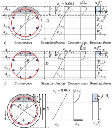
strain; (c) compression bar strain; (d, e, and f) concrete-strain. (Note: 1 kN.m = 0.7376 kip.ft). ... 47 Figure 3.7 Neutral-axis depth. (Note: 1 kN.m = 0.7376 kip.ft). ... 48 Figure 3.8 Idealized cross section and stress and strain distributions in the theoretical
study: (a) first peak moment; (b) second peak moment; (c) proposed
simplified method. ... 58
Figure 3.9 Chart for angle θ on the basis of reinforcement ratio, concrete compressive
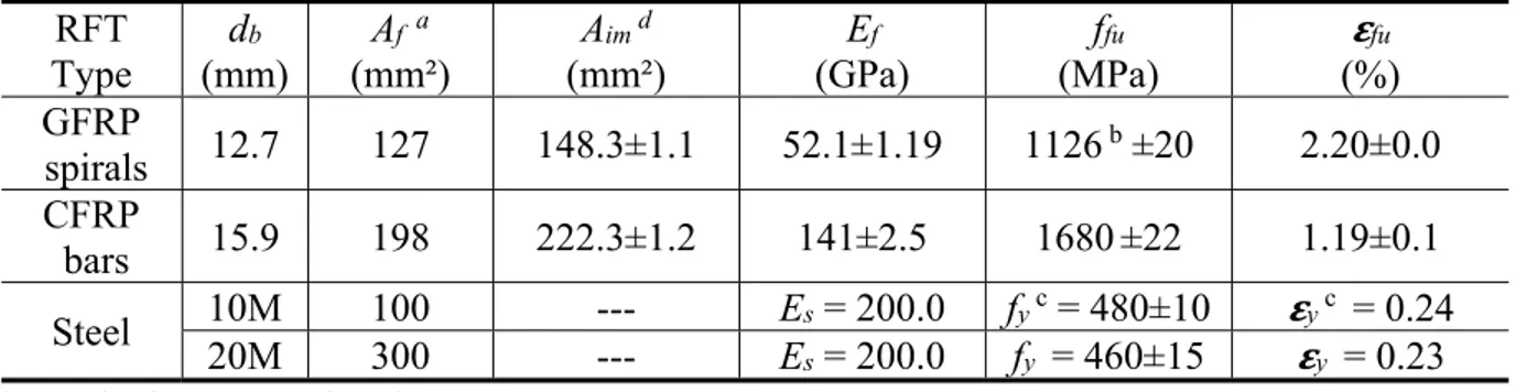
strength, and GFRP modulus of elasticity. ... 58 Figure 4.1 (a) GFRP spirals, (b) CFRP bars, (c) Hybrid CFRP/GFRP cages, and (d)
RC specimens. ... 67 Figure 4.2 Dimensions, reinforcement details, and strain-gauge locations of the test
specimens (dimensions in mm). ... 68 Figure 4.3 Equivalent rectangular section for calculating the balanced reinforcement
ratio, ρfb. ... 71 Figure 4.4 Test setup. ... 72
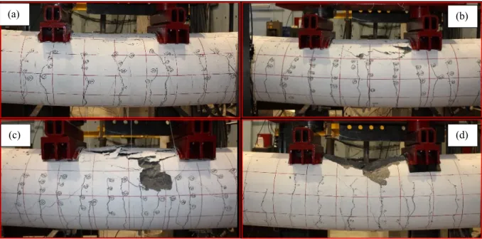
Figure 4.5 Failure modes of the circular hybrid CFRP/GFRP-RC and circular steel-RC
specimen: (a) 8C15, (b) 12C15; (c) 18C15, and (d) 8S20. ... 74
Figure 4.6 Cracking pattern of the test specimens. ... 75
Figure 4.7 Moment–concrete strain relationship at mid-span and at quarter-span. ... 75
Figure 4.8 Moment–bar tension and compression–strain relationship at mid-span. ... 76
Figure 4.9 Effect of axial stiffness of flexural reinforcement on the moment– deflection relationship. ... 78
Figure 4.10 Effect of reinforcement ratio on the moment–deflection relationship. ... 78
Figure 4.11 Moment–bar tension and compression strain along specimen length. ... 79
Figure 4.12 Strain along the mid-span cross-section diameter. ... 80
Figure 4.13 Neutral-axis depth. ... 81
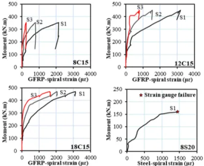
Figure 4.14 Moment–GFRP-spiral strain relationship at the shear span. ... 82
Figure 4.15 Ductility index definition. ... 83
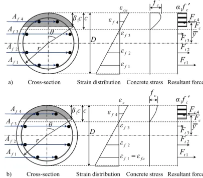
Figure 4.16 Idealized cross section and stress and strain distributions in the analytical model: a) Failure governed by concrete crushing, b) Failure governed by FRP rupture. ... 86
Figure 4.17 Flow chart of the computer program. ... 88
Figure 4.18 Simplified cross-section method and stress and strain distributions: a) Failure governed by concrete crushing, b) Failure governed by FRP rupture. ... 92
Figure 5.1 Dimensions and reinforcement details of the specimens (dimensions in mm). ... 102
Figure 5.2 a) BFRP bars, spirals, and BFRP and steel cages; b) Specimen fabrication. 104 Figure 5.3 Overview of the test setup. ... 106
Figure 5.4 Failure sequence of the BFRP- and steel-reinforced specimens. ... 109
Figure 5.5 Cracking pattern of the specimens at failure. ... 110
Figure 5.6 Influence of reinforcement type on the moment–deflection relationship. ... 111
Figure 5.7 Influence of reinforcement type on the moment–deflection relationship. ... 111
Figure 5.8 Moment–concrete-strain relationship at mid-span. ... 113
Figure 5.9 Moment–concrete-strain relationship at quarter span. ... 113
Figure 5.11 Moment–spiral strain relationship at shear span. ... 115 Figure 5.12 Neutral-axis depth. ... 116 Figure 5.13 Stress–strain curves of the materials used in the analytical model. ... 118 Figure 5.14 Idealized cross section and stress and strain distributions in the analytical
model. ... 120 Figure 5.15 Non-iterative method cross section, stress and strain distributions. ... 124 Figure 5.16 Plans of symmetry and the modeled quarter of specimen... 126 Figure 5.17 ANSYS model (a) Element types, and (b) Loading and boundary
conditions. ... 126 Figure 5.18 Mesh convergence study for specimen 8B20. ... 127 Figure 5.19 Moment–deflection relationship of the verified model against
experimental results. ... 127 Figure 5.20 Deformed shape and crack propagation of the specimens: (a) 8B20; (b)
16B20. ... 128 Figure 5.21 Variation in the moment–deflection relationship with concrete strength. ... 129 Figure 5.22 Variation in the moment–deflection relationship with reinforcement ratio. 129 Figure 6.1 FRP bar types and surface characteristics. ... 142 Figure 6.2 GFRP cages. ... 143 Figure 6.3 Dimensions and reinforcement details of the test specimens. (Note: all
dimensions in mm) ... 145 Figure 6.4 Overview of the test setup. ... 145 Figure 6.5 Typical failure mode of the tested specimens. ... 147 Figure 6.6 Moment–tension-bar strain relationships: (a) Group I versus Group IV, (b)
Group II versus Group IV, (a) Group III versus Group IV. ... 148 Figure 6.7 Cracking pattern of the tested specimens at failure. ... 150 Figure 6.8 Crack width–strain in reinforcement relationships: (a) Group I versus
Group IV, (b) Group II versus Group IV, (a) Group III versus Group IV. .. 153 Figure 6.9 Moment–maximum crack-width relationships: (a) Group I versus Group
IV, (b) Group II versus Group IV, (a) Group III versus Group IV... 154 Figure 6.10 Transformed cracked section, strains, and stresses at service load
Figure 6.11 Definition of the effective depth, d . ... 165 Figure 6.12 Notation of circular cross section according to (a) AASHTO-09, CSA
S6-14, ACI440.1R-15, and JSCE-97; (b) CNR-DT 203/2006. ... 167 Figure 6.13 Comparisons of measured crack widths with AASHTO-09 predictions: (a)
Group I, (b) Group II, (c) Group III. ... 170 Figure 6.14 Comparisons of measured crack widths with CSA S6-14 predictions: (a)
Group I, (b) Group II, (c) Group III. ... 172 Figure 6.15 Comparisons of measured crack widths with ACI440.1R-15 predictions:
(a) Group I, (b) Group II, (c) Group III. ... 173 Figure 6.16 Comparisons of measured crack widths with CNR-DT 203/2006
predictions: (a) Group I, (b) Group II, (c) Group III. ... 174 Figure 6.17 Comparisons of the measured crack widths with JSCE-97 predictions: (a)
Group I, (b) Group II, (c) Group III. ... 175 Figure 6.18 Crack width-axial load level relationship. ... 176 Figure 7.1 Geometry and reinforcement details of the tested circular specimens
(dimensions are in mm). ... 185 Figure 7.2 Test setup. ... 186 Figure 7.3 FRP bar types and surface characteristics. ... 187 Figure 7.4 Load–deflection relationships: (a) GFRP specimens; (b) CFRP specimens;
(c) BFRP specimens. (Note: 1 mm = 0.0394 in.; 1 kN = 0.225 kip) ... 189 Figure 7.5 (a) Overview of deflected shape and failure modes of the tested specimens,
(b) Deflected shape of a simply supported concrete member subjected to two equal concentrated loads. ... 190 Figure 7.6 Transformed cracked section, strains, and stresses at service load. ... 197 Figure 7.7 Effective-to-gross moment of inertia I Ie gversus
M M
a cr. ... 199Figure 7.8 Load–deflection relationships measurements and predictions. (Note: 1 mm = 0.0394 in.; 1 kN = 0.225 kip) ... 202 Figure 7.9 Stress-strain curves of the materials used in the analytical model. ... 205 Figure 7.10 Idealized cross-section and stress and strain distributions in the analytical
Figure 7.11 Experimental vs. analytical model load–deflection relationships of FRP-RC specimens. (Note: 1 mm = 0.0394 in.; 1 kN = 0.225 kip) ... 208
xix
LIST OF TABLES
Page
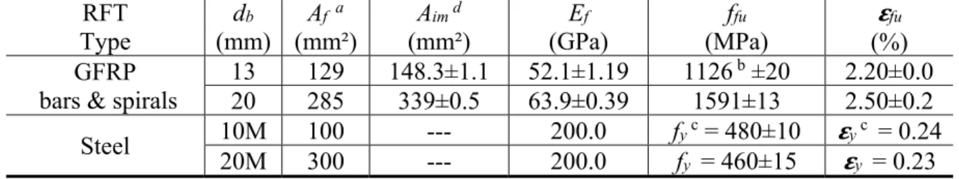
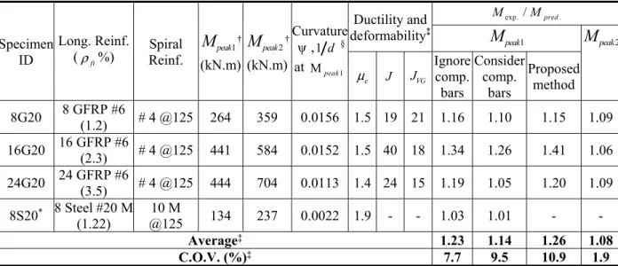
Table 2.1 Typical tensile properties of reinforcing bars (ACI 440.1R-15) ... 11 Table 3.1 Mechanical properties of the GFRP and steel reinforcement ... 37 Table 3.2 Test matrix, test results, curvature, ductility, and deformability of the test
specimens ... 39 Table 4.1 Mechanical properties of the CFRP, GFRP and steel reinforcements ... 66 Table 4.2 Test matrix and details of test specimens ... 68 Table 4.3 Experimental moments, mode of failure, curvature, and ductility and
deformability of test specimens. ... 74 Table 5.1 Test matrix and details of the specimens. ... 103 Table 5.2 Mechanical properties of the BFRP and steel reinforcement. ... 105 Table 5.3 Experimental moments, mode of failure, curvature, and deformability of the
specimens. ... 108 Table 5.4 Normalized flexural capacity of the tested BFRP-RC specimens and the
FRP-RC rectangular beams obtained from past studies. ... 112 Table 6.1 Mechanical properties of the GFRP, CFRP, BFRP, and steel reinforcement. 142 Table 6.2 Test matrix and details of tested specimens. ... 144 Table 6.3 Experimental moments, crack width, strain in reinforcement, and crack
configuration of tested specimens. ... 151 Table 6.4 Experimental to predicted crack width
(
wexp. wpred.)
at service momentusing Approach (1). ... 168 Table 6.5 Experimental to predicted crack width
(
wexp. wpred.)
at service momentusing Approach (2). ... 169 Table 7.1 Test matrix, details of tested specimens, and summary of test results. ... 184 Table 7.2 Mechanical properties of the GFRP, CFRP, and BFRP reinforcement. ... 187 Table 7.3 Experimental-to-predicted deflection
(
δ δexp. pred.)
at the service-load level. .... 2031
CHAPTER 1. INTRODUCTION
1.1. General
Reinforced concrete (RC) members with circular cross sections are frequently used in practice, such as laterally loaded piers and piles in bridge foundations and in jetty substructures for marine and port infrastructure systems. In addition, they are used as secant piling systems for building combined earth-retention and groundwater cutoff walls in deep foundations for buildings and tunnel excavation applications. This is due to the simplicity of construction and because their strength characteristics under lateral loads are similar in all directions. Such members are usually exposed to aggressive environments that corrode the steel reinforcement. The result is structure deterioration, leading to costly repairs and rehabilitation. Estimates indicate that the United States spends billions of dollars annually to repair and replace bridge substructures such as pier columns ($2 billion) and marine piling systems ($1 billion) (Mohamed et al. 2014). The use of fiber-reinforced polymer (FRP) as alternative reinforcing bars in RC structures has emerged as an alternative solution to overcoming the corrosion problem. Since they are noncorroding material, FRP reinforcing bars constitute a better alternative to steel reinforcement. FRP bars have many advantages compared to steel: a density from one-quarter to one-fifth that of steel, neutrality to electrical and magnetic disturbances, and high tensile strength (ACI 440.1R-15).
Extensive research programs have been carried out over the last two decades to investigate the flexural response of FRP-RC members with rectangular sections (ACI 440.1R-15). These studies are greatly improving our knowledge of how rectangular concrete members reinforced with FRP bars should be analyzed and designed. Based on this knowledge, design provisions, equations, and limitations have been developed and included in design guidelines and codes (ACI 440.1R-15; CSA S806-12; CSA S6-14). In contrast, no research seems to have investigated RC members of circular cross section reinforced with FRP bars under flexural loads. Moreover, there are practically no code provisions or guidelines for the flexural design of circular concrete members with FRP reinforcement. ACI 440.1R-15, however, points out that there is no evidence that the flexural theory—developed for rectangular sections—applies
equally well to nonrectangular sections; the behavior of such members has yet to be confirmed experimentally.
In general, the flexural capacity of rectangular members can be easily determined (ACI 440.1R-15; CSA S806-12; CSA S6-14). In contrast to rectangular RC members, the bars in circular RC members are usually distributed in a circle at discrete points, giving rise to some difficulties in calculating the equilibrium of forces and strain compatibility. In addition, the stresses, which are variable over the section depth, are also distributed over an area of variable width. This fact leads to a very small part of the circular section exhibiting a maximum compression strain. On the other hand, the extreme tension reinforcement might reach the ultimate strain and stress, while the other layers of reinforcement have lower stresses, possibly equal to zero in proximity to the neutral axis. This produces a larger concrete compression zone and a smaller internal lever arm when compared to rectangular sections with equivalent dimensions. As a result of this behavior, smaller flexural capacities might be obtained in members with circular sections when compared to those with rectangular sections.
Crack control is an important serviceability criterion in the design of concrete members reinforced with FRP bars. Crack-width limits under service loads can govern the design of FRP-RC members. On the other hand, FRP bars are corrosion-resistant, so larger crack widths can be tolerated in FRP-RC members than in steel-RC members when reinforcement corrosion is the primary reason for crack control. Other considerations with regards to acceptable crack-width limits include aesthetics, creep rupture, and shear effects (ACI 440.1R-15). Crack spacing and crack width in RC members are dependent on many design parameters, including FRP-bar bond characteristics, the ratio of reinforcement area to surrounding concrete area, tensile strain in FRP bars, bar spacing, and concrete tensile strength. The bond capacity between FRP bars and concrete depends on concrete cover, bar size, surface treatments, concrete strength, and modulus of elasticity of FRP bars. Significant research has been carried out over the last two decades to determine relationships between concrete crack width and the aforementioned design parameters in FRP-RC members. The experimental work has focused mainly on beams with rectangular cross sections (Faza and GangaRao 1993; Masmoudi et al. 1996; Theriault and Benmokrane (1998); Toutanji and saafi 2000; Toutanji and Deng 2003; El-Salakawy and Benmokrane 2004; Ospina and Bakis 2007; El-Nemr et al. 2013 and 2016; Noel and Soudki
2014; Elgabbas et al. 2016 and 2017; Barris et al. 2017). In these studies, crack widths were predicted with the empirically proposed Gergely-Lutz 1968 equation and Frosch’s 1999 physical model. Since crack width is a function of reinforcement stiffness and bond properties, the effect of the reinforcement type is significant. Hence, various modifications to the steel-based models have been proposed to account for the mechanical properties of FRP reinforcing bars (Faza and GangaRao 1993; Masmoudi et al. 1998; Toutanji and saafi 2000; Ospina and Bakis 2007; Noel and Soudki 2014). In addition, several design codes and guidelines have been published to control the cracks in rectangular FRP-RC members: AASHTO (2009), CSA S6 (2014), ACI 440-1R (2015), CSA S806 (2012), CNR-DT 203 (2006) and JSCE (1997). In contrast, studies on the cracking behavior of circular concrete members that can be reinforced with FRP bars have not yet been introduced.
Deflection control is an important performance criterion that needs to be satisfied to ensure the serviceability of fiber reinforced polymer (FRP) reinforced concrete (RC) structures. Under similar circumstances, in terms of concrete strength, applied loads, identical size, and reinforcement layout, FRP-RC members are expected to develop larger deformations than steel RC members due to the variable stiffness, linear elastic behavior, and particular bond features of FRP reinforcement (ACI 440.1R-15). Deflections of flexural members are commonly computed using an elastic deflection equation in conjunction with an effective moment of inertia
e
I , a concept that empirically provides a transition between the upper and lower bounds of gross
moment of inertia, I , and cracked moment of inertia,g Icr, as a function of the ratio of cracking
to applied moment, Mcr Ma. Several authors have proposed coefficients to modify Branson’s
equation to simulate the real behavior of rectangular FRP-RC members (Benmokrane et al. (1996); Theriault and Benmokrane (1998); Alsayed et al. (2000); Toutanji and Saafi (2000); Yost et al. (2003); Mousavi and Esfahani (2012); Adam et al. (2015)). Others have proposed deflection calculation models that derived from integration of curvatures (Razaqpur et al. (2000); Bischoff (2005, 2007); Bishcoff and Gross (2011a, b)). Based on these different approaches, equations for calculating deflections of FRP-RC members have been included in design guidelines and codes (ACI 440.1R-15; CSA S806-12; CNR-DT 203/2006). These models and code provisions were developed mainly based on experimental work on FRP-RC members with rectangular sections. Despite the valuable applications of circular RC members,
no research seems to have investigated RC members of circular cross-section reinforced with FRP bars.
This research intended to originally examine the flexural performance and serviceability of concrete members with circular sections and reinforced with FRP bars and spirals.
1.2. Research significance
Over the last two decades, substantial number of experimental research studies and discussions have been published related to the flexural behavior and serviceability of FRP-RC members with rectangular sections (ACI 440.1R-15). So far, this research is the first testing program aimed at investigating the flexural strength and serviceability of full-scale circular concrete members reinforced with GFRP bars and spirals. The results will contribute to implementing the use of FRP bars in circular concrete piles, which can be an innovative solution to the corrosion problem in infrastructure applications. This study also provides new insights into the analysis and design of circular concrete members reinforced with FRP reinforcements with an extensive theoretical study. The experimental data and design analysis provide the evidence required to include design provisions in the forthcoming ACI 440 code and updated CSA S6 code for the use of FRP bars and spirals as internal reinforcement in circular members under flexure.
1.3. Research objectives
This paper describes the results from nine full-scale circular RC members tested under four-point bending, including three specimens reinforced internally with GFRP, which is the most common type of FRP due to its cost effectiveness; three specimens reinforced with CFRP bars; two specimens reinforced with BFRP bars; and one reinforced with steel for comparison purposes. The main objective of this investigation is to examine the feasibility and efficiency of using FRP bars and spirals in circular RC members under flexural load. A number of specific research objectives were identified and are listed below.
1- To investigate the effect of the FRP reinforcement ratio on flexural strength and serviceability of circular FRP-RC members.
3- To assess the ductility and deformability of such members.
4- Assess the accuracy of the current FRP design provisions that were developed on rectangular sections for estimating the flexural strength, crack control, and deflection of the tested circular specimens, including ACI 440-1R-15, AASHTO-09, CSA S6-14, JSCE (1997), and Italian National Research Council CNR-DT 203/2006.
5- To propose simple and accurate design procedures for predicting the flexural strength, crack control, and deflection of circular FRP-RC members.
6- To develop a reliable analytical 3-D model using non-linear finite element analysis program (ANSYS) to predict the behavior and flexural capacity of circular FRP-RC members.
1.4. Research methodology
To achieve the objectives of this research, extensive experimental and analytical programs were designed. The experimental program was conducted to investigate the flexural behavior and serviceability of concrete members with circular section and reinforced with FRP bars and spirals. A total of nine large-scale specimens with a total length of 6,000 mm and 500 mm in diameter were constructed and tested under four-point bending. Testing was intended to assess the flexural strength of circular FRP-RC members, so all of the specimens were designed such that their shear strength exceeded their flexural strength. This was achieved by reducing the shear influence and choosing a shear span-to-depth ratio greater than five (Kani 1964). The current study addressed the worst (critical) case when the flexural demand prevails over the axial load in columns, piles and piers. In addition, there are some applications for using a circular section, such as soft-eyes in tunnels and fender piles in marine structures that are usually subjected to pure bending moment without axial load. The test parameters included the longitudinal-reinforcement ratio and the longitudinal-reinforcement type, including three specimens reinforced internally with GFRP, which is the most common type of FRP due to its cost effectiveness; three specimens reinforced with CFRP bars; two specimens reinforced with BFRP bars; and one reinforced with steel. It should be noted that only two specimens were reinforced with newly produced BFRP bars for comparison purposes with specimens reinforced
with GFRP and CFRP bars. The experimental results were reported in terms of moment– deflection behavior, flexural capacity, mode of failure, crack patterns, crack spacing, and crack widths. The ductility and deformability of the test specimens were estimated using different approaches. An analytical strain-compatibility model capable of predicting the flexural strength of circular FRP-RC members, including the sequential progressive failure, was developed and verified with the experimental results. Moreover, a simplified method including design equations, design chart, and step-by-step design procedures were presented using non-iterative analysis. In addition, the finite element model developed predicted the response of tested specimens with a reasonable degree of accuracy and was used to extend the range of investigated parameters. On the other hand, crack-control models in the current FRP codes and design guidelines were reexamined, extended, and applied to circular FRP-RC members. Finally, the measured deflections and experimental values of the effective moment of inertia
( )
I were eanalyzed and compared with those predicted using available models.
1.5. Dissertation Layout
The dissertation consists of eight chapters. The contents of each chapter can be summarized as follows:
Chapter 1 presents the introduction, research significance, objectives, and methodology of this study.
Chapter 2 provides a brief summary of the main characteristics and properties of the FRP materials used as internal reinforcement. The main studies that investigated the flexural behavior and serviceability of concrete members reinforced with FRP bars. The code provision that related to flexural behavior and serviceability of FRP reinforced concrete members are also presented.
Chapter 3 (1st article) investigates the flexural strength and behavior of concrete members with
circular section and reinforced with GFRP bars and spirals both experimentally and theoretically. The test parameters included reinforcement flexural stiffness (GFRP versus steel) and GFRP longitudinal-reinforcement ratio. Ductility and deformability of the tested specimens were calculated and evaluated. An analytical strain-compatibility model capable of predicting the flexural strength of circular GFRP-RC members, including the sequential progressive
failure, was developed and verified with the experimental results. Moreover, a simplified method, including design equations and design chart, was presented using non-iterative analysis [Reference: Mousa, S., Mohamed, H. M., and Benmokrane, B. (2018) “Flexural Strength and Design Analysis of Circular RC Members with GFRP Bars and Spirals.” ACI Structural
Journal, accepted].
Chapter 4 (2nd article) reports on a study in which the flexural strength and deformability of
circular concrete members with hybrid reinforcement—CFRP bars and GFRP spirals—were assessed experimentally and analytically. Detailed design procedures using a computer program were proposed for estimating the flexural capacity of circular CFRP-RC members using A Microsoft Excel Spreadsheet. The experimental and analytical results were discussed and compared [Reference: Mousa, S., Mohamed, H. M., and Benmokrane, B. (2018) “Strength and Deformability Aspects of Circular Concrete Members Reinforced with Hybrid Carbon-/Glass-FRP Reinforcement under Flexure.” submitted to Journal of Composites for Construction, ASCE, under review].
Chapter 5 (3rd article) reports on the experimental results of flexural tests on full-scale circular
RC members with BFRP reinforcement, followed by an intensive analytical study and finite-element analysis. The main investigated parameters were the ratio and type of longitudinal reinforcement. An analytical model was developed using a layer-by-layer approach to estimate the flexural strength of the tested specimens. In addition, the finite-element model developed predicted the response of the tested specimens with a reasonable degree of accuracy and was used to extend the range of the investigated parameters [Reference: Mousa, S., Mohamed, H. M., Benmokrane, B., and Ferrier, E. (2018) “Flexural Behavior of Full-Scale Circular Concrete Members Reinforced with Basalt FRP Bars and Spirals: Tests and Theoretical Studies.”
Composite structures, 203, 217-232].
Chapter 6 (4th article) investigates the cracking and crack control of circular FRP-RC members
experimentally and theoretically. The experimental results are reported in terms of crack patterns, crack spacing, and crack width versus flexural tension-bar strain and the applied moment. Crack-control models in the current FRP codes and design guidelines were reexamined, extended, and
B. (2018) “Cracking and Crack Control in Circular Concrete Bridge Members Reinforced with
Fiber-Reinforced-Polymer (FRP) Bars.” Journal of Bridge Engineering, ASCE, accepted].
Chapter 7 (5th article) investigates serviceability performance in terms of deflection predictions
of circular FRP-RC members experimentally and theoretically. The measured deflections and
experimental values of the effective moment of inertia
( )
Ie were analyzed and compared withthose predicted using available models in the literature, as well the models included in the design guidelines and codes. Based on the analysis of the test results, a new equation was developed to accurately predict the deflection of the tested circular specimens. Moreover, an analytical model has been developed by using a layer-by-layer curvature analysis approach based on cross-sectional analysis satisfying strain compatibility and equilibrium conditions [Reference: Mousa, S., Mohamed, H. M., and Benmokrane, B. (2018) “Deflection Prediction Methodology for Circular RC Members Reinforced with FRP Bars.” submitted to ACI
Structural Journal, accepted].
9
CHAPTER 2. LITERATURE REVIEW
2.1. General
This chapter provides a brief summary of the main characteristics and properties of the Fiber-reinforced polymer (FRP) materials used as internal reinforcement. This is followed by a demonstration of the main studies that investigated the flexural behavior and serviceability of concrete members reinforced with FRP bars. The code provision that related to flexural behavior and serviceability of FRP reinforced concrete members are also presented.
2.2. FRP Materials
2.2.1. FRP Constituent materials
FRP is a specific type of two-component composite material consisting of high strength fibers embedded in a polymer matrix. As the FRP materials are composed of two distinct materials, overall FRP material properties depend primarily on those of the individual constituents. The fibers are significantly stronger than the resin material and control the elastic modulus and final strength of the composite. The mechanical properties of the final FRP product depend on a number of parameters. This includes fiber type, quality, volumetric ratio, adhesion resin and most importantly the manufacturing process (ACI 440.1R-15).
2.2.1.1. Fibers
The fibers provide the strength and stiffness of FRP. Because the fibers used in most structural FRP applications are continuous and are oriented in specified directions, FRP materials are orthotropic, and they are much stronger and stiffer in the fiber direction(s). Fibers are generally selected to have high stiffness, high ultimate strength, low variation of strength between individual fibers, stability during handling, and uniform diameter. In civil engineering applications, the most commonly used fiber types are glass, carbon, aramid, and recently basalt fibers. The suitability of the various fibers for specific applications depends on a number of factors including the required strength, stiffness, durability considerations, cost constraints, and the availability of component materials.
2.2.1.2. Resins
The resin (matrix) is the binder of the FRP and plays many important roles. Some of the more critical functions played by the matrix are to bind the fibers together, protect the fibers from abrasion and environmental degradation, separate and disperse fibers within the composite, and transfer the forces between the individual fibers. Matrix materials for FRPs can be grouped into two broad categories: thermoplastics and thermosetting resins. Thermoplastics include such polymer compounds as polyethylene, nylon, and polyamides, while thermosetting materials include Polyesters, epoxies, and vinylesters.
2.2.2. Manufacturing process
There are three main manufacturing processes for FRP composites; pultrusion, braiding, and filament winding (ISIS Canada 2007). Pultrusion is a common technique for manufacturing continuous lengths of FRP bars that are of the constant or nearly constant profile. A schematic drawing of this technique is shown in Fig. 2.1. Continuous strands of reinforcing material are drawn from creels, through a resin tank, where they are saturated with resin, and then through a number of wiper rings into the mouth of a heated die. The speed of pulling through the die is predetermined by the curing time needed. To ensure a good bond with concrete, the surface of the bars is usually braided or sand-coated.
2.2.3. FRP products as internal reinforcement
FRP reinforcing bars are manufactured from continuous fibers (such as carbon, glass, aramid, and basalt) embedded in matrices (thermosetting or thermoplastic). Similar to steel reinforcement, FRP bars are produced in different diameters, depending on the manufacturing process. FRP materials are anisotropic and are characterized by high tensile strength with no yielding only in the direction of the reinforcing fibers (ACI 440.1R-15). The tensile behavior of FRP bars consisting of one type of fiber material is characterized by a linearly elastic stress-strain relationship until failure. Compared to ductile steel, FRPs generally have higher tensile capacity and relatively lower modulus of elasticity. Table 2.1 summarizes the typical mechanical tensile properties of FRP bars compared to those of steel reinforcement. More details about various properties of FRP reinforcement can be found in other publications (ACI 440.1R-15; AASHTO-09).
Table 2.1 Typical tensile properties of reinforcing bars (ACI 440.1R-15)
Properties Steel GFRP CFRP AFRP
Nominal yield stress, MPa 276 to 517 N/A N/A N/A
Tensile strength, MPa 483 to 1600 483 to 690 600 to 3960 1720 to 2540
Elastic modulus, GPa 200 35 to 51 120 to 580 41 to 125
Yield strain, percent 0.14 to 0.25 N/A N/A N/A
Rupture strain, percent 6.0 to 12.0 1.2 to 3.1 0.5 to 1.7 1.9 to 4.4
2.3. Flexural behavior and strength of rectangular FRP-RC members
2.3.1. Flexural capacity of rectangular FRP-RC members
The theoretical flexural capacity of rectangular FRP-RC members can be calculated based on the principles of force equilibrium and strain compatibility between the concrete and FRP bars. The design philosophy is based on the following assumptions:
1. Strain in the concrete and the FRP reinforcement is proportional to the distance from the neutral axis (a plane section remains plane after deformation up to failure).
2. The maximum usable compressive strain in the concrete is assumed to be 0.003 as per ACI 440.1R-15 or 0.0035 as per CSA S806-12.
4. The tensile behavior of the FRP reinforcement is linearly elastic until failure.
5. The strain in the FRP reinforcement, whether in tension or compression, is the same as that in the surrounding concrete (i.e. perfect bond exists between the FRP reinforcement and concrete).
6. The distribution of concrete compressive stress can be described by the equivalent rectangular stress block shown in Fig. 2.2 with parameters α1 and β1, calculated from Eqns. (2.1.a and b) for ACI 440.1R-15 and Eqns. (2.2.a and b) for CSA S806-12:
1 0.85
α
= (2.1.a)(
)
1 0.05 28 0.85 0.65 7 c f β = − ′− ≥ (2.1.b) 1 0.85 0.0015fc 0.67α
= − ′≥ (2.2.a) 1 0.97 0.0025fc 0.67β
= − ′≥ (2.2.b)Flexural design of concrete members reinforced with FRP bars is based on strain compatibility and depends on whether the failure is governed by rupture of the tensile reinforcement or concrete crushing. There are three possible modes of flexural failure are available for concrete member reinforced with FRP bars:
- Balanced failure: simultaneous rupture of FRP and crushing of concrete;
- Compression failure: concrete crushing while FRP remains in the elastic range with a strain level smaller than the ultimate strain; and,
- Tension failure: rupture of FRP in which FRP reaches its ultimate strain level before concrete crushing.
The mode of failure can be determined theoretically by comparing the reinforcement ratio
( )
ρfwith the balanced reinforcement ratio
( )
ρfb . The FRP reinforcement ratio can be computed fromreinforcement ratio is less than the balanced ratio (ρ ρf < fb), the FRP rupture limit state controls. Otherwise, (ρ ρf > fb) the concrete crushing limit state controls.
f f A bd ρ = (2.3) 1 1 c f cu fb fu f cu fu f E f E f ε ρ α β ε ′ = + (2.4)
where fc′ is the specified compressive strength of concrete; ffu and Ef are the ultimate tensile
strength and modulus of elasticity of FRP bars, respectively; and
ε
cu is the maximum usablecompressive strain in the concrete.
Most of the current codes and design guidelines recommended the compression failure for the design of flexural members reinforced with FRP bars (CSA-S806-12; ACI 440.1R-15). ACI 440.1R-15, however, accepts both failure modes (compression failure or tension failure) if strength and serviceability criteria are satisfied. On the other hand, CSA S806-12 accepts the tension failure mode if the factored resistance of a section is greater than 1.6 times the effect of the factored loads.
When ρ ρf > fb, the controlling limit state is crushing of the concrete, and the stress distribution in the concrete can be approximated with a rectangular stress block. Based on the equilibrium of forces and strain compatibility (shown in Fig. 2.2).
Figure 2.2 Strain and stress distribution at the ultimate condition.
The nominal flexural strength of a section can be expressed in terms of the FRP reinforcement ratio, as given in Eq. 2.5 (ACI 440.1R-15).
2 1 0.59 f f n f f f f M f bd f ρ ρ = − (2.5)
When ρ ρf < fb, the controlling limit state is rupture of the FRP reinforcement, and the nominal flexural strength of a section can be computed as shown in Eq. 2.6 (ACI 440.1R-15).
1 2 n f fu c M = A f d−β (2.6)
With regards to the available experimental results on FRP-RC members, Benmokrane et al. (1996); Masmoudi et al. (1998); and Theriault and Benmokrane (1998) reported that the ultimate
moment was 15% underestimated by ACI 440.1R formula when the section failed by compression failure, but it was 5% overestimated in the case that the section failed by tension failure. This difference was attributed to the variability of the compressive strength of concrete and tensile strength of the FRP reinforcing bars.
Rafi et al. (2008) found that ACI 440.1R formulations underestimated the moment capacity of their four tested FRP beams to about 33%, probably because the actual strain in concrete exceeded the maximum concrete strain of 0.003 as a result of the confinement provided especially by the stirrups.
Barris et al. (2009) reported that for their tested beams the experimental ultimate load was 51% higher than expected according to ACI 440.1R predictions. This difference probably occurred because the ultimate concrete compressive strain observed in the experiments was higher than the value indicated by the theoretical approaches.
2.3.2. Parameters affecting moment capacity of FRP-RC members
2.3.2.1. Effect of reinforcement ratio
Masmoudi et al. (1998) and Theriault and Benmokrane (1998) stated that as the reinforcement ratio increases, the ultimate moment capacity increases, but this increase is limited by the concrete compressive failure strain of over-reinforced concrete beams.
Kassem et al. (2011) reported concrete crushing in FRP-RC beams, whereas the increased ρ f
did not significantly increase the flexural capacity. The increases were 4 and 16% when ρ was f
increased by 50 and 100%, respectively.
El-Nemr et al. (2013) found that in the case of the normal strength concrete (NSC) beams,
increasing ρ from 0.36 to 1.47% increased the load-carrying capacity by 143%. Increasing f ρ f
from 0.55 to 1.78% increase the capacity by 224%. Increasing ρ by three to four times resulted f
in an average increase of 83.5% in the load-carrying capacity. Similarly, for the HSC beams,
increasing ρ from 0.36 to 1.47% and from 0.55 to 1.78% increased the ultimate load-carrying f
2.3.2.2. Effect of concrete strength
Theriault and Benmokrane (1998) stated that as the concrete strength increases, the ultimate moment capacity increases, but this increase is limited by the concrete compressive failure strain of over-reinforced concrete beams. Similar remarks have been made by Nanni (l993), who reported that the maximum moment capacity is highly variable because it depends on the concrete maximum strain.
Yost and Gross (2002) reported that using higher concrete strength resulted in the more efficient use of the FRP. For some of their tested beams, increasing the concrete strength increased the ultimate load-carrying capacity. The increased ratio was not consistent because of the lower measured concrete strains at failure.
2.3.2.3. Effect of FRP reinforcement surface
Nanni (1993) studied the flexural behavior of concrete beams reinforced with different GFRP bars (smooth or sand-coated) and steel deformed bars. It was noted that the sand-coated FRP increased the ultimate flexural capacity by approximately 25% compared with the equivalent uncoated rebars. The authors state that the ultimate strength could be predicted on the basis of the material properties of the concrete and reinforcement. On the other hand, Kassem et al. (2011) indicated that the surface texture played no role in beam flexural capacity when sand-coated bars and ribbed-surface bars were used.
2.4. Ductility and deformability
Ductility is a structural-design requirement in most design codes. The traditional definition of ductility for steel-reinforced concrete members, which considers the yielding of steel bars as a reference point, cannot be directly applied to members reinforced with FRP reinforcement due to the linear-elastic behavior of the FRP bars up to failure. Several methods have been proposed to calculate the ductility of FRP-RC structures. These methods can be divided into three categories depending on the approach used:
• Deformability factor
• Curvature-based deformability index
2.4.1. Energy-Based Ductility Index
Naaman and Jeong (1995) defined ductility as the ratio of the total energy to the elastic energy
and proposed the following equation to compute the ductility index, μe, which can be applied
to steel- and FRP-RC members: 1 1 2 tot e el E E
μ
= + (2.7)where Etot= the total energy computed as the area under the load-deflection curve, and Eel = the elastic energy released upon failure computed as the area of the triangle formed at failure load by the line having the weighted average slope of the two initial straight lines of the load-deflection curve, as shown in Fig. 2.3.
Figure 2.3 Ductility index definition.
2.4.2. Deformability Factor
The Canadian Highway Bridge Design Code (CAN/CSA S6-14) adopted the Jaeger et al. 1997 (J-factor) approach to evaluate the deformability index of FRP-RC members. In this approach, the absorbed energy is measured based on deformability rather than ductility to ensure adequate deformation of FRP-reinforced structures before failure. The deformability J-factor takes into
account the strength effect as well as the curvature effect at service and ultimate conditions. The deformability J-factor can be calculated as follows:
ultimate ultimate c c M J M ψ ψ = × (2.8)
where ψc= curvature at a concrete strain equal to 0.001 (service condition); ψultimate = curvature
at ultimate; M = moment at concrete strain equal to 0.001; c Multimate = ultimate moment. CSA
S6-14 requires a J-factor exceeding 4 and 6 for rectangular sections and T-sections, respectively, with no recommendation for circular sections.
2.4.3. Curvature-Based Deformability Index
Vijay and GangaRao (2001) defined the deformability factor as the ratio of energy absorption
(area under moment–curvature curve or area under the load-deflection curve) at ultimate, E , tot
to energy absorption at a limiting curvature value of 0.005/d, Eψ=0.005/d, which satisfies the serviceability criteria of both deflection and crack width.
0.005/ tot V G d E J Eψ= = (2.9)
2.5. Serviceability performance of rectangular FRP-RC members
Serviceability can be defined as satisfactory performance under service load conditions. FRP-RC members have a relatively small stiffness after cracking when compared to steel-FRP-RC members with the same reinforcement ratio. Consequently, permissible deflections under service loads can control the design. In general, designing FRP-reinforced cross sections for flexural strength may not satisfy serviceability criteria for crack control and deflection.2.5.1. Crack control of FRP-RC members
Crack control is an important serviceability criterion in the design of concrete members reinforced with FRP bars. Crack-width limits under service loads can govern the design of FRP-RC members. On the other hand, FRP bars are corrosion-resistant, so larger crack widths can be tolerated in FRP-RC members than in steel-RC members when reinforcement corrosion is
the primary reason for crack control. Other considerations with regards to acceptable crack-width limits include aesthetics, creep rupture, and shear effects (ACI 440.1R-15).
Cracking control of RC flexural members is mainly developed for steel RC members with rectangular sections, based on empirical models of analyzing experimental data (Gergely and Lutz 1968) or on a physical model by multiplying the crack spacing by the mean strain of flexural reinforcement (Frosch 1999). For the cracking control of FRP-RC members, design equations and prediction models are generally based on similar formulation to that of steel rectangular reinforced concrete members, with coefficients that depend on the different characteristics of the FRP bars and their interaction with concrete
In 1993, Faza and GangaRao replaced steel strain with FRP strain in Gergley-Lutz equation to predict the crack width of FRP-RC members. Masmoudi et al. (1996) carried out an experimental investigation on the cracking behavior of concrete beams reinforced with fiber reinforced plastic rebars. The effects of reinforcement ratio on the cracking pattern, crack spacing, cracking moment, and crack width were investigated. The authors showed that as the reinforcement ratio increases, the number of cracks increases and the crack spacing decreases. However, they found that the effect of the reinforcement ratio on cracking moment was negligible. In addition, the authors introduced a coefficient in the Gergely-Lutz equation to account for the bond characteristics of FRP bars. The predictions of the modified model compared well to the test results achieved by Theriault and Benmokrane (1998).
Theriault and Benmokrane (1998) tested 12 concrete beams reinforced with FRP bars. The main parameters investigated in this study were the reinforcement ratio and the concrete strength. The authors concluded from their work that the effect of the concrete strength and the reinforcement ratio on the crack spacing is negligible, and the crack spacing slightly decreases as the load increases. The higher the concrete strength is, the wider the crack for the same applied moment. Moreover, Theriault and Benmokrane (1998) explained that those wider cracks are due to the release of greater stress at crack initiation, followed by a sudden crack formation. However, the reinforcement ratio shows a strong influence on the crack width: A smaller crack width is obtained by means of a higher reinforcement ratio.