Open Archive TOULOUSE Archive Ouverte (OATAO)
OATAO is an open access repository that collects the work of Toulouse researchers and makes it freely available over the web where possible.This is an author-deposited version published in: http://oatao.univ-toulouse.fr/ Eprints ID: 19940
To link to this article: DOI: 10.4028/www.scientific.net/SSP.260.85 URL: https://doi.org/10.4028/www.scientific.net/SSP.260.85
To cite this version : Jodin, Gurvan and Scheller, Johannes and Duhayon, Eric and Rouchon, Jean-François and Braza, Marianna Implementation of a hybrid electro-active actuated morphing wing in wind tunnel. (2017) Solid State Phenomena, vol. 260. pp. 85-91. ISSN 1662-9779
Any correspondence concerning this service should be sent to the repository administrator: [email protected]
Implementation of a hybrid electro-active actuated morphing wing in
wind tunnel
Gurvan JODIN
1, 2, a, Johannes SCHELLER
3, b, Eric DUHAYON
1,c,
Jean-François ROUCHON
1,dand Marianna BRAZA
2,e1LAPLACE, 2, Rue Charles Camichel, - BP 7122, F-31071 Toulouse, France 2IMFT, 1, Rue du professeur Camille Soula, F-31400 Toulouse, France
3MIT, 77 Massachusetts Ave, Cambridge, MA 02139, USA
a[email protected], b[email protected], c[email protected], d[email protected], e[email protected]
Keywords: Aerodynamics, Morphing, Piezoelectricity, Shape-memory Alloys, Control.
Abstract. Amongst current aircraft research topics, morphing wing is of great interest for improving
the aerodynamic performance. A morphing wing prototype has been designed for wind tunnel experiments. The rear part of the wing - corresponding to the retracted flap - is actuated via a hybrid actuation system using both low frequency camber control and a high frequency vibrating trailing edge. The camber is modified via surface embedded shape memory alloys. The trailing edge vibrates thanks to piezoelectric macro-fiber composites. The actuated camber, amplitude and frequency ranges are characterized. To accurately control the camber, six independent shape memory alloy wires are controlled through nested closed-loops. A significant reduction in power consumption is possible thanks this control strategy. The effects on flow via morphing have been measured during wind tunnel experiments. This low scale mock-up aims to demonstrate the hybrid morphing concept, according to actuator capabilities point of view as well as aerodynamic performance.
Introduction
Nowadays the public considers the environmental compatibility of aircraft an important issue. The airline companies demand for more economic aircrafts. This leads to the design of more efficient aircrafts. With respect to the aerodynamic performance, current planes have their wings optimized for one cruise flight step. But during a flight, the altitude, the weight and the speed is still changing so one fixed wing shape is sub-optimal. It has been shown that changing the shape of the wing can save several percent of burn fuel for a regional passenger aircraft, [8]. Additionally, a wing with a fixed leading edge and a shape adaptation limited to the trailing edge leads to performances closed to a fully adaptive wing.
As the benefits of morphing wings are known, the ways to obtain it are a subject of intense research. Actuation system weigh, safety and reliability are examples of common issues. Some research focuses on relatively high Technology Readiness Level (TRL) targeting current industrial
airliners at true scale. One interesting European research program which focuses on cost reductions
as well as improving the aerodynamic performance is SARISTU4. One work package deals with a morphing wing trailing edge, [4]. The device is based on servomotors driving an articulated structure. To allow deformations whilst keeping a smooth shape, elastomeric joints are used. Another trailing edge morphing concept has been developed by NASA in cooperation with FlexSys Inc. Endurance flight tests are currently done, [6]. The Adaptive Compliant Trailing Edge flaps demonstrates the ability of a compliant structure to be actuated and deformed. This innovative flap has demonstrated aerodynamic benefits and now its effectiveness and airworthiness are tested.
However these new adaptive structures are actuated through conventional actuators like servomotors.
Recent advances in the field of smart materials show the potential to overcome difficulties to make a wing both stiff enough to withstand the loads and flexible enough to be easily deformed, [2]. A complex multidisciplinary approach is required, this can explain the relatively low TRL of morphing using smart materials. Research focuses on low scale like Micro Air Vehicles. Considering electroactive materials, Shape Memory Alloys (SMAs) and piezoelectric materials are commonly used. SMAs are characterized by thermomechanical behaviors, and most of applications use Joule heating to activate the SMAs. Diverse morphing concepts have been developed, [1]. Typical applications are shape adaptation at low deformation speed. Some SMA are able to carry more than 400MPa and can recover strain of over 4% and researches show the ability of SMAs to reach one million actuation cycles, [5]. Piezoelectric materials' electromechanical behavior is activated via electric field, [2]. The most used material is lead zirconate titanate (PZT) ceramic. The developments of piezoelectric composites allows for a simple implementation; piezoelectric composite patches glued on structure are often used as bending actuators that control the shape of a wing. Despite the PZT ceramics are brittle, they provide high frequency actuation with an excellent life cycle. The previously cited works generally realize the desired function using one specific smart material.
A combination of both SMAs and PZT can enhance the global performance. The synergistic smart morphing aileron [9] is the combination of a SMA actuated hinge followed by a flexible piezoelectric driven trailing edge.
As part of collaborative effort from two laboratories (LAPLACE and IMFT), a SMA actuated plate was developed for wind tunnel purpose, [3]. Then a prototype NACA0012 wing with a vibrating trailing edge was experimentally investigated in wind tunnel. It has been shown that the trailing edge vibration interacts with the shear layer. The wing's wake energy has been reduced, leading to an improvement in aerodynamic performance, [10]. The next part of the research was a NACA 4412 wing, developed with embedded SMA and trailing edge piezoelectric fiber actuators, [12]. This allowed both large deformations (~10% of the chord) at limited frequency (≤ 1[Hz]) and small deformations (several [mm]) at high frequencies (≤ 100[Hz]). This actuation concept is called hybrid electroactive morphing wing.
To the authors' knowledge, the originality of the present work is the study of the links between camber control and a vibrating trailing edge. The previous works targeted MAV scale aircraft. The purpose of this paper is the up-scaling towards commercial passenger airliners. In cooperation with Airbus, a first step is to size, design, make and test a small scale mock-up of a wing with an innovative flap design. This flap still reaches classic high lift function. New functions like drag reduction, shape optimization and noise reduction are addressed through hybrid electroactive morphing.
This paper first introduce the purpose of the prototype and the design of the two actuation systems. Then the experimental set-up is described, including wind tunnel experiments and sensors. The third part presents experimental results. Electromechanical characterization and control influence during wind tunnel experiments are exposed. Finally a conclusion of this prototype presenting the future work is drawn.
Actuators design
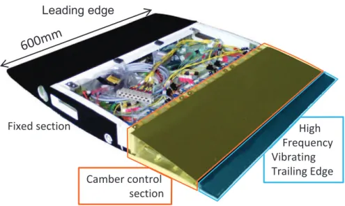
Main prototype purpose. The morphing wing embeds both camber control and High Frequency
Vibrating Trailing Edge (HFVTE) actuators. Fig. 1 presents the hybrid morphing prototype. The actuators have been sized, simulated and made. This mechatronic prototype aims the sizing models validation. The 6 months wind tunnel experiment campaign has been a way to understand fatigue life and morphing wing behavior in every experimental condition. But this experimental campaign aims primarily at the investigation of morphing effects on the airflow. Different flow conditions
have been tested. This prototype is designed for a wide range of morphing; this means the actuators' specification aim to test as many different morphing configuration as possible.
High Frequency Vibrating Trailing Edge (HFVTE). The HFVTE main specifications are: a
static trailing edge displacement closed to 1[mm], a first resonance frequency over 100[Hz] and respecting the airfoil shape. To fulfill these requirements, piezoelectric composite patches are glued on both sides of a metallic substrate. To generate the movements, the patches are alternatively activated. Due to the substrate thickness, the patches' forces create an alternative bending moment that makes the beam vibrating. To respect the airfoil shape, the assembly is covered by a silicone shell, as show in Fig. 2(a).
Fig. 2: HFVTE actuator
One can model the electromechanical behavior of the vibrating piezoelectric beam, [11]. As the input is the applied voltage and the output is the tip displacement, the transfer function is a sum of second order models. A notable property is the amplitude plateau at low frequency below the first resonance mode. As we want a large bandwidth to explore morphing effects on airflow, the static displacement and first resonance frequency are specified.
The design process is conducted twofold. Using [11], the actuator without silicone cover is design to reach maximum performance in the constrained space. Then the silicone cover has been design to limit its impact on amplitude and frequency response. One can show that mater closed to
Leading edge High Frequency Vibrating Trailing Edge Camber control section Fixed section
Fig. 1: Overview of the actuator
(a) Piezoelectric actuator with the silicone cover (b) HFVTE silicone cover and
the bulk of the vibrating beam limits the static displacement whereas matter at the tip decreases the first bending mode frequency, [13]. A 2D Finite Element Model (FEM) is developed to investigate static displacement and mode frequencies for several cover geometries. The table 1 sums up simulation results. Finally a three holes cover with a span-wise filling of 80% is selected, as presented in Fig. 2(b). This is a compromise between feasibility and performance that respect specifications.
Simulated cover First mode frequency [Hz] (variation from no cover case)
Static displacement [mm] (variation from no cover case)
No cover 248 1.16
Full silicone 207 (-17%) 0.85 (-27%)
Three holes (Fig. 2(a)) 199 (-20%) 0.93 (-27%)
Three holes, out of plane filling of 80%
201 (-19%) 1.05 (-9%)
Table 1: Simulation results of silicon covers from HFVTE
Camber control. The camber actuation system is designed to bend the trailing edge structure
while standing aerodynamic loads. This actuator is based on surface embedded SMA. Three SMA wires go back and forth under the upper skin and three other SMA wires are on the lower skin, as shown in Fig. 4(a). SMA are characterized by a strongly non-linear thermomechanical coupling, which has been modeled and understood during the last decades, [7].
The actuator has been modeled in [11]; to sum up the principle cold SMA are pseudo-plastic and can be easily stretched thanks to a low stress plateau. The SMA are heated through Joule heating generating strong forces to recover their initial shapes. To easily design the mock-up and as cold SMA are very flexible, the SMA stiffness is neglected. This creates a sub-optimal design with a large amount of SMA, but the design solution is reliable and stiff regarding to aerodynamic loads. As a preliminary experiment, the maximum trailing edge deflection is limited to +/-10[mm]. This corresponds to a controllable camber modification range of 10% (from -5% to +5%) of the actuated chord.
Shape Memory Alloy controller. To precisely reach the desired deformations while
controlling 6 independent SMA wires, temperature and deformation sensors are implemented. One thermocouple per SMA wire is used. One strain gauge bridge is implemented per up and down SMA pair. To reconstruct the trailing edge displacement from the strain gauges, two strain gauges are glued on the upper skin and the other two are on the lower skin. This atypical gauges distribution has been calibrated using an external displacement sensor that measured the trailing edge displacement. A polynomial interpolation ensures an accurate trailing edge displacement reconstruction from the bridge's signal. As shown in Fig. 4(b), the average absolute error is under 0.1[mm] on the overall displacement range.
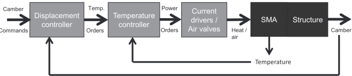
These sensors are used in two nested closed loops to control the camber. The reconstruct displacement is compared to a camber reference. Then a Proportional Integral (PI) controller send a SMA temperature reference to the temperature controllers. These controllers use temperature sensors information to give heating and cooling commands via PI controllers. The control architecture is summed up in Fig. 3.
Current
drivers /
Air valves Heat / air Orders Structure Camber Temperature Displacement controller Orders
Camber Temp. Power
Temperature
controller SMA
Commands
Fig. 4 : Camber control actuator
Experimental results
The previously described morphing wing has been characterized in a subsonic wind-tunnel. Experiments have been conducted at incidences up to 10[°], at Reynolds number relative to the chord up to 1,000,000. Pressure transducers are embedded in the wing. An aerodynamic balance measures drag and lift. More than 3,000 different morphing configurations have been investigated. The following section focuses on the actuators behavior during the experiments.
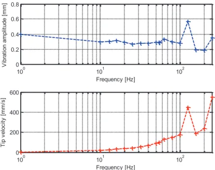
HFVTE in situ characterization. The HFVTE has been characterized in the wind-tunnel. A
planar laser beam is directed at the trailing edge that is filmed by a high speed camera. An image processing program extracts the laser-highlighted trailing edge position for every snapshot. For frequencies from 1[Hz] to 250[Hz] vibration Root Mean Square (RMS) displacements are extracted. The amplitude, shown in Fig. 5, is computed from the RMS displacement, reasonably assuming the displacement is sinusoidal.
(a) Trailing edge with surface embedded SMA (b) Reconstructed displacement VS measured
displacement 100 101 102 0 0.2 0.4 0.6 0.8 Frequency [Hz] V ib ra ti o n a m p lit u d e [ m m ] 100 101 102 0 200 400 600 Frequency [Hz] Ti p v e lo c it y [ m m /s ]
According to specifications explained in the previous section, amplitudes are relatively constant and greater than 0.3[mm] for frequencies up to 140[Hz]. This corresponds to trailing edge
displacements greater than 0.6[mm], even above 100[Hz] so the specifications are respected. As
the resonance amplitudes are large, tailoring resonance frequencies to the required actuation frequency can improve the vibration amplitude; but the bandwidth decreases. As a first experimental campaign, a large frequency bandwidth has been preferred to a large actuation amplitudes.
The first resonance mode found at 120[Hz] can be due a cover mode, as the amplitude keep rising continuously from 150[Hz] to 250[Hz], which can correspond to the first bending resonance mode.
Camber control performance. The camber control actuator has been intensively used during
wind-tunnel experiments. So its reliability has been tested. The maximum reachable camber decreased over time by nearly 15%. This issue is identified as SMA training. The SMA needs nearly 50 actuation cycles before performance stabilization. A maintenance is planned to reset the SMA pre-stress to retrieve nominal camber performance.
The performance of the nested-loops control is visible Fig 6(a). Rising the trailing edge displacement from 5[mm] to 7.5[mm] needs an increase of heating power to rise SMA temperature. The chosen control loops strategy produces an overshoot in displacement so the temperature is decreased to reach the reference displacement. This effect can be seen as a drawback according to control; but due to the SMA activation temperature hysteresis, the final required temperature to obtain trailing edge position when decreasing the displacement is lower than the temperature needed to obtain the same position when increasing the displacement. This effect is clearly visible on Fig. 6(b), where temperature is drawn depending on displacement for the same experiment as presented in Fig. 6(a). The calculation of the displacement maintaining heating power change due
to this decrease in needed temperature is evaluated at 20% to 30% reduction.
0 200 400 600 800 1000 1200 1400 1600 20 40 60 T e m p . [° C ] 0 500 1000 1500 0 20 40 60 Time (s) S M A p o w e r [W ] 0 200 400 600 800 1000 1200 1400 1600 -8 -6 -4 D is p la c e m e n t [m m ] Time (s) SMA 1 SMA 2 SMA 3 Reference measured (reconstructed) SMA 1 SMA 2 SMA 3 Reference Ambient -8 -7.5 -7 -6.5 -6 -5.5 -5 -4.5 30 35 40 45 50 55 60 Displacement [mm] Te m p e ra tu re [ °C ] SMA 1 SMA 2 SMA 3
Fig. 6: Camber actuator performance
(a) Temperatures, powers and displacement evolution during camber control.
(b) Temperature depending on trailing edge displacement.
Outlooks and conclusion
This article presents innovative actuators that respond to hybrid electroactive morphing specifications. As the state of the art focus on one component of morphing and material, the originality of the proposed approach is the combination of different actuations on airflow via different smart materials. The two actuators have been specified to reach a wide range of morphing, in order to investigate the effects in the wind-tunnel. Actuator behavior has been characterized and it has been shown that SMA control influences the power consumption.
Wind tunnel experiments have demonstrated the ability of the camber control to change the lift by 23%, the drag by 35% and the lift over drag ratio by 16%. In addition, the vibrating trailing edge is able to add some per cent gains to the achieve modifications by camber control.
The main objective of this study is to develop tools to design a true scale electroactive hybrid morphing flap. The next step is to post-process all the recorded data during wind-tunnel experiments.
References
[1] S Barbarino, E I Saavedra Flores, R M Ajaj, I Dayyani, and M I Friswell. A review on shape memory alloys with applications to morphing aircraft. Smart Materials and Structures, 23(6):063001, 2014.
[2] Silvestro Barbarino, Onur Bilgen, Rafic M Ajaj, Michael I Friswell, and Daniel J Inman. A review of morphing aircraft. Journal of Intelligent Material Systems and Structures, 22(9):823--877, 2011.
[3] M. Chinaud, J.F. Rouchon, E. Duhayon, J. Scheller, S. Cazin, M. Marchal, and M. Braza. Trailing-edge dynamics and morphing of a deformable flat plate at high reynolds number by time-resolved {PIV}. Journal of Fluids and Structures, 47:41 -- 54, 2014. Special Issue on Unsteady Separation in Fluid-Structure Interaction-l.
[4] Ignazio Dimino, Monica Ciminello, Antonio Concilio, Rosario Pecora, Francesco Amoroso, Marco Magnifico, Martin Schueller, Andre Gratias, Avner Volovick, and Lior Zivan. Smart In- telligent Aircraft Structures (SARISTU): Proceedings of the Final Project Conference, chapter Distributed Actuation and Control of a Morphing Wing Trailing Edge, pages 171--186. Springer International Publishing, Cham, 2016.
[5] Jaronie Mohd Jani, Martin Leary, Aleksandar Subic, and Mark A Gibson. A review of shape memory alloy research, applications and opportunities. Materials & Design, 56:1078--1113, 2014.
[6] Sridhar Kota, Peter Flick, and Fayette Collier. Flight testing of the FlexFoiltm adaptive compliant trailing edge. In 54th AIAA Aerospace Sciences Meeting, page 0036, 2016.
[7] Christian Lexcellent. Shape-memory alloys handbook. John Wiley & Sons, 2013.
[8] Zhoujie Lyu and Joaquim R. R. A. Martins. Aerodynamic shape optimization of an adaptive morphing trailing edge wing. Journal of Aircraft, 52:1951–1970, November 2015.
[9] Alexander M Pankonien, Cassio T Faria, and Daniel J Inman. Synergistic smart morphing aileron: Experimental quasi-static performance characterization. Journal of Intelligent Material Systems and Structures, 26(10):1179--1190, 2015.
[10] J. Scheller, M. Chinaud, JF. Rouchon, E. Duhayon, S. Cazin, M. Marchal, and M. Braza. Trailing-edge dynamics of a morphing {NACA0012} aileron at high reynolds number by high- speed {PIV}. Journal of Fluids and Structures, 55:42 -- 51, 2015.
[11] J. Scheller, G. Jodin, K. J. Rizzo, E. Duhayon, J. F. Rouchon, M. Triantafyllou, M. Braza, "A Combined Smart-Materials Approach for Next-Generation Airfoils", Solid State Phenomena, Vol. 251, pp. 106-112, 2016
[12] J. Scheller, K. J. Rizzo, G. Jodin, E. Duhayon, J. F. Rouchon, and M. Braza. A hybrid morphing NACA4412 airfoil concept. In Industrial Technology (ICIT), 2015 IEEE International Conference on, pages 1974--1978, March 2015.
[13] G. Jodin, J. Scheller, K. J. Rizzo, E. Duhayon, J. F. Rouchon, and M. Braza. Dimensionnement d'une maquette pour l'investigation du morphing électroactif hybride en soufflerie subsonique. Congrès Français de Mécanique, Online AFM, Association Française de Mécanique, 2015.