HAL Id: hal-01319221
https://hal.sorbonne-universite.fr/hal-01319221
Submitted on 25 May 2016
HAL is a multi-disciplinary open access
archive for the deposit and dissemination of
sci-entific research documents, whether they are
pub-lished or not. The documents may come from
teaching and research institutions in France or
abroad, or from public or private research centers.
L’archive ouverte pluridisciplinaire HAL, est
destinée au dépôt et à la diffusion de documents
scientifiques de niveau recherche, publiés ou non,
émanant des établissements d’enseignement et de
recherche français ou étrangers, des laboratoires
publics ou privés.
Diamond Dipole Antenna using a Hybrid Reflector
Chetan Joshi, Anne Claire Lepage, Julien Sarrazin, Xavier Begaud
To cite this version:
Chetan Joshi, Anne Claire Lepage, Julien Sarrazin, Xavier Begaud. Enhanced Broadside Gain of
an Ultra Wide Band Diamond Dipole Antenna using a Hybrid Reflector. IEEE Transactions on
Antennas and Propagation, Institute of Electrical and Electronics Engineers, 2016, 64 (7), pp.3269
-3274. �10.1109/TAP.2016.2565695�. �hal-01319221�
Abstract— This paper studies the effect of a hybrid reflector on
the radiation pattern of an ultra-wide band diamond dipole antenna. The cause of a split radiation pattern in the broadside direction appearing when using a uniform Artificial Magnetic Conductor (AMC) based reflector is investigated and is found to be due to destructive interference in broadside direction produced by surface currents localized in certain areas of the reflector. A hybrid reflector is then proposed to mitigate this problem by using both electrical and magnetic conductors. This solution enhances the gain in the broadside direction of the ultra-wide band antenna. A complete antenna with feeding system and hybrid reflector has been fabricated and measurement results are presented.
Index Terms— Artificial magnetic conductor (AMC), diamond
dipole antenna, hybrid reflector, low profile antenna, ultra-wide band antenna.
I. INTRODUCTION
ANTENNAS require being unidirectional for a variety of applications. For example, an antenna embedded on aircraft needs to radiate outside the aircraft, while preventing the electromagnetic contamination of its internal environment. To design these antennas, use of high impedance surfaces (HIS) as reflectors exhibit great advantages over conventional solutions like antennas with metallic reflectors. A reflector made up of perfect electrical conductor (PEC) needs to be placed at a distance of λ/4, λ being the wavelength at the central frequency of operation, in order to avoid the destructive interference between the incident and reflected electric fields in the broadside direction. This leads to a thick antenna profile. Metamaterials like HIS can be used instead to reduce the thickness of the antenna. Metamaterials are artificially engineered materials that exhibit exotic properties not found in natural materials. These properties originate from their structure and not from their composition.
An HIS is a planar structure with periodically repeating unit cell patterns. Such surfaces have properties that find use in designing reflector-backed antennas. Indeed, HIS behaves as an artificial magnetic conductor (AMC), as it exhibits an in-phase reflection between incident and reflected electric field [1]. Thus, reflectors designed using HIS may be placed in close proximity to the antenna without the destructive interference as
Manuscript received January 2016. This work is supported by the NanoDesign project funded by IDEX Paris-Saclay, ANR-11-IDEX-0003-02.
C. Joshi, A.C. Lepage and X. Begaud are with LTCI, CNRS, Télécom ParisTech, Université Paris-Saclay, 46 rue Barrault, 75634 Paris Cedex 13 (email: [email protected])
J. Sarrazin is with Sorbonne Universités, UPMC Univ Paris 06, UR2, L2E, F-75005, Paris, France (e-mail: [email protected])
seen earlier with PEC reflectors. This allows achieving a low-profile for the antenna.
AMC reflectors also present advantage of improved input impedance bandwidth. In [2], HIS surfaces with different types of unit cell patterns are investigated for use as reflectors for various monopole antennas. It is shown that input impedance bandwidths of the antennas are significantly enhanced when coupled with AMC reflectors. It is also insisted that full wave analysis of the proposed antenna in presence of AMC plane is necessary to correctly analyze the performance of the antenna.
In [3], it is shown that the input impedance, radiation pattern, and polarization characteristics of ground plane dependent antennas are influenced by both current distributions on the antenna as well as the induced current distribution on the finite PEC ground plane. It is further shown that broadside radiation pattern of a monopole antenna placed on the center of a finite ground plane appears to have more than one radiation lobe. This is attributed to the above-described currents circulating on the reflector surface. The use of HIS also poses similar challenges. In [4], TE surface wave resonances on the elements of HIS are studied and it is reported that they can be used to enhance the radiation of the dipole antenna. These resonances can be controlled by a variety of approaches.
One such approach to control contribution from AMC reflector is to change the size of the reflector to optimize the radiation. In [5], the effect of number and arrangement of elements in AMC under a dipole antenna has been investigated, and it is shown that there exists a certain configuration for unit cell arrangement on AMC, for which highest directive gain is obtained. In [6], it is reported that the radiation pattern of a dual dipole splits near the resonant frequency of the AMC. This problem is addressed by reducing the size of the AMC in the E-plane and by making it non periodic in the H-plane.
Use of hybrid reflectors, which are made up of more than one kind of unit cell, has also been investigated. In [7], dipole and patch antennas have been studied in proximity of a hybrid PEC-PMC reflector. Hybrid AMC-EBG (electromagnetic band gap) reflectors have also been reported in [8]. The EBG plane is a type of HIS with metallic vias that connect periodic patches to the ground plane. Use of such a hybrid reflector allows broadening radiation pattern in H-Plane of the dipole antenna by inhibiting propagation of surface waves in E-Plane.
Wide band dipoles in proximity to AMC reflector are an interesting case study. In [9], a wide band operation in a low profile dipole antenna is achieved using an EBG surface as a reflector. In [10], a printed bow-tie antenna with a wide band fractal AMC has been described. The antenna has a relative frequency bandwidth of 16.7% and it exhibits directive radiation patterns in E and H planes. The gain is enhanced by 4 dB. In [11], Best discusses design of broadband bow-tie dipole antenna placed in close proximity to the EBG plane. The antenna exhibits varying radiation patterns over its bandwidth. In the higher frequencies of the bandwidth, we observe a significant dip in the broadside direction and the radiation pattern thus appears to have split up. Such a defect can be a concern for wide band antenna applications like the one described in [12], which requires the dipole antenna to radiate in broadside direction. In [13], wide band diamond dipole antenna placed over EBG ground planes is discussed. The antenna and reflector plane are optimized together and the
Enhanced Broadside Gain of an Ultra-Wide
Band Diamond Dipole Antenna using a Hybrid
Reflector
Chetan Joshi, Anne Claire Lepage, Julien Sarrazin and Xavier Begaud
impedance bandwidth is reported to be 67%. Once again, the radiation degrades in the higher frequencies of bandwidth, with appearance of nulls in the broadside direction.
In this particular study, we discuss the challenge of designing a low profile diamond dipole antenna with an AMC reflector, which exhibits a high broadside gain over a large bandwidth. We study the reasons behind the split main lobe of radiation pattern, and consequently we propose a hybrid reflector to mitigate this problem. This paper is organized as follows. In Section II, the design of individual components of antenna i.e. diamond dipole, input feed, balun and AMC, is described. Then, also in Section II, the diamond dipole antenna and the AMC are studied together which leads to an optimum size of the AMC reflector. In Section III, problematic currents circulating on the AMC surface are identified and a novel hybrid reflector is proposed. In section IV the results of measurements carried out for a prototype are presented. Finally, conclusions of the study are drawn in Section V.
II. DESIGN METHODOLOGY
A. Antenna, Input feed and Balun
The diamond dipole antenna backed with an AMC plane has been previously studied in [13], where the difficulty to obtain the main lobe of the radiation pattern in broadside direction over the entire bandwidth of operation has been reported. In the present study, the diamond dipole antenna is printed on a CuClad substrate with thickness hCuClad = 1.58 mm, relative
permittivity εCuClad = 2.5, and loss tangent tan δCuClad = 0.0018.
The dimensions of the antenna are given in Fig. 1(a) and Table I. Final size of antenna substrate depends upon the size of AMC reflector, which is discussed later in Section II.C. From simulation performed with CST Microwave Studio (Transient solver) using a 100 Ω discrete port, the antenna bandwidth was found to be 53% (4.56-7.84 GHz), taking the criterion of |S11| <
-10 dB.
Due to the stacked nature of the antenna with AMC reflector, it is proposed to feed the antenna with a 50 Ω SMA connector placed at the edge of the antenna substrate. Coplanar Stripline (CPS) with a characteristic impedance, Zc = 100 Ω is printed on
the back face of the antenna substrate. The dimensions of the CPS line structure as shown in Fig. 1 (b) are wCPS = 2.4 mm and
gCPS = 0.22 mm. A balun is then used to achieve the transition
from 50 Ω coaxial connector to 100 Ω coplanar line as explained below.
The central pin of the 50 Ω coaxial connector is connected to a 50 Ω microstrip line. This microstrip line is then connected to the first transmission line of 100 Ω CPS structure. The second transmission line of CPS is connected to the ground of the coaxial connector using seven transition-via, as shown in Fig. 1(b). Radius of transition via is rTr = 0.2 mm, and they are
separated by a distance equal to 2*rTr. It is noted that using the
back to back transition technique, the balun is found to be matched (|S11| < -10 dB) in the range 2.1 – 6.8 GHz, with a
secondary band in 7.4 – 8 GHz. This balun structure is inspired from wide band baluns discussed in [14].
The length of CPS is fixed according to the size of the
reflector, which is discussed later in Section II.C. On the other end, the CPS Line is connected to the antenna using a twin-line-like structure comprising two parallel metallic via, each one connected to one arm of the diamond dipole through the antenna substrate. The radius of via is rVia = 0.4 mm and
they are separated by a distance d = 1.25 mm measured at the center.
On simulating the antenna with the feeding circuit without the AMC reflector, a primary band of 26% (4.5 – 5.8 GHz) is obtained with resonance at 5.15 GHz. A secondary band in the range 6.9 – 8.2 GHz is also observed. In the next sub-section, the design of AMC reflector is described.
B. Design of AMC
The AMC is an array of square copper patches printed on a substrate backed by a metallic ground plane. It should be noted that as only AMC property is sought in our design, no via are used to connect the metallic patches to the underlying ground plane (no EBG behavior is therefore achieved). The AMC has zero phase of its reflection coefficient in the operation bandwidth of the wide band dipole. The AMC is designed with FR4 Epoxy substrate with εFR4 = 4.0, tan δFR4 = 0.02, and a
thickness of hFR4 = 3.2 mm. Simulations done with CST
Microwave Studio have been performed on a unit cell under appropriate boundary conditions, as discussed in [15], in order to emulate an infinite lattice of periodically arranged unit cells. The dimensions of AMC are found out to be wAMC = 7.4 mm,
gAMC = 1 mm, where w denotes the width of the patch and g
denotes the gap between the patches. The frequency at which the in-phase reflection is observed is f0 = 5 GHz.
Therefore at f0, the AMC surface behaves as a perfect
magnetic conductor. The phase interval of reflection coefficient leading to constructive interference in antenna plane (-90°, +90°) is from 4.2 to 5.8 GHz (32%). It is noted that this frequency band covers the primary bandwidth of the antenna with input feed, as reported in the end of Section A.
Fig. 1. (a) Diamond dipole antenna. (b) Balun Structure TABLEI
DIMENSIONS OF THE DIAMOND DIPOLE
Parameter Value (in mm)
L 9.0
S 0.3
a 1.5
The unit cell characterized in this section is now used to design an AMC of finite size by arranging these unit cells in a 2-D square lattice. The bandwidth of the whole antenna varies with the size of AMC. This is further investigated in sub-section C.
C. Diamond Dipole over AMC
In this section, we analyze performance of the antenna when placed over an AMC designed using unit cell of the previous section. For this purpose, simulations are carried out in CST Microwave Studio to find optimal design parameters. The distance between antenna and AMC plane is studied first. Thereafter, the effect of size of AMC reflector on the antenna bandwidth and gain is reported. For faster simulations, the antenna was fed using a discrete port at the input.
It may be recalled here that an incident plane wave has been considered to characterize the unit cell of AMC, whereas in the present scenario, the AMC is located in the near-field of the antenna. A numerical optimization step is therefore necessary. For this purpose, the distance between the antenna and the AMC is optimized to achieve a good impedance matching. On simulating with CST Microwave Studio, the optimum distance is found out to be hair = 2 mm. hair is chosen so as keeping the
whole antenna matched in the operating frequency band as well as maintaining constructive interference in broadside direction. The overall thickness of the radiating structure becomes 6.78 mm, which is 0.11λ at 5 GHz.
The performance of the final structure depends also upon the size of AMC. Various sizes of AMC reflector have been studied: 6x6, 8x8, 10x10, and 12x12 cells. It is noted that a trade-off exists between bandwidth of the antenna, gain in broadside direction and size of the AMC reflector, as can be deduced from Fig. 2. The lower frequency in the bandwidth for all sizes of AMC reflector is about 4.25 GHz. But the upper frequency of the bandwidth shifts higher as the number of patches in the reflector increases. Increasing the number of patches in the AMC increases the bandwidth of the entire structure. For an AMC reflector with 6x6 cells the highest frequency of the impedance bandwidth is 5.65 GHz, whereas for a configuration of the reflector with 12x12 cells the highest frequency in the impedance bandwidth reaches 7.16 GHz. This is due to the fact that more resonances can be supported by the AMC when the number of patches increases. It is also seen in Fig. 2 that the broadside gain is higher for an antenna backed
with smaller 6x6 AMC reflector. As the size of reflector increases, the broadside gain fluctuates more across the bandwidth. It may be noted here that simulations using balun to feed the antenna also exhibit similar fluctuation in realized gain of antenna, but take longer time to complete.
Finally, an AMC with 8x8 cells is chosen as the reflector for the current study, represented by solid line in Fig. 2. It provides an optimal trade-off between bandwidth and size, but the problem of fluctuation in broadside gain needs to be solved for an optimal solution. The dimension of this 8x8 square AMC is 67.2 mm x 67.2 mm and the ground plane underneath the AMC patches is 75 mm x 75 mm. The size of the antenna substrate is chosen larger than the reflector substrate i.e. 88 mm x 75 mm. This allows the balun to be just outside AMC. When this antenna is backed with the above-described 8X8 AMC array, the primary band obtained with the structure is 40% (4.15-6.24 GHz). Other bands appear in frequencies ranging from 6.8 to 8.1 GHz.
III. HYBRID REFLECTOR:BEAM SPLITTING CANCELLATION
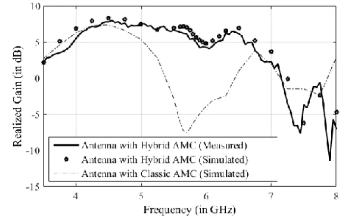
In this section, results of simulations carried out on the antenna with the balun backed with uniform and hybrid AMC are discussed. As explained in Section I, using an AMC reflector can enhance the gain of the antenna. The surface currents on the AMC reflector play a role in increasing the broadside gain. To investigate further the radiation of the diamond dipole antenna backed by the 8x8 AMC reflector designed in Section II, its broadside gain is studied over the impedance-matched bandwidth. Fig. 13 presented later in the article plots the realized gain of antenna in broadside (Theta = 0°, Phi = 0°) versus frequency. As shown by the dash-dotted trace in Fig. 13, the antenna with uniform reflector has a peak gain of 7.4 dB at 4.6 GHz. But it is also observed that at 5.8 GHz, there is a substantial dip in gain in the broadside direction (-6.2 dB). The realized gain is less than 0 dB from 5.4 GHz to 6.4 GHz. This causes a blind spot in the broadside in middle of the bandwidth.
The beam splitting is a problem for an antenna system that is to be used for its broadside radiation characteristics. The reason behind this behavior is perceived to be the presence of surface currents on the AMC that cause destructive interference and lead to loss of gain in broadside radiation pattern at 5.8 GHz. To further investigate this phenomenon, a study of the surface currents on AMC is done using the method introduced in [16].
Unlike the dipole antenna where the current is highly localized within a small surface, currents on AMC are spread over a larger surface. At 5.8 GHz, some currents present on AMC surface circulate such that their contribution to the gain in the broadside is destructive, resulting in a null in radiation pattern. These can be identified by studying the phases of surface current density on the reflector at 5.8 GHz.
Since the antenna is polarized in the E-plane (along the x-axis), only the current density Jx contributing to this
polarization is considered. The radiation of the antenna is mostly due to the contribution of higher Jx current amplitudes.
It is arbitrarily assumed that all currents whose amplitude is superior to 0.5 Jx max constitute the strongest currents circulating Fig. 2. Comparison of S11 and realized gain of the diamond dipole antenna fed
on reflector surface. The constructive phase interval is hence defined as (ϕx min - 90°, ϕx max + 90°), where ϕx min and ϕx max are
the phases of weakest and strongest amplitudes in the above-defined set of strongest currents. The remaining currents are said to circulate in a destructive phase interval. Then currents on the reflector whose phase is in destructive interval are plotted on the reflector.
Here, the contribution of Jx is studied by plotting Hy, which is
the y-component of magnetic field on surface of AMC. The destructive phase interval in this particular case is found to be (-30°, 70°). Thus any current whose phase lies within this range contributes to the destructive interference in the broadside direction. Fig. 3 identifies the strongest destructive phase, which is set of phases of all destructive currents greater than 0.25 times the highest amplitude of destructive currents. The negative phase values have been readjusted in the 0°- 360° range.
It is clearly seen that the currents with destructive contribution are located in various parts of AMC. The strongest amplitude is observed in the two extreme rows in the y-axis, as shown in Fig. 3. Resonances in the two rows of patches allow the concentration of current circulating in destructive phase interval. If the surface of AMC reflector is changed in these two rows, then it changes the distribution of currents with destructive contribution in the radiation pattern. Using a PEC strip allows avoiding the aforementioned resonances. This new structure is simulated.
In Fig. 4, phase of the problematic currents on the hybrid AMC has been plotted. Same approach to study surface
currents has been adopted as in case of uniform AMC. The destructive phase interval in this case is (307°, 347°). It is observed here that the range of destructive phase is small. Secondly, the corresponding amplitudes of the currents in this destructive phase range are not very significant and their contribution to the broadside radiation pattern is therefore negligible.
Fig. 5 compares the magnitude of reflection coefficient from simulated and measured performances of the antenna. As seen in the dotted line, the simulated impedance bandwidth of this antenna is 2.8 GHz (4.1-6.2 GHz) with a secondary band between 7.2-8.1 GHz. A significant improvement is also observed in the realized gain of the antenna at 5.8 GHz, as shown in Fig. 13 by marker trace. The gain in broadside direction is now 6.1 dB. It should be noted in Fig. 13 that the hybrid reflector only corrects the fault around 5.8 GHz, and it behaves similarly to the uniform reflector in higher frequencies. The reasons stated above explain the improved gain in the broadside direction. The above-described method could be used to optimize the broadside radiation of other types of antennas showing similar kind of behavior.
Since the above solution contains both electrical and magnetic conductors, it is referred henceforth as a hybrid reflector. The final configuration of the fabricated antenna and hybrid reflector assembly is shown in Fig. 6. Its performance is discussed in the next section.
Fig. 3. Phase plot (in degrees) of problematic current on the uniform AMC.
Fig. 4. Phase plot (in degrees) of problematic current on the hybrid AMC.
Fig. 6. Final antenna with hybrid reflector.
Fig. 5. Simulated and measured magnitudes of S11 for diamond dipole on
IV. REALIZATION
The antenna and the hybrid reflector are fabricated with the dimensions as defined in previous sections. In order to stack the antenna over the reflector, four holes are drilled on the corners of the antenna and reflector substrates. Using two plastic washers on each corner ensures the separation between the antenna and the reflector corresponding to hair. Thickness of the
washers is 1 mm each. A 50 Ω SMA connector is soldered to the balun. The measurements are done in an anechoic chamber.
The measured |S11| result is presented in Fig. 5 by the solid
line. It is observed that the fabricated antenna is better matched in impedance than the simulated antenna. The measured bandwidth at |S11| < -10 dB is 3.9 GHz (4.2 - 8.1 GHz).
Assuming the center frequency as 6.15 GHz, the bandwidth becomes 63%. It may also be noted that the final antenna assembly’s bandwidth exceeds the bandwidth of both the antenna and AMC individually.
Fig. 7-12 show the comparison between the simulated and measured far field radiation patterns at 4, 5 and 6 GHz respectively. Realized gain of the antenna is measured in the E & H Planes to verify the broadside radiation characteristics for different frequencies. The solid line in Fig. 13 plots the measured gain of the antenna in the broadside direction over the matched bandwidth. The simulated and measured results are in close agreement with each other.
On comparing the realized gain of the antenna with uniform and hybrid reflectors, it is seen that the problem of dip in broadside gain has been resolved by using PEC strips at the identified location in the structure of AMC, thus allowing high broadside gain in the entire bandwidth. An improvement of 12.3 dB in broadside gain is observed at 5.8 GHz. Maximum gain in the bandwidth is Gmax = 7.9 dB at 4.5 GHz. It is also
verified that changing this structure in the above described way does not lower the broadside gain for the lower frequencies in the band. At 8 GHz, a minimum is observed in the radiation
Fig. 7. Realized gain in E-plane at 4 GHz.
Fig. 8. Realized gain in E-plane at 5 GHz.
Fig. 10. Realized gain in H-plane at 4 GHz.
Fig. 9. Realized gain in E-plane at 6 GHz.
Fig. 11. Realized gain in H-plane at 5 GHz.
pattern. Therefore this frequency can be excluded from the operational bandwidth of the antenna when considering broadside gain. Simulations and measurements are in close agreement with each other. If the usable bandwidth of the antenna is defined as |S11| less than -10 dB and realized gain in
broadside greater than (Gmax - 3 dB), then the antenna has a
usable bandwidth of approximately 46% (4.2 - 6.7 GHz). The antenna maintains low levels of cross polarization in the broadside direction inside the usable bandwidth. The Front-to-Back ratio of the antenna with hybrid reflector is also found to have considerably improved and is greater than 16 dB in the usable bandwidth.
V. CONCLUSION
In this work a wide band antenna backed with a hybrid reflector has been introduced. The thickness of the overall structure is in the order of λ/10 at the center frequency of operation, i.e. 5.45 GHz. The hybrid reflector uses both electric and magnetic conductors to achieve a wide band antenna exhibiting a maximum gain in the broadside direction. In order to design this structure, an AMC-backed wide band dipole antenna is first proposed. The radiation patterns at various frequencies are studied and the phenomenon of beam splitting and consequently loss of gain in broadside direction is reported at some particular frequencies in the impedance bandwidth. The beam splitting is attributed to presence of surface currents circulating in a phase interval that leads to destructive interference in the broadside direction. A method is used to identify the location of these currents on the AMC surface. To solve the beam splitting problem, the structure of reflector is modified locally by combining both electric and magnetic conductors. Thanks to this approach, the beam splitting effect canceled and the frequency band in which the antenna exhibits directive gain is in the broadside direction has been increased. The hybrid reflector-based antenna has been fabricated. The prototype has a matched-impedance bandwidth of 63% about 6.19 GHz and by considering a 3 dB fluctuation criteria on the desired gain in the broadside direction, the usable bandwidth of the antenna is found out to be 46%. Measurements of radiation pattern are found to be in fair agreement with the simulations.
REFERENCES
[1] D. Sievenpiper, L. Zhang, R.F.J. Broas, N.G. Alexopolous, and E. Yablonovitch, "High-impedance electromagnetic surfaces with a forbidden frequency band," IEEE Trans. Antennas Propagat., vol. 47, no. 11, pp. 2059-2074, 1999.
[2] A. Foroozesh and L. Shafai, "Investigation into the application of artificial magnetic conductors to bandwidth broadening, gain enhancement and beam shaping of low profile and conventional monopole antenna," IEEE Trans. Antennas Propagat., vol. 59, no. 1, pp. 4-20, Jan 2011.
[3] S.R. Best, "The significance of ground-plane size and antenna location in establishing the performance of ground-plane-dependent antennas,"
Antennas and Propagat. Mag., IEEE, vol. 51, no. 6, pp. 29-43, Dec 2009.
[4] F. Costa, O. Luukkonen, C.R. Simovski, A. Monorchio, S.A. Tretyakov, and P.M. de Maagt, "TE surface waves on a high-impedance surface based antennas: Analysis and modelling," IEEE Trans. Antennas
Propagat., vol. 59, no. 10, pp. 3588-3596, Oct 2011.
[5] Y. Murakami, T. Hori, and M. Fujimoto, "Optimum reflector configuration for dipole antenna by using artificial magnetic conductor," in Internat. Workshop Anten. Techn. (iWAT), 2013, pp. 277-280. [6] R.M. Mateos, C. Craeye, and G. Toso, "High-gain wide band low-profile
antenna," Microw. and Optical Tech. Lett, vol. 48, no. 12, pp. 2615-2619, 2006.
[7] A. Foroozesh and L. Shafai, "Application of combined electric and magnetic conductor ground planes for antenna performance enhancement," Canadian Journ. Electr. and Comput. Engg., vol. 33, no. 2, pp. 87-98, Spring 2008.
[8] L.M. Abdelghani, T.A. Denidni, and M. Niroo-Jazi, "Antenna beam shaping using conformal hybrid AMC/EBG reflectors," in Anten. and
Propagat. Soc. Internat. Sym. (APSURSI), July 2014, pp. 1770-1771.
[9] M.Z. Azad and M. Ali, "Novel wide band directional dipole antenna on a mushroom like EBG structure," IEEE Trans. Antennas Propagat., vol. 56 , no. 5, pp. 1242-1250, May 2008.
[10] Y.W. Zhong, G.M Yang, and L.R. Zhong, "Gain enhancement of bow-tie antenna using fractal wide band artificial magnetic conductor ground,"
Electron. Lett., vol. 51, no. 4, pp. 315-317, Feb 2015.
[11] S.R. Best and D.L. Hanna, "Design of a broadband dipole in close proximity to an EBG ground plane," Antennas and Propagation
Magazine, IEEE , vol.50, no.6, pp. 52-64, Dec. 2008.
[12] G. Li, H. Zhai, L. Li, C. Liang, R. Yu, and S. Liu, "AMC-loaded wide band base station antenna for indoor access point in MIMO system,"
IEEE Trans. Antennas Propagat., vol. 63, no.2, pp. 525-533, Feb. 2015.
[13] L. Akhoondzadeh-Asl, D.J. Kern, P.S. Hall, and D.H. Werner, "Wide band dipoles on electromagnetic bandgap ground planes," IEEE Trans.
Antennas Propagat., vol. 55, no. 9, pp. 2426-2434, Sept 2007.
[14] Y.G. Kim, D.S. Woo, K.W. Kim, and Y.K. Cho, "Design of bow-tie-type UWB antennas using an ultra-wide band balun," in Anten. and Propagat.
Soc. Int. Symp., 2007 IEEE, pp.1989-1992, 9-15 June 2007.
[15] F. Yang and Y. Rahmat-Samii, "Reflection phase characterizations of the EBG ground plane for low profile wire antenna applications," IEEE
Trans. Antennas Propagat., vol. 51, no. 10, pp. 2691-2703, Oct 2003.
[16] A. C. Lepage, J. Sarrazin, and X. Begaud, "Wide band Directive Antennas with High Impedance Surfaces," in Microwave and Millimeter Wave
Circuits and Systems, John Wiley & Sons,Ltd., 2013, pp. 69-73.