HAL Id: hal-02916195
https://hal.archives-ouvertes.fr/hal-02916195
Submitted on 17 Aug 2020
HAL is a multi-disciplinary open access
archive for the deposit and dissemination of
sci-entific research documents, whether they are
pub-lished or not. The documents may come from
teaching and research institutions in France or
abroad, or from public or private research centers.
L’archive ouverte pluridisciplinaire HAL, est
destinée au dépôt et à la diffusion de documents
scientifiques de niveau recherche, publiés ou non,
émanant des établissements d’enseignement et de
recherche français ou étrangers, des laboratoires
publics ou privés.
Comprehensive frequency chirp characterization of
silicon ring resonator modulators
Erwan Weckenmann, Laurent Bramerie, Mathilde Gay, Diego Pérez-Galacho,
Frédéric Boeuf, Lucas Deniel, Delphine Marris-Morini, Christophe Peucheret
To cite this version:
Erwan Weckenmann, Laurent Bramerie, Mathilde Gay, Diego Pérez-Galacho, Frédéric Boeuf, et al..
Comprehensive frequency chirp characterization of silicon ring resonator modulators. OSA Advanced
Photonics Congress 2020 (APC 2020), The Optical Society, Jul 2020, Washington, United States.
pp.ITu1A.4, �10.1364/IPRSN.2020.ITu1A.4�. �hal-02916195�
Comprehensive frequency chirp characterization of silicon
ring resonator modulators
E. Weckenmann1, L. Bramerie1, M. Gay1, D. Pérez-Galacho2,3, F. Boeuf4, L. Deniel2, D. Marris-Morini2, and
C. Peucheret1
1- Univ Rennes, CNRS, FOTON – UMR 6082, F-22305 Lannion, France
2- Université Paris-Saclay, CNRS, Centre de Nanosciences et de Nanotechnologies, 91120 Palaiseau, France 3- Now at ITEAM Research Institute, Universitat Politècnica de València, Camino de Vera s/n, 46022 Valencia, Spain
4- ST Microelectronics, 850 rue Jean Monnet, 38920 Crolles, France erwan.weckenmann@univ-rennes1.fr
Abstract: The frequency chirping properties of a silicon ring resonator modulator are
experimentally investigated and compared to a numerical model. The influence of the wavelength detuning and the modulation frequency are highlighted for the first time. © 2020 The Author(s)
1. Introduction
Silicon ring resonator modulators (RRMs) are promising devices for short-distance optical communication systems thanks to their compactness, energy efficiency and low cost. Their resonant nature enables highly-efficient intensity modulation (IM) [1]. Short-distance systems based on direct-detection, such as the inter data center links that are the objects of significant interest at the present time, can reach transmission lengths exceeding 80 km over standard single-mode fibers that are dispersive at 1.5 m. The frequency chirping properties of RRMs are therefore of paramount importance for such applications. However, they have been to date the object of only a few numerical studies. The chirp parameter of silicon RRMs has been evaluated thanks to numerical models based on the applied voltage-induced variations of the transmission and phase of micro-resonator transfer functions calculated using either the temporal coupled-mode theory [2] or a scattering matrix approach [3]. The dependence of the chirp on the modulation frequency and on the laser-resonance detuning has however not been fully assessed. Some preliminary experimental characterizations based on measurements of the instantaneous variations of the frequency in an interferometer have been presented in [4]. The impact of the frequency chirp could also be observed from measurements of the small-signal frequency responses of dispersive direct-detection channels [3,4].
In this paper, we experimentally investigate the chirping properties of a silicon RRM by measuring the variations of the amplitude and phase of the electric field at its output using a coherent detection technique, which allows us to collect time-resolved data. The measurements are made in the small-signal regime for different wavelength detunings between the laser and the resonance, and as a function of the modulation frequency. The chirp parameter extracted from experimental data is studied and compared to the results of an analytical model, which shows a good agreement. Furthermore, the influence of the wavelength detuning as well as of the modulation frequency on the RRM time-dependent chirp parameter are shown for the first time.
2. Results and discussion
The silicon RRM studied in this work was designed by C2N and fabricated by ST Microelectronics. The ring has a radius of R = 20 µm and its waveguide is doped to form a PN junction in order to exploit carrier depletion to induce a phase-shift when a voltage is applied [5]. An analytical dynamic model based on [6] is used to calculate the electric field at the output of the RRM under small-signal modulation. The model parameters of the micro-ring are chosen to
fit the static transfer function of the RRM measured in the absence of applied voltage, which has a Q-factor of 3104.
A continuous wave from a tunable laser source is modulated by the RRM with small-signal sinusoidal voltage signals with different modulation frequencies. The source wavelength ( ) is tuned with respect to the resonance
wavelength ( ) according to a detuning value ∆ = − . The modulated optical wave is then input to a heterodyne
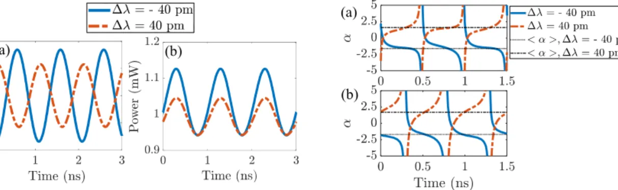
coherent detection system to recover the full electric field after some digital processing, from which the frequency chirp can be calculated. Figure 1 shows typical examples of the measured frequency chirp as a function of time, noted ∆ ( ), and the corresponding power waveforms for opposite wavelength detunings. In order to compare the frequency chirp waveforms for detunings of ∆ = +40 pm and ∆ = −40 pm in Fig. 1(a), it is ensured that the corresponding power waveforms are temporally aligned (Fig. 1(b)). A π phase difference is observed between the frequency chirp waveforms measured for symmetric detuning values. The frequency-chirp of optical modulators is commonly
described by the parameter, which links the frequency modulation to the IM according to = 2 ∆ ( )/ ,
where is the modulated power. Figure 2 shows the simulated and measured chirp parameter as a function of time for opposite wavelength detuning values and a modulation frequency of 1 GHz. It can be seen that the chirp parameter
is increasing for a positive detuning while it is decreasing with an opposite slope for negative detuning. Opposite parameters result in opposite frequency chirp values, which indeed correspond to π shifts for sinusoidal waves.
Figure 3 represents the measured and simulated phase-shifts between the IM and FM signals as a function of modulation frequency for different values of positive and negative detunings. A π phase-shift is observed between the FM waveforms measured for the same absolute value of positive or negative detuning once the IM waveforms have been temporally aligned. This behavior is also in good agreement with the analytical model.
This detuning dependence on the RRM chirp has already been suggested in [2], where a constant parameter defined from calculated static transfer functions was considered. The time-dependent parameter that is studied here confirms this behavior. Moreover, the dependence of the chirp parameter on the modulation frequency can be investigated. Figure 4 shows the mean values of the chirp parameter, noted < ( )>, as a function of modulation frequency. Besides the impact of the wavelength detuning, a dependence on the modulation frequency that is typical of this kind of modulator is clearly seen. This last observation emphasizes the fact that the exploitation of the frequency chirping properties of silicon RRMs (as e.g. in [4]) must depend on the used modulation frequency range.
In conclusion, the frequency chirping properties of silicon RRMs have been experimentally characterized and their dependence on the wavelength detuning and the modulation frequency is highlighted. A good agreement with an analytical model is shown, which should ease the chirp optimization for high-speed communication applications.
3. References
[1] J. Witzens, “High-speed silicon photonics modulators,” Proc. IEEE 106, 2158 (2018).
[2] Z. Wang et al., “Silicon microring modulator for dispersion uncompensated transmission applications,” J. Lightw. Technol. 34, 3675 (2016). [3] O. Dubray et al., “Simulation and measurements of chirp penalties for silicon ring resonator modulators,” IEEE Photon. Technol. Lett. 28, 280 (2016).
[4] M. Chaibi et al., “Multiple-band OFDM transmission exploiting the frequency chirping properties of silicon ring-resonator modulators,” in
Asia Communications and Photonics Conference, (Optical Society of America, 2017), paper M2G.1.
[5] D. Marris-Morini et al., “A 40 Gbit/s optical link on a 300-mm silicon platform,” Opt. Express 22, 6674 (2013). [6] W. D. Sacher and J. K. S. Poon, “Dynamics of microring resonator modulators,” Opt. Express 16, 15741 (2008).
Fig. 2. (a) Simulated and (b) measured chirp parameter as a function of time at a modulation frequency of 1 GHz for
opposite wavelength detunings. < > is the mean value. Fig. 1. Measured (a) frequency chirp and (b) power (normalized)
as a function of time at a modulation frequency of 1 GHz for wavelength detunings of +40 pm and -40 pm.
Fig. 3. Measured (points) and simulated (lines) phase-shifts between IM and FM as a function of modulation frequency for
different wavelength detunings.
Fig. 4. Measured and simulated mean values of the chirp parameter as a function of the modulation frequency for
different wavelength detunings.
(a) (b)
(a)