HAL Id: hal-00497263
https://hal.archives-ouvertes.fr/hal-00497263
Submitted on 3 Jul 2010
HAL is a multi-disciplinary open access archive for the deposit and dissemination of sci-entific research documents, whether they are pub-lished or not. The documents may come from teaching and research institutions in France or abroad, or from public or private research centers.
L’archive ouverte pluridisciplinaire HAL, est destinée au dépôt et à la diffusion de documents scientifiques de niveau recherche, publiés ou non, émanant des établissements d’enseignement et de recherche français ou étrangers, des laboratoires publics ou privés.
Alexandre Garreau, Olivier Vaudel, Christophe Kazmierski, Guang-Hua
Duan, Jean-Claude Simon
To cite this version:
Quoc Thai Nguyen, Pascal Besnard, Laurent Bramerie, Alexandre Shen, Alexandre Garreau, et al.. Using optical injection of Fabry-Perot lasers for high-speed access in optical telecommunications. SPIE Photonics Europe 2010, Apr 2010, Bruxelles, Belgium. pp.77202D, �10.1117/12.855133�. �hal-00497263�
Using optical injection of Fabry-Perot lasers for high-speed access in
optical telecommunications
Quoc Thai Nguyen
a, Pascal Besnard
a, Laurent Bramerie
a, Alexandre Shen
b, Alexandre Garreau
b,
Olivier Vaudel
a, Christophe Kazmierski
b, Guang-Hua Duan
b, Jean-Claude Simon
aa
Lab. CNRS/FOTON-ENSSAT, Université de Rennes 1, 6 rue de Kerampont, Lannion, France;
bAlcatel-Thales III-V Lab, a joint laboratory of “Alcatel-Lucent Bell Labs France” and “Thales
Research and Technology”, Route de Nozay, 91460 Marcoussis, France
quocthai.nguyen@enssat.fr
ABSTRACT
In this paper we present our recent works on optical injection of Fabry-Perot laser diode for application in access networks. The injection-locked Fabry-Perot laser diode is used as low-cost colorless transmitters for high-speed optical access exploiting wavelength-division-multiplexing technology. The modification of main characteristics of Fabry-Perot laser such as spectral properties, noise and modulation is shown in injection-locking regime. The strong dependence of these properties onto injection parameters is also given. Finally, the operation of injection-locked Fabry-Perot laser diode in a wavelength-division-multiplexed optical access system using a novel multi-wavelength master source based on quantum-dash mode-locked laser is presented and its transmission performances at 2.5 Gb/s are reported.
Keywords: Injection-Locked Fabry-Perot laser diode, wavelength-locking, wavelength-division-multiplexing, colorless
operation, optical access networks, quantum-dash mode-locked laser, semiconductor lasers.
1. INTRODUCTION
Injection-locking in a semiconductor laser is based on the fact that the laser can be locked to frequency and phase of an external injected optical signal [1]. This physical phenomenon is very attractive thanks to its broad applications such as millimeter-wave generation, wavelength conversion, clock recovery, etc…When a Fabry-Perot laser diode is locked onto a single-mode signal, its operation become single-mode at the same frequency that the one of the injected signal. This characteristic is extremely interesting for wavelength-division-multiplexed (WDM) optical access networks [2]. The optical access network links the operator’s head-end called the Central Office to the optical network terminals via the Passive Remote Node, as shown in figure 1. The access network using WDM technology dedicates a specific wavelength to each network terminals. However, the operation of such network requires a simplified WDM resource management. To meet this requirement, identical transmitters (so-called colorless transmitters) are needed in order to avoid the inventory problem. For this issue, injection-locked Fabry-Perot laser diode (IL-FP) presents a promising solution [2]. In such applications, the Fabry-Perot laser diodes (FP-LD) act as colorless transmitters, which are wavelength-controlled via injection-locking with master sources centralized at the Central Office.
Related to this concept, FP-LD injection-locked by an incoherent signal based on spectrally-sliced broadband light source (BLS) has been proposed as a low-cost colorless transmitter for WDM access [3]. The BLS may include amplified spontaneous emission (ASE) sources or super-continuum (SC) sources. This proposal is attractive due to its low-cost and simple implementation. On the other side, since the BLS-based master sources inherently suffers from high intensity noise, the speed of BLS-injected FP LD is typically limited to 1.25 Gb/s [4]. However, with the needs of ever-increasing bandwidth in access networks, this data rate seems to be insufficient in the next future. To avoid this limitation related to high intensity-noise of incoherent injection source, we recently proposed a novel multi-wavelength injection sources, based on quantum-dash mode-locked-lasers [5]. This injection source is more advantageous compared to incoherent sources, in terms of intensity-noise and coherency, while maintaining the cost-effectiveness for access networks.
7720 - 83 V. 1 (p.1 of 10) / Color: No / Format: A4 / Date: 2010-04-12 11:15:58 AM
Figure 1: Optical access network using WDM technology
In this paper, the characterization of a FP-LD injection-locked by a reference single-mode master laser is firstly presented. The dependence of spectral properties, relative intensity noises (RIN), small-signal responses and linewidth enhancement factor of IL-FP onto injected signal is shown. The performance of directly modulated 2.5 Gb/s IL-FP is then assessed. The impact of injection parameters on performance of IL-FP is also discussed. Finally, the operation of IL-FP in a WDM access configuration is described and its performances are addressed.
2. CHARACTERIZATION OF INJECTION-LOCKED FABRY-PEROT LASER
2.1 Spectral propertiesOptical injection in a single-mode laser is well known with the appearance of many dynamical regimes such as locking, wave-mixing, relaxation and chaos [6]. In case of optical injection in a FP-LD for application in WDM access, only wavelength-locking regime is desired. For this reason, the FP-LD used for injection is frequently polarized at a low current in order that the locking bandwidth is maximized and to avoid complex regimes like wave-mixing and chaos [7]. In order to determine in which conditions (optical power, wavelength of the injected signal) the FP-LD is locked, it is essential to map the operating regimes on a chart defined by the two parameters, injected power and detuning which corresponds to the difference between the wavelengths of the injected signal and the one of a specific mode of FP-LD that is submitted to optical injection. It is so-called injection map, which is well known for a single-mode laser [6].
Figure 2: Optical spectra of FP-LD (a) and static injection map of FP-LD for a specific mode at 1555 nm
Figure 2 (a) shows an example of optical spectra of FP-LD in free-running regime and in locking regime when injected by a single-mode signal of -10 dBm at the borders of the C-band (1530 nm and 1565 nm). In the locking regime, the
(a)
(b)
7720 - 83 V. 1 (p.2 of 10) / Color: No / Format: A4 / Date: 2010-04-12 11:15:58 AM
mode submitted to optical injection is locked to the wavelength of master laser while the other modes are strongly attenuated. Thus, a side mode suppression ratio (SMSR) higher than 30 dB is obtained, the operation of IL-FP can be considered as single-mode. The static injection map of FP-LD is given in figure 2 (b). Since the FP-LD under study has an important number of modes crossing the C-band, the injection map of only one mode at 1555 nm is shown. The blue region corresponds to the locking regime. We can see that this last regime starts with an injected power of -16 dBm at zero detuning. The spectral range of locking regime increases with injected power. With an injected power higher than -5 dBm, the spectral range of locking region covers the free spectral range (FSR) of FP-LD, i.e. the FP-LD is locked whatever injected wavelength within this specific mode. The white region corresponds to un-locking regime. In this regime, the output signal of FP-LD is simply a sum of two signals (free-running FP-LD and injected signal) or corresponds to a weak locking regime with a SMSR < 30 dB. To evaluate the injection-locking efficiency over the full spectral range of FP-LD, we vary the wavelength of the master laser in order to inject into each mode within the C-band. Injection-locking is achieved for all of these modes with an SMSR higher than 30 dB.
2.2 Relative intensity noise
One of the important characteristics of injection-locking is the transfer of relative intensity noise (RIN) from the master laser to the slaver laser. Physically, the RIN of the slave laser decreases when it is injection-locked with a low noise master laser, and inversely. This can be a great advantage to reduce intensity-noise of FP-LD if the master source has low intensity-noise. On the contrary, it will become a drawback if the master source has a higher RIN than the slave. This is exactly the case when the optical injection is performed with a spectrally-sliced BLS as it was recently proposed for WDM access system [4]. The RIN floor of a spectrally-sliced BLS is of the order -110 dBc/Hz. It turns out that this value makes very difficult FP-LD injection-locked by BLS to operate at a high data rate.
Figure 3: Relative intensity noise of injection locked FP LD for different optical injected powers
The RIN of FP-LD in free-running regime and in injection-locking regime is shown in figure 3. The FP-LD under study is fabricated with InGaAsP-based bulk material. The threshold of the laser is around 32 mA. The free-running FP-LD polarized at 50 mA has a RIN floor higher than -130 dBc/Hz. However, when it is injection-locked by an external cavity laser (ECL) that presents a low RIN (< -150 dBc/Hz), the RIN floor of IL-FP is reduced below -140 dBc/Hz. This corresponds to a noise reduction of more than 10 dB. Moreover, we observe that the RIN floor of IL-FP decreases when the injected power increases. Therefore, the noise-reduction mechanism becomes more significant when the injected power is high.
Another important point that we can find from RIN measurements is the enhancement of relaxation oscillation (RO) frequency of FP-LD in injection-locking regime. The free-running FP-LD polarized at 50 mA has a RO frequency of only 3 GHz. But in locking regime with an injected power of -10 dBm, the RO frequency of IL-FP is improved up to 20 GHz, which corresponds to an increase of more than 6 times the original frequency. Furthermore, the peak of RO is attenuated when the injected power increases. Both of these properties of injection-locking (enhancement of RO frequency and decrease of RO peak) are advantageous for direct modulation of IL-FP at a high data rate.
7720 - 83 V. 1 (p.3 of 10) / Color: No / Format: A4 / Date: 2010-04-12 11:15:58 AM
2.3 High-speed modulation
In the previous paragraph, we showed that the RO frequency is strongly enhanced by injection-locking. However, the electrical bandwidth of IL-FP is still limited by the low-frequency roll-off, which is caused by the parasitic effects. A theoretical investigation on this roll-off pole has been reported in [8]. A way to improve the roll-off pole frequency is to increase the photon density of IL-FP by increasing its bias current. However, the locking bandwidth is reduced under this condition which is not desired. Figure 4 gives the modulation responses of FP-LD in the free-running regime and in the injection-locking regime. The free-running FP-LD has an electrical bandwidth at -3 dB of 5 GHz at 80 mA bias current. In injection-locking regime, because of the roll-off, the modulation responses suffer from a strong damping. Consequently, the electrical bandwidth at -3 dB of IL-FP is reduced to around 2 GHz. Moreover, the damping of modulation response is stronger when increasing the injected power.
Figure 4: Small-signal modulation responses for an optically injected laser for different injected powers
The study of linewidth enhancement factor (LEF) of FP-LD in injection-locking regime was also investigated. Our measurement is based on direct modulation technique that is reported in [9]. The experiment for LEF measurement of IL-FP was firstly reported in [10].
Figure 5: Linewidth enhancement factor of IL-FP vs. modulation frequency (a) and its dependence onto injected power (b) The experimental results show that the LEF of IL-FP is nearly constant as a function of modulation frequency. This is quite different when compared to a typical curve of a free-running single-mode laser which usually increases in the low-frequency part [11], [12]. If we fit the experimental curve with the theoretical formula given in [11], [12], we can deduce
7720 - 83 V. 1 (p.4 of 10) / Color: No / Format: A4 / Date: 2010-04-12 11:15:58 AM
that the adiabatic chirp of IL-FP is strongly suppressed. The suppression of adiabatic chirp by injection-locking of a vertical-cavity surface-emitting laser (VCSEL) has been also demonstrated in [13]. The dependence of LEF onto the injected power is shown in figure 5 (b). We observe that the LEF is reduced when injected power increases. This is due to the fact that increasing injected power induces the carrier density variation to decrease. Then, the refractive index variation of material decreases. As a result, the LEF decreases. However, for a high injected power, the LEF tends to rapidly increase, which is probably caused by the gain saturation.
3. PERFORMANCE OF INJECTION-LOCKED FABRY-PEROT LASER DIODE
3.1 Transmission experimentThe experimental setup for performance evaluation of IL-FP is described in figure 6. A tunable laser (the ECL) delivers a CW single-mode signal at 1555 nm which is injected into the FP-LD via the optical circulator. The injected power is varied thanks to the use of a variable optical attenuator (VOA). A polarization controller (PC) is used to maximize the injection-locking efficiency. The FP-LD is polarized with a bias current of 70 mA and directly modulated by a 231-1
pseudorandom binary sequence (PRBS) having 2 Vpp amplitude at 2.5 Gb/s generated by a pulse pattern generator (PPG). The injection-locking is monitored via an optical spectrum analyzer (OSA). The output signal of modulated IL-FP is evaluated for two cases: without transmission so-called back-to-back (BTB) configuration or transmission over 100 km of standard single-mode fiber (SMF). It is then amplified using an erbium doped fiber amplifier (EDFA). The optical signal is finally filtered before reaching an optical oscilloscope (OSC) and an avalanche photodiode (APD) for bit error rate (BER) measurement using a BER tester (BERT).
Figure 6: Experimental setup for transmission performance evaluation of IL-FP. Inset: An example of eye-diagrams at 2.5 Gb/s An example of eye-diagrams of free-running FP-LD and IL-FP directly modulated at 2.5 Gb/s is shown in figure 6. There is less fluctuations on the “1” level of IL-FP compared to one of free-running FP-LD. This reconfirms the noise reduction thanks to injection-locking by a low-noise source, which is previously demonstrated via the RIN measurements. A suppression of RO is observed in case of injection-locking, which is also shown in 2.2 and 2.3.
1,E-11 1,E-10 1,E-09 1,E-08 1,E-07 1,E-06 1,E-05 1,E-04 1,E-03 -35 -34 -33 -32 -31 -30 -29 -28 Received Power [dBm] BER -06dBm Injected FP-LD BTB -06dBm Injected FP-LD 100km 1,E-11 1,E-10 1,E-09 1,E-08 1,E-07 1,E-06 1,E-05 1,E-04 1,E-03 -35 -34 -33 -32 -31 -30 -29 -28 Received Power [dBm] BER Reference (ECL + LiNiO3) BTB Reference (ECL+LiNiO3) 100km
Figure 7: Bit error rate (BER) measurements results of IL-FP and its comparison with the ones of the reference (ECL + LiNiO3). Inset:
Eye diagrams at 2.5 Gb/s after transmission over 100 km
ER = 5.6 ER = 5.6
7720 - 83 V. 1 (p.5 of 10) / Color: No / Format: A4 / Date: 2010-04-12 11:15:58 AM
The performances of IL-FP are evaluated via the bit error rate (BER) measurement versus received power of APD. The results for an IL-FP with -6 dBm injection at 1555 nm are given in figure 7. We compared its performances with those of reference, which is obtained by external modulation at 2.5 Gb/s (with a LiNiO3 modulator) of a low-noise single-mode
laser (the ECL). The receiver sensitivity for a BER of 10-9 of IL-FP is about -31.5 dBm, which is quite similar to one of
the reference at the same extinction ratio (ER). The power penalty for transmission over 100 km of SMF is only 1dB without dispersion compensation, which is not really significant compared to one of the reference. These results confirm that the IL-FP has a high performance in terms of intensity-noise and chirp. The eye diagrams at 2.5 Gb/s after transmission over 100 km are shown in figure 7. A very week eye compression is found due to propagation over 100 km, but the widely opened eyes are still observed for both cases.
3.2 Impacts of injected power
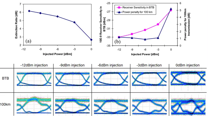
In this paragraph, we evaluate the impacts of injected power on the performances of IL-FP. One of the most important parameters of an optical transmitter used for high-speed transmission is its extinction ratio (ER). The dependence of ER onto injected power of IL-FP directly modulated by 2 Vpp amplitude is shown in figure 8 (a). A degradation of ER when increasing injected power is found. The ER of IL-FP decreases from 6.2 dB at -11 dBm injection to 2.7 dB at 0 dBm injection. The degradation of ER is more significant at strong injection. Consequently, the receiver sensitivity is also degraded when increasing injected power. As reported in figure 8 (b), an increasing of receiver sensitivity at BER of 10-9
in BTB configuration from -33 dBm to -27 dBm is observed when varying injected optical power from -12 dBm to 0 dBm. Therefore, at high injected power, a large locking bandwidth is obtained, but at the expense of the ER.
2 3 4 5 6 7 -12 -9 -6 -3 0 Injected Power [dBm] Ex ti nc tion R a tio [d B ] -35 -33 -31 -29 -27 -25 -12 -9 -6 -3 0 Injected Power [dBm] 10 E -9 R ec ei ve r S en s it iv it y in BTB [ d B m ] 0 1 2 3 4 5 6 P o w e r p e n al ty f o r 10 0k m tr an sm is si on [ d B ] Receiver Sensitivity in BTB Power penalty for 100 km
Figure 8: Dependence of the extinction ratio of IL-FP vs injected power (a) and performances of IL-FP in terms of BTB receiver sensitivity and power penalty for 100 km transmission vs injected power (b). An example of eye diagrams of IL-FP after 100 km vs
injected power is shown at the bottom
The power penalty for transmission over 100 km is also evaluated for different injected power. Results given in figure 8 (b) show that the power penalty is minimal at moderately injected powers (from -9 dBm to -3 dBm), which is confirmed by the eye diagrams after 100 km transmission visible at the bottom of figure 8. The power penalty rapidly increases at high injected power (0 dBm), which is also justified by a strong eye diagram deformation of 0 dBm injected FP-LD after 100 km transmission. The evolution of eye diagrams and power penalty after 100 km transmission versus injected power is quite similar to one of LEF that was previously shown. Therefore, these evaluated performances of IL-FP re-confirm our LEF measurement results reported in 2.3.
(a)
(b)
7720 - 83 V. 1 (p.6 of 10) / Color: No / Format: A4 / Date: 2010-04-12 11:15:58 AM
4. WDM ACCESS TRANSMISSION USING IL-FP AND MULTI-WAVELENGTH
MASTER SOURCE BASED ON QUANTUM-DASH MODE-LOCKED-LASER
In the previous sections, the characterization and the performances evaluation are performed for a FP-LD injected-locked by a low-noise master source based on tunable single-mode laser. However, a practical implementation in access network requires a low-cost master source, which is difficult to be achieved for a tunable laser. As discussed above, FP-LD injection-locked by master source based on spectrally-sliced BLS has been proposed for WDM access to meet the cost requirement. However, the performances of this solution are limited to only 1.25 Gb/s due to high intensity noise [14]. In this section, we demonstrate the operation of a WDM access system using IL-FP at 2.5 Gb/s thanks to the use of a novel multi-wavelength master source based on quantum-dash mode-locked laser (QD-MLL).
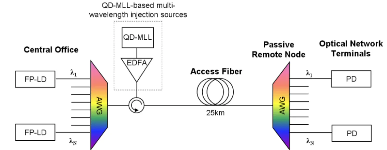
A simplified architecture of WDM access system using IL-FP is described in figure 9. The FP-LDs acting as colorless transmitters are injection-locked by a common master source composed of an amplified MLL. The comb of QD-MLL must fit the channels of array waveguide grating (AWG). Thus, each mode of QD-QD-MLL is selected by an AWG and is optically injected into a FP-LD. The QD-MLL is amplified by an EDFA in order to reach a sufficient power for each mode to achieve injection-locking. Under injection, the FP-LDs are locked into the corresponding injected signal and single-mode operations of these IL-FPs are achieved. The IL-FPs are then directly modulated by an electrical data sequence. The output signals of IL-FPs are multiplexed via the first AWG at the Central Office before propagation over 25 km access fiber. Afterwards, the signals are de-multiplexed via the second AWG at the passive remote note before being detected by photodiodes (PD) at the optical network terminals.
Figure 9: A simplified architecture of WDM access system using IL-FP and multi-wavelength master source based on quantum-dash mode-locked laser
The optical spectrum of QD-MLL biased at 300 mA acting as multi-wavelength master source to injection-lock the FP-LDs is given the figure 10 below. The material processing and the laser diode fabrication technology are reported in [15].
Figure 10: Optical spectrum of QD-MLL
7720 - 83 V. 1 (p.7 of 10) / Color: No / Format: A4 / Date: 2010-04-12 11:15:58 AM
The laser is mode-locked at 42.7 GHz, which corresponds to its free spectral range (FSR). Therefore, we use the tunable AWGs in our experiment to fit the comb of QD-MLL with its channels. However, a realization of QD-MLL having a comb compatible to standardized WDM channels is possible [16]. The wide and flat spectrum of QD-MLL reveals its high potential for multi-wavelength master source in order to support a large number of WDM channels. A low ASE floor is also observed due to the small spontaneous emission ratio of quantum-dash material. Thus, a QD-MLL has a low intensity-noise.
An example of optical spectra of QD-MLL-injected FP-LD is shown in figure 11 (a). We see that a FP-LD injection-locked by one individual mode of QD-ML is highly coherent and has a SMSR higher than 30 dB (hence it can be considered as a single-mode operation). Figure 11 (b) shows the RIN measurement results. As mentioned in the last paragraph, a QD-MLL has a very low intensity-noise. Its RIN floor is even lower than -150 dBc/Hz as reported in figure 11 (b). However, because of mode partition noise (MPN), the RIN strongly increases, mainly for low frequencies, when we select only one individual mode by filtering [11]. However, thanks to injection-locking mechanism, the MPN is suppressed when this individual mode is injected into the FP-LD. The RIN floor of optically injected QD-MLL is reduced to -135 dBc/Hz for -6 dBm of injected power. The RO at 3 GHz of the free-running FP-LD, polarized at 70 mA, is also attenuated and enhanced to around 8 GHz.
Figure 11: An example of optical spectra (a) and the relative intensity noises (b) of FP-LD injection-locked by one individual mode of QD-MLL for -6 dBm of injected power
Finally, the performances of 5 channels among 16 WDM channels obtained by injection-locking of FP-LD using a single multi-wavelength master source based on QD-MLL are evaluated in a WDM access configuration as described in figure 10. The BER measurement results for these channels are reported in figure 12. A negligible power penalty is observed for a transmission over 25 km. The receiver sensitivity at BER of 10-9 varies from -32 dBm to -31 dBm for these
channels after 25 km transmission. This small variation is due to the slight difference of injection conditions between channels (injected power, detuning). A good homogeneity is thus maintained. An illustration of eye diagrams of optically injected QD-MLL FP-LD is inset in figure 12. No eye compression effect is found for transmission over 25 km.
(a) (b)
7720 - 83 V. 1 (p.8 of 10) / Color: No / Format: A4 / Date: 2010-04-12 11:15:58 AM
1,E-11 1,E-10 1,E-09 1,E-08 1,E-07 1,E-06 1,E-05 1,E-04 1,E-03 -35 -34 -33 -32 -31 -30 -29 Received Power [dBm] BE R Ch01 BTB Ch01 25km Ch04 25km Ch08 25km Ch12 25km Ch16 25km
Figure 12: Performances of WDM channels based on optically injected QD-MLL FP-LD. Inset: Eye diagrams of QD-MLL-injected FP-LD
5. CONCLUSION
A FP-LD injection-locked by a single-mode master laser has been characterized. The dependence of main characteristics of IL-FP onto injection parameters is highlighted. The results show that injection-locking has a good potential for noise-reduction when the master laser is a low-noise source. Although the relaxation oscillation frequency is strongly enhanced in injection-locking regime, the improvement of electrical bandwidth of IL-FP is still suffering from the low-frequency roll-off due to parasitic effects. The suppression of adiabatic chirp thanks to injection-locking is deduced via the LEF measurement. It is also demonstrated that the LEF of IL-FP strongly depends on injected power. The performance evaluation of IL-FP is performed and the obtained results show that the power penalty for transmission over 100 km is only 1 dB at 2.5 Gb/s, which is not really different from the one produced when a single-mode laser is used for the external modulation. A degradation of the extinction ratio of IL-FP when increasing injected power is shown. The evolution of performances of IL-FP versus injected power reconfirms our LEF measurement results. Finally, error-free transmission (BER < 10-9) without significant power penalty over 25 km in a WDM access configuration using IL-FP
and a multi-wavelength master source based on QD-MLL demonstrated at 2.5 Gb/s. And it is very important to note that this data rate exceeds the actual limitation at 1.25 Gb/s of conventional solution using master source based on spectrally-sliced BLS.
ACKNOWLEDGEMENT
This study has received the financial support from the French “Agence Nationale de la Recherche” (ANR) through the project Antares.
REFERENCES
[1] R. Lang, "Injection locking properties of a semiconductor laser", IEEE Journal of Quantum Electronics, 18 (6), 976- 983 (1982).
[2] S.-J. Park, C.-H. Lee, K.-T. Jeong, H.-J. Park, J.-G. Ahn, K.-H. Song, "Fiber-to-the-home services based on wavelength-division-multiplexing passive optical network", Journal of Lightwave Technology, 22 (11), 2582- 2591 (2004).
[3] S.-M. Lee, K-M. Choi, S.-G. Mun, J.-H. Moon, C.-H. Lee, "Dense WDM-PON based on wavelength-locked Fabry-Perot laser diodes", IEEE Photonics Technology Letters, 17 (7), 1579-1581 (2005).
[4] K.Y. Park and C.H. Lee, "Intensity Noise in a Wavelength-Locked Fabry–Perot Laser Diode to a Spectrum Sliced ASE", IEEE Journal of Quantum Electronics, 44 (3), 209-215 (2008).
[5] Q.T. Nguyen et al., "16x2.5 Gbit/s downstream transmission in colorless WDM-PON based on injection-locked fabry-perot laser diode using a single quantum dash mode-locked fabry-perot laser as multi-wavelength seeding
7720 - 83 V. 1 (p.9 of 10) / Color: No / Format: A4 / Date: 2010-04-12 11:15:58 AM
source", Optical Fiber Communication Conference / National Fiber Optic Engineers Conference (OFC/NFOEC 2009), 22-26 (2009).
[6] S. Blin, C. Guignard, P. Besnard, R. Gabet, G. M. Stephan, M. Bondiou, "Phase and spectral properties of optically injected semiconductor lasers", Comptes Rendus Physique Semiconductor lasers, 4 (6), 687-699 (2003).
[7] C. Guignard and P. Besnard “Experimental Injection Map of Semiconductor Laser Submitted to Filtered Feedback” special topics in Optical and Quantum Electronics, 38, 411 (2006).
[8] E.K. Lau, H.-K. Sung, M.C. Wu, "Frequency Response Enhancement of Optical Injection-Locked Lasers", IEEE Journal of Quantum Electronics, 44 (1), 90-99 (2008).
[9] C. Harder, K. Vahala, A. Yariv, , "Measurement of the linewidth enhancement factor α of semiconductor lasers", Applied Physics Letters , 42 (4), 328-330 (1983).
[10] Q.-T. Nguyen, P. Besnard, O. Vaudel, A. Shen, G.-H. Duan, "Strong dependence of the Linewidth Enhancement Factor onto an externally injected optical signal for locked Fabry-Perot laser diodes", European Conference on Lasers and Electro-Optics 2009 and the European Quantum Electronics Conference (CLEO Europe - EQEC 2009), 14-19 (2009).
[11] K. Petermann, "Laser Diode Modulation and Noise", Kluwer Academic Publishers (1991).
[12] L. Bjerkan, A. Royset, L. Hafskjaer, D. Myhre, "Measurement of laser parameters for simulation of high-speed fiberoptic systems", Journal of Lightwave Technology, 14 (5), 839-850 (1996).
[13] B. Zhang et al., "Adjustable Chirp Injection-Locked 1.55-μm VCSELs for Enhanced Chromatic Dispersion Compensation at 10-Gbit/s", Optical Fiber Communication Conference / National Fiber Optic Engineers Conference (OFC/NFOEC 2008), 24-28 (2008).
[14] J.H. Lee et al., "WDM-Based Passive Optical Network Upstream Transmission at 1.25 Gb/s Using Fabry-Perot Laser Diodes Injected With Spectrum-Sliced, Depolarized, Continuous-Wave Supercontinuum Source", IEEE Photonics Technology Letters, 18 (20), 2108-2110 (2006).
[15] F. Lelarge et al., "Recent Advances on InAs/InP Quantum Dash Based Semiconductor Lasers and Optical Amplifiers Operating at 1.55 μm", IEEE Journal of Selected Topics in Quantum Electronics, 13 (1), 111-124 (2007).
[16] A. Akrout et al., "Separate Error-Free Transmission of Eight Channels at 10 Gb/s Using Comb Generation in a Quantum-Dash-Based Mode-Locked Laser", IEEE Photonics Technology Letters, 21 (23), 1746-1748, (2009).