Science Arts & Métiers (SAM)
is an open access repository that collects the work of Arts et Métiers Institute of
Technology researchers and makes it freely available over the web where possible.
This is an author-deposited version published in: https://sam.ensam.eu Handle ID: .http://hdl.handle.net/10985/8410
To cite this version :
Ngac Ky NGUYEN, Damien FLIELLER, Xavier KESTELYN, Eric SEMAIL - Analytical Optimal Currents for Multiphase PMSMs Under Fault Conditions and Saturation - In: The 40th Annual Conference of the IEEE Industrial Electronics Society, United States, 20141029
-Communication Internationale avec actes - 2014
Any correspondence concerning this service should be sent to the repository Administrator : [email protected]
Analytical Optimal Currents for Multiphase PMSMs
Under Fault Conditions and Saturation
Ngac Ky Nguyen1, Damien Flieller2, Xavier Kestelyn1, Eric Semail1 1Laboratory of Electrical Engineering and Power Electronics
Art et Métiers ParisTech Lille, France
2GREEN Laboratory – ERGE Group
INSA of Strasbourg Strasbourg, France
1Email. {ngacky.nguyen; xavier.kestelyn; eric.semail}@ensam.eu 2Email: [email protected]
Abstract— An original analytical expression is presented in
this paper to obtain optimal currents minimizing the copper losses of a multi-phase Permanent Magnet Synchronous Motor (PMSM) under fault conditions. Based on the existing solutions [i]opt1 (without zero sequence of current constraint) and [i]opt2 (with zero sequence constraint), this new expression of currents [i]opt3 is obtained by means of a geometrical representation and can be applied to open-circuit, defect of current regulation, current saturation and machine phase short-circuit fault. Simulation results are presented to validate the proposed approach.
Keywords— Multiphase PMSM, optimal currents, fault tolerance, open-circuit, short-circuit, torque pulsation, saturation.
I. INTRODUCTION
Drives reliability is a key parameter in some critical applications and its improvement can be obtained in several ways. With a conservative design, the system is well operated below its rated value, and therefore its expected lifetime increases. However, in this case, system efficiency may be reduced and the system may not be able to withstand sporadic faults. This is particularly true for power electronics components whose failures are yet mostly unpredictable [1].
To increase the drive availability, fault tolerance has been introduced in the last decades. Fault tolerance can be applied to the inverter and/or to the electric machine [2]. Specific configurations of three-phase and multi-phase drives have been investigated for their properties in healthy and faulty conditions.
Multi-phase drives have additional degrees of freedom when compared with three-phase machines [3, 4]. These degrees of freedom can be used for different purposes, such as additional torque generation or fault tolerance when a part of the system fails. Fault detection and control reconfiguration of the drive in case of open-circuit faults have been extensively studied in the past years [5-8]. On the other hand, only a few works have addressed the problem of inverter switch short-circuit faults [9], except in topologies
with additional components such as fuses and parallel thyristors which are not used in healthy operation [10, 11].
When a fault occurs, it will be interesting to keep a minimum operability or even an operation at rated power as before the fault if the machine-converter set allows it. If not, from the control point of view, new references of current are required to keep a reduced constant torque. Several works presented analytical formulas of optimal stator currents which lead to the desired electromagnetic torque while minimizing the ohmic losses under open-circuit fault [12-18]. In general, we need two independent phases to generate a rotation of the stator magnetic field. In practice, if the machine has a star coupling, we need three healthy phases. From the point of view of the voltage source inverter and PMSM, it is difficult to control the currents when an important number of phases is affected because the magnitude of the currents in the healthy phases increases quickly and the inverter can get saturated. Additionally, harmonics at high frequencies appear in the current lead to a necessary performant current controller. To deal with this problem, a constrained optimization method (maximum voltage and maximum current) should be considered. This work is reported in [19] for open-phase fault.
When the current on one of phases get saturated, the problematic is more complex than in the event of open-circuit faults because in this case the fault current is different to zero. Let us suppose that there is a problem of current regulation, the current on this phase can take an unspecified form but its max value is lower than the one authorized. In two cases (saturation or defect of current control), the torque created by the faulty phase degrades the normal functioning of PMSM. Short-circuit inverter switch fault can occur at any time and it degrades also the motor functioning by developing a torque ripple. One solution which can be envisaged for adaptive control is to use Artificial Intelligence (AI) technique. In [14], a simple neural network, called Adaptive Linear Network (Adaline), is proposed for estimating the periodic functions derived from the back-EMF, the desired torque and the disturbance torque (coming from fault types). Thanks to its capacity of
learning, the Adaline can adapt itself to several fault types (open-circuit for example) and derive stator currents to keep a desired torque. Based on this approach, currents and back-EMF are always kept in phase and copper losses are minimized.
Based on the works presented in [12, 14, 20], two currents vectors [i]opt-1 and [i]opt-2 corresponding to two
optimal solutions for open-circuit faults, i.e. faulty phase currents are null, are shown. A geometric representation of [i]opt-1and[i]opt-2 is given. Based on this presentation, a new
expression of the current vectors for the case when faulty phase currents are different from zero is given.
This paper is organized as follows: Section II develops the proposed expression based on two analytical existing formulas. Section III presents some simulation results under four types of fault: open-circuit, current controller problem, current saturation and short-circuit of machine phase. Section IV gives some conclusions.
II. OPTIMIZATION WITH ZERO NEUTRAL CURRENT CONSTRAINT
The stator current and the back-EMF vectors of a multiphase PMSM can be defined for n phases respectively by:
[ ] [
1 2]
T z n i i i i = i (1)[ ] [
1 2]
T z n e e e e = e (2)Let us define the matrix
[ ]
Q :[ ]
1 0 0 0 0 0 0 0 0 0 1 0 0 0 0 0 0 1 = Q (3)where the value of diagonal component is 1 for healthy phases and 0 for faulty phases.
The back-EMF vector for the n n− d healthy phases of
the machine (nd is the number of faulty phases) is:
[ ]
e′ =( )
Q[ ]
e (4) The electromagnetic torque can be expressed as:[ ][ ]
1 em c F H T =T T + Ω ′ + e i (5)Tc is the cogging torque, TF is the torque created by the
faulty phases.
[ ]
i H the currents of healthy phases and Ω the rotor speed.If a constant torque Tem is required, it is necessary that
the torque created by the currents of the healthy phases compensates the disturbance torque TF. Normally, cogging
torque of PMSM machine contains very high frequency components. A compensation of cogging torque requires a
large band-width of the current controller. It is interesting to notice that at high speed (high frequency), the torque has no impact on the motor’s speed because it can be eliminated by mechanical system. In this paper, we do not take into account the cogging torque in current calculation.
Let us consider a PMSM machine having a wye connection and where the phase k is faulty. Firstly, it is interesting that the current of phase k is different to zero. This current corresponds for example to a saturation or current regulation malfunctioning. It can be noticed that the case where there are nd faulty phases can be generalized.
A. Optimal current determination under fault conditions
Let us define the currents as:
[ ] [ ] [ ]
i = i F + i H (6)[ ]
i F the currents of faulty phases. First, we consider:[ ]
i F =ik(only the kth phase is faulty).
The constraint on the homopolar current is written as follows:
[ ] [ ] [ ] [ ][ ]
1 1 1 n T T j k j j k i i = ≠ = = = −∑
w i w Q i (7) All points M satisfying the constraint (7) are belong to the hyperplane( )
H1 whose equation is[ ] [ ][ ]
1T
k
i
= −
w Q i .
The vector
[ ]
w1 is normal to( )
H1 and contains thediagonal values of the matrix
[ ]
Q . For the matrix[ ]
Qgiven in (3), the vector
[ ]
w1 is:[ ] [
1 1 0 1 1]
T=
w (8)
From (5), we can rewrite:
[ ][ ]
k em c e ik H T =T + + ′ Ω Ω e i (9)(9) is the expression of the hyperplane
( )
P all of whose points give a constant electromagnetic torque. It is obvious that the constraints (7) and (9) are satisfied by the current vectors whose terminals must belong to the intersection of two hyperplanes( )
H1 et( )
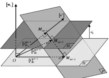
P . In order to optimize thecopper losses, the magnitude of the current vector has to be minimized. In Fig. 1, the point Mopt-3 corresponds to the
optimal solution.
Introducing the copper losses as the function to minimize, the currents
[ ]
i H can be obtained by resolving two equations (7) and (9) thanks to the Lagrange multiplier. In our study, we show that this vector of current OMopt-3 canbe determined from two existing solutions presented in [14]. By taking into account the torque created by phase k, the expression of current
[ ]
opt 1H −
Fig. 1. Hyperplan representing the optimal currents.
Fig. 2. Representation of the optimal currents.
[ ][ ]
[ ]
[ ] [ ]
[ ]
1 1 k k em c opt opt T H e i T T − − − − Ω Ω ′ = = ′ ′ Q i i e e e (10)In the same way, the expression of the current
[ ]
i optH −2 is written as follows:[ ][ ]
[ ]
[ ] [ ]
[ ]
2 2 k k em c opt opt T H e i T T − − − − Ω Ω ′′ = = ′′ ′′ Q i i e e e (11)where the vector
[ ]
e′′ is defined as:[ ] [ ] [ ] [ ] [ ]
[ ]
1 1 2 1 T ′′ = ′ − ′ w e e w e w (12)The vector
[ ]
e′′ does not contain the homopolar component of the back-EMF.In Fig. 2, it can be noticed that the current
[ ]
i optH −3 , represented by the vector OMopt-3, is a combination of twovectors OMopt-1 and OMopt-2. So, we can write:
[ ][ ]
opt−3[ ][ ]
opt−2 α(
[ ][ ]
opt−1[ ][ ]
opt−2)
= + −
Q i Q i Q i Q i (13)
The currents
[ ]
i optH −2 satisfying the zero sequence of current lead to:[ ] [ ][ ]
21 0
T opt − =
w Q i (14)
From (7), (13) and (14), the proportional coefficient is obtained by:
[ ] [ ]
3[ ] [ ]
1( )
1 1 T opt T opt k H α H α i − = − = ⋅ − w i w i (15)[ ] [ ]
1 1 k T opt H i α = − − w i (16)Substituting (16) into (13), the current
[ ]
opt 3 H − i can be expressed as:[ ][ ]
[ ]
[ ]
(
[ ]
[ ]
)
[ ] [ ]
1 2 3 3 2 1 1 opt opt k H Hopt opt opt
T opt H H H i − − − − − − − = = − i i Q i i i w i (17)
Expression (17) gives the optimal currents in the case where the kth phase is faulty and the current i
k is different to
zero. It is obvious that if ik=0, the current
[ ]
i optH −3 =[ ]
i optH −2,which means the hyperplane
( )
H1 is closed to thehyperplane
( )
H ′1 .Expression (17) can be generalized for the case of nd
faulty phases. Indeed, to keep a constant torque, the sum of all the current of the healthy phases have to be equal to the sum of the nd currents of the faulty phases. Equation (7) is
rewritten as follows:
[ ] [ ] [ ] [ ][ ] [ ] [ ] [ ] [ ] [ ]
1 1 1 1 T T T T T F ′ ′ = = − = − w i w Q i w Q i w i (18)where we define the vector
[ ]
w1′ as the complementary ofthe vector
[ ]
w1 . For[ ]
w1 given in (8), the vector[ ]
w1′ isexpressed as:
[
]
1 0 1 0 0 T ′ = w (19)From (18) and (17), we deduce:
[ ]
[ ]
[ ] [ ]
(
[ ]
[ ]
)
[ ] [ ]
1 2 3 2 1 1 1 opt opt H H opt opt T T opt H H F H − − − − − − ′ = − i i i i w i w i (20)III. SIMULATION RESULTS
In order to verify the expression (20), a five-phase machine with sinusoidal back-EMF is considered for simulation. The reference torque is set to 10 N.m. Fig. 3 shows the shape of the back-EMF. Tab. I gives the parameters of the study five-phase PMSM. It is a low voltage machine for automotive application.
Different simulations are presented: open-circuit, current controller fault, current saturation and phase short-circuit fault.
TABLE I. MACHINE PARAMETERS Parameter Value Phase resistance Rs = 9.1 [mΩ] Phase inductance Ls = 0.09 [mH] Mutual inductance 1 M1 = 0.02 [mH] Mutual inductance 2 M2 = -0.01 [mH]
Pole pair number p = 7
Speed normalized back-EMF E Ω=0.1358 (V.s.rad )−1
Maximum voltage of DC bus 60 [V] Maximum RMS current 147 [A] Short-circuit current 198 [A] Maximum speed 16000 [rpm] Maximum torque 50 [N.m] Maximum power 15 [kW]
Fig. 3. Shape of the back-EMF of studied PMSM
A. Open-circuit fault
As mentioned before, when an open-circuit fault occurs, the currents
[ ]
i optH −3 =[ ]
i optH −2 because[ ] [ ]
1 0T F
′ =
w i . If a star-coupling is realized, the maximum number of open-circuit phases considered is two. In our simulation, the phase b and the phase c are opened.
Fig. 4 shows the simulation results of the open-circuit fault. The currents in the healthy phases become non-sinusoidal. The electromagnetic torque is equal to 10 N.m. It can be noticed that phase currents have not the same magnitude and the phase shift between them is always 2
5 π
. High harmonics of current can lead to the inverter saturation (Imax and Vmax) and impose high frequency of PWM as well
as high bandwidth of current controller. In this simulation, the highest of current harmonic is up to 9. At high speed, it is more complex to control properly this harmonic component of the current. In some cases, if the torque ripple is not mandatory, it can be imagined that only the 1st and the
3rd harmonics are used.
Fig. 4. Simulation results of open-circuit fault: phase b and phase c in open-circuit
[ ]
ioptH−3=[ ]
ioptH−2. a) Currents of healthy phases; b) Electromagnetic torque; c) Spectrum of phase currentsAnother interesting point is to look at the faulty phases order. In our simulation, maximum magnitude of current reaches 105 [A] when phases b and c are open-circuited. If phases b and are open-circuited then the maximum value of the current is reduced.
If the constraints of voltage and current have to be respected, it is impossible, with author’s knowledge, to obtain analytical solution. In this case, some works have been proposed based on numerical calculus. The function
fmincon is employed in [19, 21]. With this solution, the
0 0.2 0.4 0.6 0.8 1 -0.2 -0.1 0 0.1 0.2 Speed-normalized back-EMF [Electric turn] [V .s/ ra d] 0 0.2 0.4 0.6 0.8 1 -100 -50 0 50 100
Healthy phase currents
[A ] 0 0.2 0.4 0.6 0.8 1 0 5 10 15 Electromagnetic Torque [Electric turn] [N .m ] 0 2 4 6 8 10 0 0.2 0.4 0.6 0.8
1 Spectrum of phase current
Harmonic N or m al iz ed m agni tude
i
ai
di
e a) b) c)phase shift between the phase currents is not 2 5
π
and the same magnitude of phase current can be obtained. However, there are some drawbacks with the fmincon function:
The initial condition has to be optimized
For real-time implementation, it is necessary to use look-up tables to stock the numerical values obtained during the optimization process. It requires a big memory consequently.
B. Fault of the current controller
It may occur that one of the current controllers fails. In this case, the current of the faulty phase is unpredictable. Fig.5 gives simulation results in one case where the current controller of phase a is failed. Seeing that ia is not null, there
is torque created by the phase a, called Tem-a. To compensate
Tem-a the four currents ib ic id and ie have to develop Tem-ref -
Tem-a with Tem-ref-=10 [N.m]. The fault detection is required
and the faulty current has to be measured. For this, an adaptive solution-based on Artificial Neural Networks (ANN) is possible. This work is presented in [14] where the authors propose an Adaptive Linear Network (Adaline) to estimate an optimal function which is a coefficient between the current vector and the back-EMF vector. In healthy case, this coefficient is constant. In faulty cases, it becomes a periodic function whose harmonics spectrum depends on the nature of the fault. With the aid of Adaline, the current giving the desired torque can be obtained.
Fig. 5. Simulation results in the studied case where the current controller of phase a is faulty. Top: machine phase currents;
Bottom: electromagnetic torque.
Fig. 6. All of phases are saturated at 27.5 A. Top: machine’s currents
[ ]
ioptH−3; Bottom: electromagnetic torque.C. Saturation of currents
In this simulation, the value of the different variables (voltage, torque and current) is reduced to keep homogeneity with the two previous sections. Thermal maximum current is set to 27.5 [A] and torque reference is 10 [N.m].
In this case, a constant torque condition is satisfied when only two currents are saturated simultaneously car a five-phase star-coupling machine is considered. Fig. 6 shows the currents and the torque obtained. The current differs lightly sinusoidal waveform due to saturation. All peak values are equal to 27.5 [A]. The torque is equal to the reference value 10 [N.m].
D. Machine phase short-circuit fault
Fig. 7 gives an example of phase short-circuit fault. The Triacs are used to isolate the faulty phases. The phase a, after being isolated from inverter, is circuited by a short-circuit current iSC-a due to the back-EMF and the mutual
inductions. Theoretically, this current is determinable by the electric model of the machine. In our simulation, this current is simply measured. One more time, we find the same problems as in the two aforementioned cases where it was necessary to compensate the torque created by iSC-a.
0 2 4 6 8 10 12 14 -50 0 50 Phase currents [A ] 0 2 4 6 8 10 12 14 -2 0 2 4 6 8 10 12 Electromagnetic Torque [Electric angle] [N .m ] 0 0.2 0.4 0.6 0.8 1 -30 -20 -10 0 10 20
30 Healthy phase currents
[A] 0 0.2 0.4 0.6 0.8 1 0 5 10 15 Electromagnetic Torque [Electric turn] [N. m ]
i
ai
bi
ci
di
e current controller faulti
ai
bi
ci
di
eFig. 7. Phase a short-circuit fault.
The short-circuit current is expressed as:
1 b e 2 c d a SC a s s di di di di e M M dt dt dt dt i L s R − + + + + = − ⋅ + (21)
If the mutual induction and the stator resistance are neglected, the magnitude of iSC-a is given approximately by:
a a SC a s s e i p L L φ − = Ω = (22)
It is obvious that this value of the magnitude of the short-circuit current of the phase a is constant and depends on the flux and the phase inductance.
Fig. 8. Simulation results of short-circuit fault of phase a: top: currents; bottom: PMSM torque.
Fig. 8 gives simulation results of the phase a short-circuit fault. The faulty current has high amplitude (145 [A]) due to a very small stator inductance because the PMSM is designed for low voltage application at high speed. If the torque is maintained as before, the magnitudes of current of the other phases increase rapidly which can damage the PMSM. That is why a reduced torque would be proposed to keep a minimum functioning. The value of torque in short-circuit condition has to be determined for an optimum operation. In our simulation, this value is fixed at half of the torque in healthy functioning.
IV. CONCLUSION
An original analytical expression for optimal currents under fault conditions is presented in this paper. This expression is derived from two existing solutions thanks to the geometrical approach. At first, one faulty phase has been considered. A general case where there are nd faulty phases
has been proposed. Several types of faults have been simulated and the reconfiguration of the control has been defined in order to maintain the torque to a constant value as before the fault. The results of simulation show that the proposed method allows to find again the right values of current for fault solving.
Nevertheless, voltage and current constraints are not taken into account under fault conditions in this paper. In practice, it will be necessary to take into account this kind of limitations.
An important point before looking for a solution which faces the fault is how the faults can be detected? For this, AI techniques can be considered as good candidates. A lot of time is required for the structure design but their (AI) adaptive capacity make them a powerful tool for either solving (determination of current references) or detecting different types of faults.
REFERENCES
[1] Y. Shaoyong, X. Dawei, A. Bryant, P. Mawby, L. Ran, and P. Tavner, "Condition Monitoring for Device Reliability in Power Electronic Converters: A Review," Power Electronics, IEEE
Transactions on, vol. 25, no. 11, pp. 2734-2752, 2010.
[2] E. Semail, X. Kestelyn, and F. Locment, "Fault tolerant multiphase electrical drives: the impact of design," European Physical
Journal-Applied Physics, vol. 43, no. 2, pp. 159-163, Aug 2008.
[3] E. Levi, "Multiphase Electric Machines for Variable-Speed Applications," Industrial Electronics, IEEE Transactions on, vol. 55, no. 5, pp. 1893-1909, 2008.
[4] L. Parsa and H. A. Toliyat, "Five-phase permanent-magnet motor drives," Industry Applications, IEEE Transactions on, vol. 41, no. 1, pp. 30-37, 2005.
[5] F. Meinguet, X. Kestelyn, E. Semail, and J. Gyselinck, "Fault Detection, Isolation and Control Reconfiguration of Three-Phase PMSM Drives," 2011 Ieee International Symposium on Industrial
Electronics (Isie), 2011.
[6] F. Meinguet, P. Sandulescu, X. Kestelyn, and E. Semail, "A Method for Fault Detection and Isolation Based on the Processing of Multiple Diagnostic Indices: Application to Inverter Faults in AC Drives," Vehicular Technology, IEEE Transactions on, vol. 62, no. 3, pp. 995-1009, 2013.
[7] A. Sarikhani and O. A. Mohammed, "Inter-Turn Fault Detection in PM Synchronous Machines by Physics-Based Back Electromotive Force Estimation," Industrial Electronics, IEEE Transactions on, vol. 60, no. 8, pp. 3472-3484, 2013. 0 5 10 15 20 25 -200 -100 0 100 200 Phase currents [A ] 0 5 10 15 20 25 -2 0 2 4 6 8 10 12 Electromagnetic Torque [Electric angle] [N .m ] Short-circuit of phase a
i
ai
bi
ci
di
e[8] A. Gandhi, T. Corrigan, and L. Parsa, "Recent Advances in Modeling and Online Detection of Stator Interturn Faults in Electrical Motors," Industrial Electronics, IEEE Transactions on, vol. 58, no. 5, pp. 1564-1575, 2011.
[9] Y. Wang, T. A. Lipo, and D. Pan, "Robust operation of double-output AC machine drive," in Power Electronics and ECCE Asia
(ICPE & ECCE), 2011 IEEE 8th International Conference on, 2011,
pp. 140-144.
[10] B. A. Welchko, T. A. Lipo, T. M. Jahns, and S. E. Schulz, "Fault tolerant three-phase AC motor drive topologies: a comparison of features, cost, and limitations," Power Electronics, IEEE
Transactions on, vol. 19, no. 4, pp. 1108-1116, 2004.
[11] R. R. Errabelli and P. Mutschler, "Fault-Tolerant Voltage Source Inverter for Permanent Magnet Drives," Power Electronics, IEEE
Transactions on, vol. 27, no. 2, pp. 500-508, 2012.
[12] S. Dwari and L. Parsa, "An Optimal Control Technique for Multiphase PM Machines Under Open-Circuit Faults," Industrial
Electronics, IEEE Transactions on, vol. 55, no. 5, pp. 1988-1995,
2008.
[13] S. Dwari and L. Parsa, "Fault-Tolerant Control of Five-Phase Permanent-Magnet Motors With Trapezoidal Back EMF," Industrial
Electronics, IEEE Transactions on, vol. 58, no. 2, pp. 476-485,
2011.
[14] D. Flieller, N. K. Nguyen, P. Wira, G. Sturtzer, D. O. Abdeslam, and J. Merckle, "A Self-Learning Solution for Torque Ripple Reduction for Nonsinusoidal Permanent-Magnet Motor Drives Based on Artificial Neural Networks," Industrial Electronics, IEEE
Transactions on, vol. 61, no. 2, pp. 655-666, 2014.
[15] X. Kestelyn and E. Semail, "A Vectorial Approach for Generation of Optimal Current References for Multiphase Permanent-Magnet Synchronous Machines in Real Time," Ieee Transactions on
Industrial Electronics, vol. 58, no. 11, pp. 5057-5065, Nov 2011.
[16] F. Locment, E. Semail, and X. Kestelyn, "Vectorial Approach-Based Control of a Seven-Phase Axial Flux Machine Designed for Fault Operation," Ieee Transactions on Industrial Electronics, vol. 55, no. 10, pp. 3682-3691, Oct 2008.
[17] F. Baudart, B. Dehez, E. Matagne, D. Telteu-Nedelcu, P. Alexandre, and F. Labrique, "Torque Control Strategy of Polyphase Permanent-Magnet Synchronous Machines With Minimal Controller Reconfiguration Under Open-Circuit Fault of One Phase," Industrial
Electronics, IEEE Transactions on, vol. 59, no. 6, pp. 2632-2644,
2012.
[18] E. Robert-Dehault, M. F. Benkhoris, and E. and Semail, "Study of a 5-phases synchronous machine fed by PWM inverters under fault conditions," in Proc. of ICEM' 02, Brugge, Belgium, 2002.
[19] A. Mohammadpour and L. Parsa, "A Unified Fault-Tolerant Current Control Approach for Five-Phase PM Motors with Trapezoidal Back EMF under Different Stator Winding Connections," Power
Electronics, IEEE Transactions on, vol. 28, no.7, pp. 3517-3527,
2012.
[20] D. Flieller, N. K. Nguyen, H. Schwab, and G. and Sturtzer, Control
of Non-Conventional Synchronous Motors. Chapter 3: Synchronous Machines in Degraded Mode: ISTE Ltd and John Wiley & Sons
Inc., 2012.
[21] L. Lu, E. Semail, L. Kobylanski, and X. Kestelyn, "Flux-Weakening Strategies for a Five-Phase PM Synchronous Machine," Proceedings
of the 2011-14th European Conference on Power Electronics and Applications (Epe 2011), 2011.
Ngac Ky Nguyen (M’13) received the B.Sc. degree in electrical engineering from Ho Chi Minh City University of Technology, Ho Chi Minh City, Vietnam, in 2005, the M.Sc. degree in electrical and electronic engineering from École Polytechnique de l’Université de Nantes (PolyTech Nantes), Nantes, France, in 2007, and the Ph.D. degree in electrical and electronic engineering from the University of Haute Alsace, Mulhouse, France, in 2010.
From 2011 to 2012, he was with the Department of Electrical Engineering, Institut National des Sciences
Appliquées (INSA) of Strasbourg, Strasbourg, France. Since September 2012, he has been an Associate Professor with the Laboratory of Electrical Engineering and Power Electronics of Lille (L2EP), Centre d’Enseignement et de Recherche, Arts et Métiers ParisTech, Lille, France. His research interests are modeling and control of multiphase synchronous motors and power converters in degrade modes.
Damien Flieller received the M.Sc. degree in electrical engineering from the Ecole Normale Supérieure, Cachan, France, in 1988 and the Ph.D. degree in electrical engineering from the University of Paris, Paris, France, in 1995.
Since 1995, he has been an Associate Professor with the Department of Electrical Engineering, Institut National des Sciences Appliquées (INSA) of Strasbourg, Strasbourg, France, where he is currently the Director of the Electrical Engineering Research Team (ERGE Group). His research fields are modeling and control of synchronous motors, active filters, and induction heating converters.
Xavier Kestelyn (M’08) was born in Dunkerque, France, in 1971. He received the Ph.D. degree in electrical engineering from Lille University, Lille, France, in 2003.
After ten years as a teacher of electrical engineering in high school, he is currently an Associate Professor of electrical engineering with the Laboratory of Electrical Engineering and Power Electronics of Lille (L2EP), Centre d’Enseignement et de Recherche, Arts et Métiers ParisTech, Lille, France. His research interests include the modeling and control of multimachine systems such as multiphase machines and overactuated industrial robots.
Eric Semail (M’02) received the M.S. degree from Ecole Normale Supérieure, Paris, France, in 1986 and the Ph.D. degree, with specializations in tools and studying method of polyphase electrical systems and generalization of the space vector theory, from Lille University, Lille, France, in 2000.
He is currently with the Laboratory of Electrical Engineering and Power Electronics of Lille (L2EP), Centres d’Enseignement et de Recherche, Arts et Métiers ParisTech, Lille, where he became an Associate Professor in 2001 and a full Professor in 2010. In L2EP, his fields of interest include the design, modeling, and control of multiphase drives (converters and ac drives). More generally, he studies multimachine and multiconverter systems. His application fields are automotive, marine, and offshore wind power.
![Fig. 4. Simulation results of open-circuit fault: phase b and phase c in open-circuit [ ]i opt H − 3 = [ ]i optH − 2](https://thumb-eu.123doks.com/thumbv2/123doknet/7412451.218359/5.893.61.416.310.636/fig-simulation-results-circuit-fault-phase-phase-circuit.webp)
![Fig. 6. All of phases are saturated at 27.5 A. Top: machine’s currents [ ]i opt H − 3 ; Bottom: electromagnetic torque](https://thumb-eu.123doks.com/thumbv2/123doknet/7412451.218359/6.893.71.403.574.1032/fig-phases-saturated-machine-currents-opt-electromagnetic-torque.webp)
![Fig. 8 gives simulation results of the phase a short-circuit fault. The faulty current has high amplitude (145 [A]) due to a very small stator inductance because the PMSM is designed for low voltage application at high speed](https://thumb-eu.123doks.com/thumbv2/123doknet/7412451.218359/7.893.62.404.594.1033/simulation-results-circuit-current-amplitude-inductance-designed-application.webp)
