OATAO is an open access repository that collects the work of Toulouse researchers and
makes it freely available over the web where possible.
This is an author-deposited version published in :
http://oatao.univ-toulouse.fr/
Eprints ID : 9149
To link to this article : DOI: 10. 1109/TIA.2012.2210176
URL : http://dx.doi.org/10.1109/TIA.2012.2210176
O
pen
A
rchive
T
OULOUSE
A
rchive
O
uverte (
OATAO
)
To cite this version : Egalon, Julie and Caux, Stéphane and
Maussion, Pascal and Souley, Majid and Pateau, Olivier Multi
phase system for metal disc induction heating: modelling and RMS
current control. (2012) IEEE Transactions on Industry
Applications, vol. 48 (n° 5). pp. 1692-1699. ISSN 0093-9994
Any correspondence concerning this service should be sent to the repository
administrator:
[email protected]
㩷Multi phase system for metal disc induction heating:
modelling and RMS current control
Julie Egalon
Université de Toulouse; INPT, UPS; CNRS, LAboratoire PLAsma et Conversion d’Energie ENSEEIHT, 2 rue Camichel, 31071 Toulouse Cedex 7, FranceStéphane Caux
Member, IEEE, Université de Toulouse; INPT, UPS; CNRS, LAboratoire PLAsma et Conversion d’Energie, ENSEEIHT, 2 rue Camichel, 31071 Toulouse Cedex 7, FrancePascal Maussion
Member, IEEE, Université de Toulouse; INPT, UPS; CNRS, LAboratoire PLAsma et Conversion d’Energie, ENSEEIHT, 2 rue Camichel, 31071 Toulouse Cedex 7, France, [email protected] niv-tlse.frMajid Souley
EDF Eco-Efficiency & Indust.Process Dept, Av. des Renardières, 77818 Moret sur Loing,
France
Olivier Pateau
EDF Eco-Efficiency & Indust.Process Dept, Av. des Renardières, 77818 Moret sur Loing,
France
Abstract - This paper presents a multi phase induction system
modelling for a metal disc heating and further industrial applications such as hot strip mill. An original architecture, with three concentric inductors supplied by three resonant current inverters leads to a reduced element system, without any coupling transformers, phase loop, mobile screens or mobile magnetic cores as it could be found in classical solutions. A simulation model is built, based on simplified equivalent models of electric and thermal phenomena. It takes into account data extracted from Flux2D® finite element software, concerning the energy transfer between the inductor currents and the piece to be heated. It is implemented in a versatile software PSim, initially dedicated to power electronic. An optimization procedure calculates the optimal supply currents in the inverters in order to obtain a desired power density profile in the work piece. The paper deals with The simulated and experimental results are compared in open-loop and closed loop. The paper ends with a current control method which sets RMS inductor currents in continuous and digital conditions.
Index Terms – induction heating, metal industry, current
control, electromagnetic induction, multi phase.
I. INTRODUCTION
Nowadays, induction heating systems are expanding in industry because of the induced advantages. High power density can be reached quickly with an increased flexibility and thanks to the associated power electronics, a fine control of the heat profile can be implemented. It is also a good solution when heating inaccessible parts of a piece is necessary [1][2]. This kind of heating is most often used in steel and metal working industries for heat treating, welding and melting, for drying, for merging and even in the food industry. But it also appears in degreasing, stripping, or galvanizing applications. Compared with convection or radiation ovens, this technique provides better performance for heating metal parts because the heat is generated directly inside the material. Moreover, the induction heating systems have better power/volume ratios and do not locally generate any kind of exhaust gases.
There are two general types of induction heating systems for strip heating, depending on the flux direction: transversal flux in Fig.1.a or longitudinal flux in Fig. 1.b.
This work will only focus on high power density and multi phase systems for industry applications and on the first type of flux generation which is the most suitable for thin disc or strip heating. The future objective of this work is the dynamic control of high power (>1MW) induction systems for industrial applications such as metal strip heating in a hot strip mill.
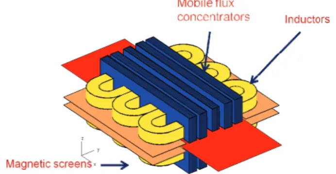
Fig. 1a : transverse flux inductor Fig.1b : longitudinal flux inductor Conventional control solutions for multi inductor systems [2][3][4] advocate the use of several inductors with mobile magnetic screens and mobile flux concentrators (Fig.2). The additional devices permit to apportion the magnetic fields produced and thus to adapt the system to different formats of material and changes in position in order to reach the desired temperature gradients. The processing lines are then subject to mechanical adjustments and/or maintenance as often as necessary to change the material to be heated. It is important to notice that without any model, the desired power profile is obtained by successive trail and error setting tests which are time consuming.
Numerous papers and patents have been published on the automatic control of single phase induction heating systems [5-9] but fewer on multi phase generators. Even in that particular case, they often present a rather complex solution with one dc/dc converter (or one rectifier) plus one resonant inverter per phase [10][11]. One solution [12] proposes to manually change the coil connection in order to adapt the generator to the load, while another implies some variable passive elements [13] or some decoupling transformers between the different phases [14] which are certainly bulky and costly. Parallel connection of serial resonant inverters behind only one rectifier is possible [15] but in rather high frequency and with additionnal serial inductances. A last, a reduced set of papers deal with the specific problem of multiphase electronic or digital current control [16-19].
In this work, a reduce element system is first proposed with several inductor coils in order to obtain flat power density and temperature profile in the stainless steel piece to be heated. The resulting high complexity, mainly due to interactions between the converter, the inductors and the heat piece, makes the modelling rather difficult. Nevertheless it is possible to separate the system into two parts [19] : on the one hand a power part, on the other hand a thermal part. Few software like Flux2D® allow magneto-thermal studies and their complexity and their long simulation time make them unsatisfying (long hours or days of simulation). To overcome these drawbacks, a simplified model of the complete system was developed, including control, power electronics, load thermal behaviour and power exchange between the supply and the loads. The whole model is presented with the comparison between open-loop and experimental results. In the last part, a simple current control is tested in digital conditions.
II. ELECTRICAL AND THERMALMODEL
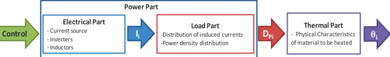
The reduced element system is composed by 3 inductor concentric coils arranged face to face in a transverse flux and a disk plate i.e. the load to be heated. Fig. 3 presents a simplified diagram of the coil/disc arrangement, while Fig4. shows the exact concentric and face-to-face configuration. Each coil is supplied by a resonant inverter but with a common ac/dc rectifier + inductor as a controlled current source connected to the grid. The model can be divided into three parts: the electrical part with the inverters, capacitors and coupled inductors, the electrical/power part with a current/power transformation inside the load disc and the thermal part (Fig. 5).
Fig. 3. Coils and work piece schematic coupling
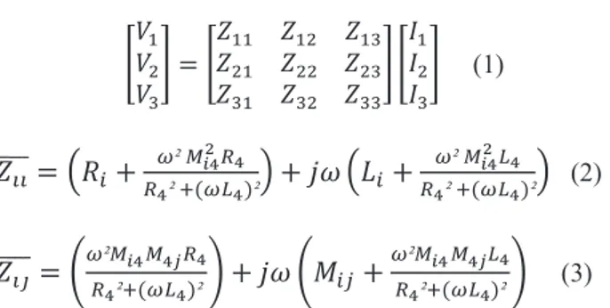
The first one can be represented by four electrical circuits (one for each coil and the last for the material to be heated which is flowed by currents in short circuit with zero voltage) reduced to three relationships, presented in a matrix way in (1). The system can be described by an impedance matrix [Zij] linking the three inductor voltages
V1, V2 and V3 to the associated inductor currents I1, I2 and
I3 [19].
!" !# !$
% = &""&#" &"#&## &"$&#$ &$" &$# &$$%
'" '# '$% (1) &(( )))) = *+,+3-² /01231 1² 4(-61)²7 + 9: *;,+ -² /01261 31² 4(-61)²7 (2) &(< )))) = =-²/01/1>31 31²4(-61)²? + 9: =@,A+ -²/01/1>61 31²4(-61)²? (3) -Ri and Li: self resistances and inductances for inductor i
-Mij: mutual inductance between inductors i and j,
-Mi4 : mutual inductance between inductor i and the
material,
-R4 and L4 : stainless steel disc plate inductance and
resistance
For the sake of convenience and time savings, the terms of the matrix are measured (4) using the “pseudo energy” method by measuring V and I, active and reactive power according to [22].
B33,1 +25,83 +9244,66 25,96 + 943,77943,61 67,31 + 9247,32 65,93 + 9113,6621,48 +924,33 20,86 +921,39 65,22 + 9111,39 107,11 + 9568,20
C (D ) (4) The supply part consists of three current inverters in series and a controlled current source as shown in Fig. 6. The inverter current namely Iinv1 and the inductor current I1
waveforms are shown in Fig. 7 for the phase 1 for example. The quasi sinusoidal shape of the inductor current I1 can be noticed, due to the high quality factor LC resonant circuit. To obtain the inverter current waveforms, specific angles are calculated and transformed so as to give the correct switch orders. These angles are the result of an optimization procedure of the power density profile in the plate which is not detailed here but in [20].
Fig. 5. Different parts of the induction heating model
Fig. 6. Whole system PSim model with inverters, controlled-current source, capacitors and coupled-inductors
Fig. 7. Phase 1 inverter and inductor current waveforms. The second part is based on the calculation in Flux2D® of an image of the power density distribution created in the load. The relationship depicted by (5) gives the power density from the total induced current in the material.
EF(G,)= IJ,KL.NJ,KL# (G,) (5) With:
- xi: abscissa of the thermocouple i,
- Jdisc: total induced current in the material,
- IJ,KL: resistivity of the material,
- DP: power density to the abscissa xi.
Jdisc represents the total induced currents in the material at
any point i along the radius when !disc is the
resistivity. This current density Jdisc is based on image
functions extracted from Flux2D® at each abscissa along the disc radius [19] as expressed in (6). Fig. 8 and Fig. 9 respectively show the real part and the imaginary parts of the functions induced by each of the 3 inductors when separately considered.
NJ,KL(G,) =O [P$QU" Q3(G,)R 'Q3S PQT(G,)R 'QT] + 9 R O [P$QU" Q3(G,)R 'QT+ PQT(G,)R 'Q3] (6) where
- fKR(xi) is the real part of the image of induced
distribution current to the abscissa xi,
- fKI(xi) is the imaginary part of the image of induced
distribution current to the abscissa xi,
- IkR : real part of the current Ik,
- IkI : imaginary part of the current Ik.
I
iD
Pi i Control Electrical Part - Current source - Inverters - Inductors Load Part -Distribution of induced currents -Power density distributionThermal Part - Physical Characteristics of material to be heated Power Part 12.50 12.75 13.00 13.25 13.50 13.75 Time (ms) 0.0 -200.00 -400.00 200.00 400.00 I1 Iinv1 "#$
Fig. 8. Real part of induced currents at 1.5k Hz under ambient temperature of 20°C
Fig. 9. Imaginary part of induced currents at 1.5 kHz under ambient temperature of 20°C
Then, for the last part, the temperatures in the material derive from (7), EF(G,)= I. VJW0 JX + #Y Z ([,S [\) (7) considering
- Dp(xi): power density to the abscissa xi,
- !i: temperature of the disc to the abscissa xi,
- !a: ambient temperature,
- ": relative density,
- c: heat capacity of the material, - h: convection coefficient, - e: disc thickness.
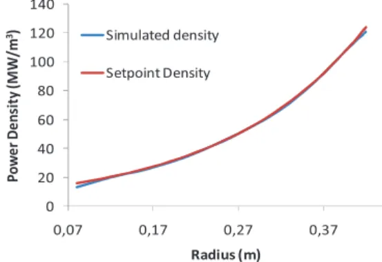
One of the advantages of the multi-phase induction system is its flexibility, that is to say, its ability to face various power density profiles: linear or exponential, rising or downward as shown hereafter. The optimization procedure leads to the inductor currents which are necessary to obtain the corresponding temperature profiles inside the disc. Fig. 10 and 11 show the case of an exponential rising profile. The reference profile and the density calculated by the mathematical optimization procedure in a theoretical way, is plotted in Fig. 10. The corresponding simulation with power electronic supply and the results are shown in Fig. 11. It is easy to see that they are in good agreement.
Fig. 10. Power density calculated with the theoretical procedure In this first study, the aim is to obtain a flat temperature profile. Then, the developped optimization procedure [18][19] leads to the optimal inductor currents, i.e. amplitudes and phase shifts with respect to phase 1, which are listed in Table I.
Fig. 11. Power density simulated with the whole system TABLE I
OPTIMAL SUPPLY INDUCTOR CURRENTS
Source current: Is = 87.9 A Inductor currents
RMS values (A) Phase shifts (°)
I1 253.6
I2 114 #21 -49.4
I3 93 #31 -63.2
III. TEMPERATURE INFLUENCE
The model parameters will change as the temperature increases. This point is far from obvious and only few papers deal with this interesting problem. It could be found in [23] that the metal resistivity increase with the temperature has an outstanding influence on the temperature profile around 700°C, while [24] points out no significant effect but around 250°C in the field of domestic appliances. According to [23] and [24], the obtained simulation results showed that radiation and heat conduction could be neglected below 400°C and that the heating time under the inductors is much shorter than the thermal time constant.
0 0.1 0.2 0.3 0.4 0.5 -15000 -10000 -5000 0 5000 Radius (m) 1 /m f1R f2R f3R Ri 1 /m 2 0 0.1 0.2 0.3 0.4 0.5 -15000 -10000 -5000 0 5000 Radius (m) 1 /m f1R f2R f3R Ri 0 0.1 0.2 0.3 0.4 0.5 -15000 -10000 -5000 0 5000 Radius (m) 1 /m f1R f2R f3R Ri 1 /m 2 4 0 0.1 0.2 0.3 0.4 0.5 -2.5 -2 -1.5 -1 -0.5 0 0.5x 10 4 Radius (m) 1 /m 2 f 1I f2I f3I 4 0 0.1 0.2 0.3 0.4 0.5 -2.5 -2 -1.5 -1 -0.5 0 0.5x 10 4 Radius (m) 1 /m 2 f 1I f2I f3I 0 0.1 0.2 0.3 0.4 0.5 0 2 4 6 8 10 12 14x 10 7 Radius (m) P o w e r D e n s ity ( W /m 3) Setpoint density Calculated density 0 20 40 60 80 100 120 140 0,07 0,17 0,27 0,37 P o w e r D e n si ty (M W /m 3) Radius (m) Simulated density Setpoint Density
Consequently, only convection will be taken into account. Moreover, a kind of compensation between different phenomena can be put in evidence. The material resistivity rises up with temperature and modifies the power density in (5), but the image functions also vary with temperature. As it can be seen in Fig. 10, their modules decrease. Extracted from Flux2D® software, these results show the temperature influence on the real and imaginary parts of the image function of phase 1.
Fig. 12. Real and imaginary parts of the image function of phase 1
IV. OPEN-LOOP EXPERIMENTAL RESULTS
In Fig. 13 experimental and simulated temperatures are presented in an open-loop condition with ten measurement points along the radius of the disc. These profiles depend on the coil characteristics (impedance, positions) and on the supply currents that feed them.
Fig. 13. Simulated and experimental temperature profiles After two minutes heating, the two profiles are quite similar and the difference between them does not exceed 10%, except close to the centre of the piece where it is very difficult to control the heating process and the temperature. At this point, simulating model has to be slightly improved and in order to be compared again with new experimental results.
V. CURRENTCONTROL
A. PI control
As far as we know, very few works deal with the control of this kind of coupled system [15-19]. A first simplified control scheme is proposed. Fig. 14 describes for one phase, the current control loop for the RMS values of the
inductor currents using PI controllers. The RMS current values are calculated by using a passive component circuit composed by a full-wave rectifier and a low-pass filter which bandwidth is set to 100Hz, a kind of trade-off between the bandwidth of the low-pass filter and the bandwidth of the RMS closed loop control.
Fig. 14. RMS current PI control scheme for each of the 3 phases The PI controllers are tuned according to a pole placement method from three second order small signal models (9)-(11), which derive from open loop experiments and with the help of a parameter off-line identification method based on the least mean square method.
'"_]^K acos (_")= 103.8`aKbc (1 + 1.234da$e)# (9) '#_fgh acos(_#)= 131.7`aKbc (1 + 1.292da$e)# (10) '$_]^K acos (_$)= 128.7`aKbc (1 + 1.521da$e)# (11)
The closed-loop bandwidth is set to 100Hz (<1500 Hz) i.e. lower than the open-loop bandwidth and lower than the switching frequency. It is also set lower than the open-loop bandwidth ($300Hz) because the temperature time constant is very large compared with the current dynamics. The reference RMS values are predetermined for a homogeneous temperature profile and they are reached in few periods i.e. few milliseconds after a 20% step input on their references at 40ms, with low overshoot and no steady-state error. It is important to notice that the power electronic stage does not work according to PWM principles. Given that, inverter currents vary only four times per period, the sample frequency is set to 6 kHz, i.e. four times the system frequency [17]. In simulations, a additional unit delay is included in the closed-loop so as to insert a sampling period delay due to the A/D and D/A conversion times and to the calculation time of the firing angles of the switches inside the FPGA. The cos-1 term in Fig.14 allows linearization of the whole loop since the RMS current on inverter n°i is given by (12).
',3/i =jThklm (n0)
op# (12)
Fig. 15 presents the results when sampling the PI controllers under the same conditions as above, with a small reference step at t=40ms. The stability of the inductor currents, proof that it is possible to work with a sampling frequency only four times greater than the supply system frequency. -500 0 500 1000 0 200 400 600 -0.015 -0.01 -0.005 0 temperature °C radius (mm) F 1 r e a l p a rt -500 0 500 1000 0 200 400 600 -0.02 -0.015 -0.01 -0.005 0 temperature °C radius (mm) F 1 i m a g in a ry p a rt 0.1 0.15 0.2 0.25 0.3 0.35 0.4 0.45 0 100 200 300 400
Abscissa along the radius (m)
T e m p e ra tu re ( °C ) simulated profile experimental profile 0.1 0.15 0.2 0.25 0.3 0.35 0.4 0.45 0 100 200 300 400
Abscissa along the radius (m)
T e m p e ra tu re ( °C ) simulated profile experimental profile H(s) K H(z) cos-1 z1 ZOH Ieff PI Image ofIind Ref alpha
Fig. 15. Inductor current and RMS value waveforms on small signal step input in sampling condition with a unit delay
The inverter currents (Iinvi) keep their square waveforms
whereas the outputs of PI-controllers (alphai) are sampled
at 6 kHz (Fig. 16).
Fig. 16. alpha angles and inverter currents during one period in steady state
To be as close as possible to the experimental conditions, a quantization block is added in the simulation model, the quantization part of the 8bit A/D and D/A components.
Fig. 17. Duty cycles (up) and RMS-values (down) of inductor currents in closed loop with quantization
After some transients on the RMS currents in Fig. 17, the inductor currents in Fig. 18 look like the desired waveforms, i.e. sinusoidal curves with the required amplitudes and phases.
Fig. 18. Three phase inductor currents in closed loop with quantization
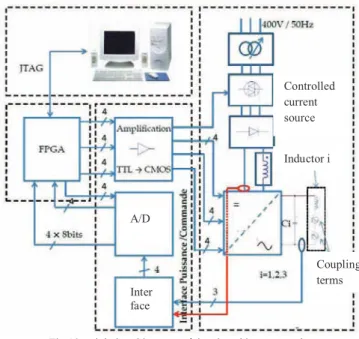
Fig 19 : global architecture of the closed loop control
The three PI controllers are implemented in a FPGA based control system described in Fig. 19 while the corresponding first closed-loop experimental results could be found in Fig. 20. It is important to notice that the PI controllers are implemented in an old FPGA (FLEX10K20 TC144-4 from Altera®) with a very limited number of elements; as a result, some precision problems occur as it can be seen in Fig. 20 with the small oscillations around the steady state. Nevertheless, the 3 phase RMS currents are controlled around their set points, even in case of sudden dc source current changes (blue curve).
0.0 -200.00 -400.00 200.00 400.00 I1 Ref1 Ieff1 0.0 -100.00 -200.00 100.00 200.00 I2 Ref2 Ieff2 40.00 42.00 44.00 46.00 48.00 Time (ms) 0.0 -50.00 -100.00 50.00 100.00 I3 Ref3 Ieff3 20.00 40.00 60.00 80.00
alpha1 alpha2 alpha3
51.75 51.875 52.00 52.125 52.25 52.375 Time (ms) 0.0 -50.00 -100.00 50.00 100.00
Iinv1 Iinv2 Iinv3
25.00 50.00 75.00
alpha1 alpha2 alpha3
20.00 40.00 60.00 Time (ms) 0.0 40.00 80.00 120.00
Ieff1/2 Ieff2 Ieff3 Ref1/2 Ref2 Ref3
62.40 62.80 63.20 63.60 64.00 64.40 64.80 Time (ms) 0.0 -200.00 -400.00 200.00 400.00 I1 I2 I3 "%$ "#$ A/D Inter face Controlled current source Inductor i Coupling terms
Fig. 20. three phase RMS currents (green, yellow and red) and dc source current (blue)
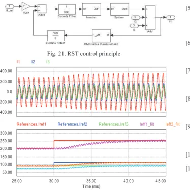
B. RST control
In order to improve the control performance, a RST controller has been designed for each of the 3 phases. Fig. 21 depicts the architecture for one phase, where I12 and I13
are the coupling terms extracted from (1), and describing the effects of current 2 on phase 1 and of current 3 on phase 1 respectively. The corresponding simulation results are presented in Fig. 22. Thanks to the RST properties and to suitable pole placement without any zero in the closed loop transfer function, the transients show no overshoot and the same time response are observed on the 3 phases and then performance in simulation is improved compared to that of the PI controllers.
Fig. 21. RST control principle
Fig. 22. Inductor currents and duty cycles during transients with RST controllers
VI. CONCLUSION
This paper presents a simplified but complete and powerful model of the electrical and thermal behaviour of an induction heating multi-phase system taking into account the coupling effects between the phases and the workpiece. The first open loop experimental results on the temperature profile are in rather good agreement with the simulation results and can be seen as a first step for model validation. The flexibility of this system is an important asset, so digital control makes it possible The first current controllers give rather good closed loop performance in continuous and digital conditions. Future works will tackle the closed-loop control of temperature in the material to be heated, the soft-switching mode for the power electronic stage, the studies are currently in progress. Moreover, the current control itself could be improved with a state space decoupling method which aims at making the inductor currents completely independent of each other whatever the reference point.
REFERENCES
[1] E. Rapoport, Y. Pleshivtseva, “Optimal control of induction heating processes”, CRC/Taylor & Francis, 2006.
[2] S. Zinn, S. L. Semiatin, E. P. R. Institute, “Elements of induction heating: design, control, and applications”, Ed. ASM International. 1988.
[3] T. Tudorache, V. Fireteanu, « Magneto-thermal-motion coupling in transverse flux heating », COMPEL: The International Journal for Computation and Mathematics in Electrical and Electronic Engineering, vol. 27, no. 2, p. 399-407, 2008.
[4] Y. Neau, B. Paya, M. Anderhuber, F. Ducloux, J. Hellegouarch, J. Ren, « High Power (3 MW) transverse flux inductor for industrial heating », in Proceedings of the International Conference EPM 2003, Lyon (France), 2003, p. 570-575.
[5] S. Wang; K. Izaki, I. Hirota; H. Yamashita; H. Omori; M. Nakaoka;
"Induction-heated cooking appliance using new quasi-resonant
ZVS-PWM inverter with power factor correction" , Industry Applications, IEEE Transactions on Volume: 34 , Issue: 4, 1998 , Page(s): 705 - 712
[6] D. Pimentel, M. B. Slima, A. Cheriti, « Power Control for Pulse Density Modulation Resonant Converters », in Industrial Electronics, 2006 IEEE International Symposium on, 2006, vol. 2, p. 1259-1264.
[7] N-J. Park; D-Y Lee; D-S. Hyun; "A Power-Control Scheme With Constant Switching Frequency in Class-D Inverter for Induction-Heating Jar Application", Industrial Electronics, IEEE Transactions on, Volume: 54 , Issue: 3, 2007 , Page(s): 1252-1260 [8] N.A. Ahmed, "High-Frequency Soft-Switching AC Conversion
Circuit With Dual-Mode PWM/PDM Control Strategy for High-Power IH Applications", Industrial Electronics, IEEE Transactions on, Volume: 58 , Issue: 4 , 2011 , Page(s): 1440 - 1448
[9] S. Chudjuarjeen; A. Sangswan; C. Koompai, "An Improved LLC Resonant Inverter for Induction-Heating Applications With Asymmetrical Control", Industrial Electronics, IEEE Transactions on, Volume: 58 , Issue: 7, 2011 , Page(s): 2915 - 2925
[10] O. Fishman et N. Vladimir, « Gradient induction heating of a workpiece », U.S. Patent US 20090314768, December, 2009 [11] P.H. Ha, H. Fujita, K. Ozaki, N. Uchida “Analysis and Control of
the Heat Distribution in a Zone-Control Induction Heating System”, International Power Electronics Conference, 21-24 June 2010, Page(s): 2324-2330
[12] S.O. Fishman, R.K. Lampi, J.H. Mortimer, V.A. Peyshakhovich, «Induction heating device and process for controlling temperature distribution », U.S. Patent WO/2000/028787, may 2000.
[13] H. Fujita; N. Uchida; K. Ozaki; "A New Zone-Control Induction Heating System Using Multiple Inverter Units Applicable Under Mutual Magnetic Coupling Conditions", Power Electronics, IEEE Transactions on Volume: 26 , Issue: 7, 2011, Page(s): 2009–2017 [14] N. Uchida, K. Kawanaka, H. Nanba, K. Ozaki, « Induction heating
0.0 -200.00 -400.00 200.00 400.00 I1 I2 I3 25.00 30.00 35.00 40.00 45.00 Time (ms) 50.00 100.00 150.00 200.00 250.00 300.00
References.Iref1 References.Iref2 References.Iref3 Ieff1_filt Ieff2_filt
Phase and DC source currents (A) (A)
method and unit », U.S. Patent 2007012577107, june 2007. [15] A. Schonknecht, A., R.W.A.A.De Doncker, “Novel topology for
parallel connection of soft-switching high-power high-frequency inverters”, Industry Applications, IEEE Transactions on, Volume: 39 , Issue: 2, 2003 , Page(s): 550 - 555
[16] ; ; J. Acero; ; C. Carretero;
“Multiple-output resonant matrix converter for
multiple-inductive-load systems”, Applied Power Electronics Conference and Exposition (APEC), 2011 Twenty-Sixth Annual IEEE, 2011 , Page(s): 1338 – 1343
[17] O. Lucia; J.M. Burdio; L.A. Barragan; C. Carretero; J. Acero;
"Series Resonant Multiinverter with Discontinuous-Mode Control
for Improved Light-Load Operation ", Industrial Electronics, IEEE Transactions on, Volume: 58 , Issue: 11, 2011 , Page(s): 5163 – 5171
[18] M. Souley, J. Egalon, S. Caux, O. Pateau, P. Maussion, “Modeling and control of a multi phase induction system for metal disc heating,” IECON 2010 - 36th Annual Conference on IEEE Industrial Electronics Society, 2010, p. 562-567.
[19] J. Egalon, S. Caux, P. Maussion, M. Souley, O. Pateau, “Multiphase induction system for metal disc heating: modeling and RMS-value control”, IAS’2011, Orlando, FL, USA
[20] G. Manot, “Modélisation couplées des dispositifs électromagnétiques associés à des circuits d'électronique de puissance. Intégration de la commande des convertisseurs - Aide à la conception d'un dispositifs de chauffage par induction à flux transverse,” PhD thesis, University of Toulouse, France, 2002. [21] M. Souley, A. Spagnolo, O. Pateau, B. Paya, J. Hapiot, P. Ladoux,
P. Maussion, “Characterization methodology for the impedance matrix of multi-coil induction heating device”, 6th International Conference on Electromagnetic Processing of Materials EPM 2009; Dresden, October 19-23, 2009,
[22] M. Souley, P. Maussion, P. Ladoux, O. Pateau, “Simplified model of a metal disc induction heating system,” HES-10, International Symposium on Heating by Electromagnetic Sources, Padua, May 18-21, 2010
[23] M. Zlobina, S. Galunin, Y. Blinov, B. Nacke, A. Nikanorov, et H. Schülbe, "Numerical modeling of non-linear transverse flux heating systems", International Scientific Colloquium, Modeling for Electromagnetic Processing, Hannover, March 24-26, 2003 [24] C. Carretero; J. Acero; R. Alonso; J.M. Burdio; F. Monterde;
"Temperature Influence on Equivalent Impedance and Efficiency of Inductor Systems for Domestic Induction Heating Appliances », Applied Power Electronics Conference, APEC 2007 - Twenty Second Annual IEEE , Page(s): 1233 - 1239
Julie Egalon received the M.S. degree in electrical
engineering from the Institut National Polytechnique de Toulouse, Toulouse, France, in 2009. She is currently working toward the Ph.D. degree at the LAboratoire PLAsma et Conversion d’Energie (LAPLACE), Toulouse. Her research interests include current control methods for the present induction system.
Stéphane Caux was born in 1970, he received his PhD
in Robotics from Montpellier University - France in 1997. Assistant professor at LEEI and LAPLACE since 1998, his main interest concerns robust control and observer for electrical systems (electrical motors, inverters and fuell cell systems) and real time energy management for multi-source electrical systems (optimization, fuzzy management).
Pascal Maussion received the M.Sc. and Ph.D.
degrees in electrical engineering from the Toulouse Institut National Polytechnique, France, in 1985 and 1990, respectively. He is currently a Full Professor at the University of Toulouse, and a Researcher at the Centre National de la Recherche Scientifique Research Laboratory: LAboratoire PLAsma et Conversion d’Energie (LAPLACE), Toulouse. His research activities deal with the control and diagnosis of electrical systems such as power converters, drives and lighting and with the design of experiments for optimization in control and diagnosis. He is currently the Head of the Control and
Diagnosis Research Group of LAPLACE. He teaches control and diagnosis at the University of Toulouse.
Majid Souley received the electromechanical engineer
degree at Ecole des Mines in Niamey, Niger in 2004, M.Sc. and PHD degrees in electrical engineering from université Le Havre and Institut National Polytechnique de Toulouse in 2007 and 2011 respectively. Since 2011, he worked in aerospace industry, especially on the development of Aircraft electrical systems.
Olivier Pateau received theelectrical engineer degree
from the Conservatoire National des Arts et Métiers, France, in 2004. He worked at EDF R&D since 1996, in the field of induction heating in industry (modeling, design, testing, …).