To cite this document: Bousquet, Yannick and Dufour, Guillaume and Carbonneau, Xavier and Trébinjac, Isabelle and Roumeas, Mathieu Description of the unsteady flow pattern from peak efficiency to near surge in subsonic centrifugal compressor stage. (2013) In: 10th European Turbomachinery Conference - ETC10, 15-19 Apr 2013, Lappeenranta, Finland.
O
pen
A
rchive
T
oulouse
A
rchive
O
uverte (
OATAO
)
OATAO is an open access repository that collects the work of Toulouse researchers and makes it freely available over the web where possible.
This is an author-deposited version published in: http://oatao.univ-toulouse.fr/
Eprints ID: 9045
Any correspondence concerning this service should be sent to the repository administrator: [email protected]
Description of the unsteady flow pattern from peak efficiency to near
surge in a subsonic centrifugal compressor stage
Y. Bousquet* - X. Carbonneau* - G. Dufour* - I. Tr´ebinjac** - M. Roumeas***
*Universit´e de Toulouse, ISAE 10, avenue Edouard Belin BP 54032
31055 Toulouse Cedex 4 France
[email protected] - [email protected] - [email protected] **Laboratoire de M´ecanique des Fluides et d’ Acoustique
UMR CNRS 5509 Ecole Centrale de Lyon, UCBLyon I, INSA 36 av. Guy de Collongue, 69134 Ecully Cedex,
France
[email protected] ***Liebherr-Aerospace Toulouse SAS
408 Avenue des Etats Unis 31016 Toulouse
ABSTRACT
This paper aims to describe the flow structure modifications when the operating point moves from peak efficiency to near stall condition in a moderate pressure ratio centrifugal compressor stage consisted of a splittered unshrouded impeller and a vaned diffuser. The investigations are based on three-dimensional U-RANS simulation results. The flow is described in the impeller and in the vaned diffuser through time-averaged flow quantities and unsteady fluctuations. Re-sults show that at low mass flow rate, the effects of secondary flow in the impeller are more pronounced, inducing both, high time-averaged values and temporal fluctuations of the flow angle near the shroud at the diffuser inlet, leading to vane suction side boundary layer sepa-ration. Pressure waves due to impeller diffuser interaction spread through the vaned diffuser generating unsteadiness which intensifies at near surge condition.
NOMENCLATURE Latin Letters
˙
m mass flow rate (kg/s) MB, SB main blade, splitter blade
p pressure (pa) r radius (m)
PE, NS peak efficiency, near surge t time
U impeller speed (m/s) T time period
V absolute velocity (m/s)
W relative velocity (m/s)
Greek Letters
α flow angle Ω rotation speed
Subscripts and Superscipts
0 total variable m,r,t meridional, radial, tangential
1 impeller inlet cor corrected value
2 impeller exit ref reference variable
3 diffuser inlet R/S rotor, stator
Introduction
Centrifugal compressors for the aeronautical industry have to simultaneously achieve high pres-sure ratio and high efficiency at design operating point, while minimizing the element size. In this context the trend has been toward high speed impeller associated with a vaned diffuser to achieve high pressure recovery in a reduced space. Nowadays, through the objectives of ACARE 2020, they are also required to operate over a large range of mass flow rates with an acceptable efficiency. At low mass flow rates, where generally the maximum pressure ratio is reached, the compressor system sta-bility is limited by the onset of instasta-bility known as rotating stall and surge phenomena. Rotating stall is characterized by the presence of one or several cells rotating around the annulus. Surge exhibits large amplitude oscillations of pressure through the compressor system (Greitzer (1976)).
The extend of the operating range of the compression system involves major interests. Impeller with outlet backsweep angle are widely used in the industry to increase the stability of the impeller and finally the stability of the stage (Cumpsty (2004)). Nevertheless at constant radius and rotation speed, the impeller work is therefore decreased and inherently the pressure ratio of the stage. Efforts have also been dedicated to flow control in order to delay the emergence of instability. Different efficient techniques are presented in Skoch (2003) in a high speed centrifugal compressor. However, the use of stabilization techniques to extend the operating range requires a good comprehension of the flow mechanisms leading to stall inception.
Surge phenomena in centrifugal compressors have been studied for almost sixty years. However, due to the various configurations found in the literature, a large spectrum of stall and surge behavior is reported and up to now, no overall rule can be given a priori concerning the instability inception in a given machine. For example, the experimental work of Emmons et al. (1954) in a low pressure ratio centrifugal impeller with a vaneless diffuser shows that rotating stall occurs in the inducer prior to the surge onset. In high pressure ratio centrifugal compressor, Spakovszky and Roduner (2009) has measured backward rotating stall waves in the vaneless space leading to surge. The study of Toyama et al. (1977) reports oscillations of total and static pressure in the vanesless space before the surge onset. Tr´ebinjac et al. (2011) described a surge inception resulting from a massive separation of the suction side boundary layer in the vaned diffuser of a transonic compressor stage.
Most of the available data come from experimental investigations because reliable numerical re-sults concerning the instability onset were unattainable (and still difficult to obtain). The description of the flow behavior is thus partial at best. In this context, effort in numerical investigation is neces-sary and promising in order to reach complementary knowledge on the surge inception. In addition, the usual configurations found in the literature concern high pressure ratio compressors (generally above 5) with vaned diffuser operating at transonic condition, or low pressure ratio compressors us-ing vaneless diffuser. The present paper deals with a fully subsonic centrifugal compressor stage, with a vaned diffuser, reaching a 2.5 pressure ratio. In the first part of the paper, the test case and the nu-merical procedure are briefly described. Then, the impeller flow structure is investigated considering time-averaged flow quantities. Finally, unsteady effects are analysed in the vaned diffuser.
Test case and numerical procedure
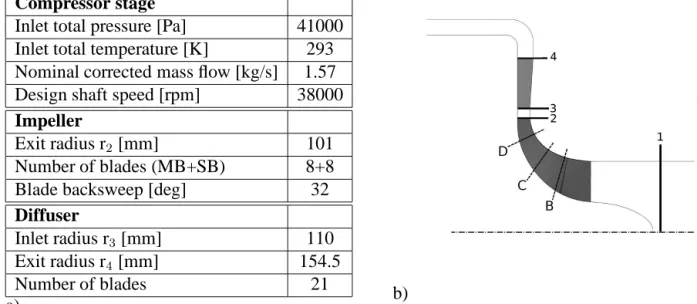
The centrifugal compressor stage was designed by Liebherr-Aerospace Toulouse SAS and is in-tegrated in an air-conditioning system. The stage is composed of a backswept splittered unshrouded impeller, a vaned diffuser with wedge blades and a volute. The design specification is based on a stage static-to-total pressure ratio of 2.5 with a design rotation speed of 38000 rpm. The main specifications of the compressor stage are given in the Table of the figure 1.a.
Steady and unsteady computations were performed using the commercial code ’NUMECA FINE Turbo’ solving the three dimensional Reynolds-Averaged Navier-Stokes equations based on a cell-centered finite volume approach on structured grids. The spatial discretization is a central scheme
Compressor stage
Inlet total pressure [Pa] 41000 Inlet total temperature [K] 293 Nominal corrected mass flow [kg/s] 1.57 Design shaft speed [rpm] 38000
Impeller
Exit radius r2 [mm] 101
Number of blades (MB+SB) 8+8
Blade backsweep [deg] 32
Diffuser
Inlet radius r3[mm] 110
Exit radius r4 [mm] 154.5
Number of blades 21
a) b)
Figure 1: (a) Test case specification; (b) Meridional vue of the compressor stage
with a Jameson type dissipation using 2nd and 4th order derivatives of the conservative variables. Considering the steady simulations, the equations are advanced in pseudo time with an explicit four-stage Runge-Kutta scheme. Conventional techniques as multigrid method, local time step, IRS (Im-plicit Residual Smoothing) are used to speed-up the convergence of the simulations to the steady state. For the unsteady simulations, the dual time stepping approach has been used. At each physical time step, a steady state problem is solved in a pseudo time. The turbulence model used to perform the simulations is the single-equation Spalart-Allmaras (Spalart and Allmaras (1994)).
The computational domain begins 40mm upstream the inlet bulb, contains the centrifugal impeller, the vaneless space, the vaned diffuser and ends with a90oturning pipe used as a computational buffer
zone to damp possible reflections from the exit boundary condition. The volute is not taken into consideration in the calculation model. A meridional view of the compressor stage is sketched in figure 1.b.
The structured grid was generated with Autogrid V5. In order to obtain mesh independent results, the parameters to generate the mesh resulted from an earlier study (Dufour et al. (2004)), which was performed in the same configuration. Then, the size of the first cell is set to 3µm and leads to y+< 3
near wall regions. The impeller main blade and splitter blade grid consist of 89 points in the spanwise direction including 29 points in the gap region, 92 points in the pitchwise direction and 161 points in the streamwise direction. The diffuser blade contains 57 points in the spanwise direction, 119 points in the pitchwise direction and 121 points in the streamwise direction. The inlet domain, the impeller and the diffuser include respectively 0.132, 2.598 and 1.7 millions nodes.
Considering the boundary conditions, the total pressure, the total temperature and flow angles are prescribed at the domain inlet. For the outlet condition, static pressure is imposed with a radial equilibrium allowing pressure gradient in the radial direction. For all the walls, an adiabatic and no-slip condition is imposed.
To perform the unsteady simulations, due to impeller and diffuser blade numbers, the geometry scaling method is not possible without changing the blade numbers. Consequently, the phase lagged-approach (chorochronic method) has been used as accurate results have already been showed in Bulot et al. (2009) over the whole operating range, in a transonic centrifugal compressor. This method enables the calculation domain reduction to one single blade passage while considering the effects of the impeller displacement. In other words, the phase-lagged technique supposes that unsteady effects
are only due to the movement of the wheel. Then, the flow is time-periodic in the frame of reference of the row and a phase-lag relation exists between two adjacent channels.
Considering the unsteady parameters, the number of physical time steps per impeller main blade passing period has been set to336, which is equivalent to 2688 time steps to complete a full rotation
(the impeller has 8 main blades). Then the stator temporal period is discretized into336 time steps,
while the impeller temporal period is discretized into 128 time steps (the diffuser has 21 blades).
All simulations were performed at the design rotation speed. Steady simulations have also been per-formed all over the operating range while unsteady simulations consider the peak efficiency operating point and a near surge operating point. To obtain the near surge operating point, the outlet pressure has been slightly increased step by step until the simulation diverges. It means that the given re-sults correspond to the last converged case. Considering the CPU time, a steady simulation needs 2000 iterations to obtain good convergence, while one unsteady simulation requires approximately 12 complete impeller rotations, leading to 200000 iterations.
Overall performances 1.4 1.45 1.5 1.55 1.6 1.65 1.7 2.25 2.3 2.35 2.4 2.45 2.5 2.55 2.6 2.65 RANS U−RANS
Corrected Mass F low[kg/s]
P re ss u re R a ti o (Stage) a) 1.4 1.45 1.5 1.55 1.6 1.65 1.7 1 1.1 1.2 1.3 1.4 1.5 1.6 1.7 1.8 1.9 RANS U−RANS
Corrected Mass F low[kg/s]
P re ss u re R a ti o (Impeller)
(V aned Dif f user) (V aneless Space)
b)
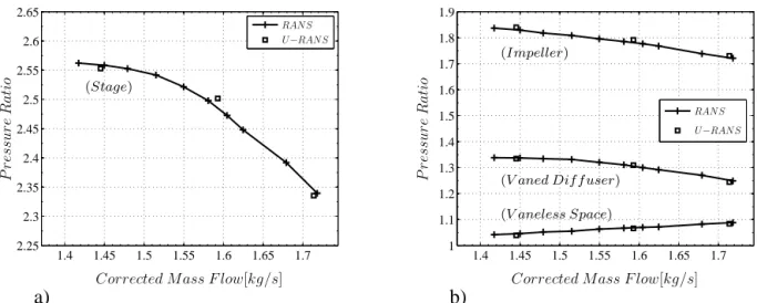
Figure 2: (a) Performance of the compressor stage; (b) Performance of the decoupled components Figure 2.a gives the static-total pressure of the stage as a function of the corrected mass flow for steady and unsteady simulations results. The data coming from the unsteady simulations are time-averaged. The absolute total pressure is mass weighted averaged at plane 1 and the outlet static pressure is extracted with a scalar averaged extracted at plane 4 (see figure 1.b). As it was already shown in Bousquet et al. (2012), on this configuration, overall performance is correctly predicted by the steady simulation. According to Greitzer (1981), the compressor may exhibit static or dynamic instability when the compressor operates on the positive slope. In other words, the peak of the char-acteristic may be considered as a convenient working approximation for the stall or the surge point. It is then interesting to evaluate the contribution of all the components to the overall stability by segre-gating the total-to-static pressure ratio of the stage into the product of the individual performance of the impeller, vaneless space and vaned diffuser.
Figure 2.b shows the static-to-total pressure ratio of the impeller, static-to-static pressure ratio of the vaneless space and static-to-static pressure ratio of the vaned diffuser. The impeller slope is negative all over the operating range and contribute to maintain the system stability. Considering the vaneless space, as expected, the slope is slightly positive because the blockage rises as the mass flow is reduced. Then the vaneless space contributes to destabilize the system. However, the slope is slight and then the contribution is moderated. Finally, the static-to-static pressure ratio of the vaned diffuser
(semi vaneless space + vaned diffuser) has a negative slope over the major part of the operating range. As shown by Hunziker and Gyarmathy (1994), the semi-vaneless space is a zone highly stabilizing. However, while the mass is reduced the slope decerases and for operating points near the stability limit the gradient almost vanishes while the slope of the impeller still rises. Therefore, in such a situation it may be thought that the loss of stability comes from the deterioration of the flow in the semi-vaneless space which losts its stability effect.
Investigation of the flow in the impeller
In the major part of the impeller, a steady behavior has been noticed. Unsteadiness due to diffuser potential effects, affects mainly the last 5% of the impeller blade chord. Therefore, the impeller flow is analysed considering time-averaged unsteady simulation results at peak efficiency (PE) and near surge (NS) operating point.
Analysis of the flow structure
Due to multiple curvatures and rotation effects, the main flow in centrifugal impeller is affected by secondary flows. As stated by Eckardt (1976), the presence of secondary flow in the impeller are in major part responsible of the jet-wake structure classically observed in centrifugal impeller.
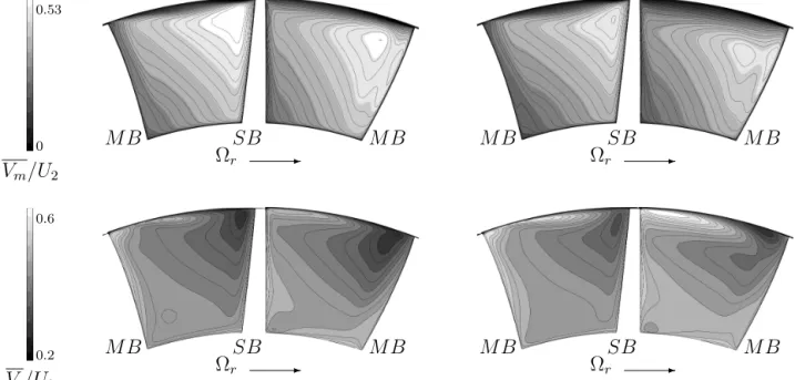
0.53 0 Vm/U2 SB MB MB -Ωr SB MB MB -Ωr 0.6 0.2 Vt/U2 SB MB MB -Ωr SB MB MB -Ωr
Figure 3: Reduced, time-averaged, meridionnal and tangential velocity at section C for PE (left) and NS (right) operating point
From PE to NS condition, the mass flow reduction leads to a decrease of the meridional velocity and an increase of the tangential velocity level, as seen in the figure 3. For both operating points, the secondary flows are noticeable by the low meridional velocity zones, near the shroud region. Due to the meridional curvature, low momentum flows from blade boundary layers migrate toward the shroud. At the tip of the blade, they are transported by leakage flow effects toward the pressure side of the adjacent blade. Therefore, the low meridional velocity zones are feed by the secondary flows including leakage flows. As main blade leakage flow is more intense than splitter blade leakage flow, there is more low meridional velocity flow in the right channel. Comparing the two operating points, secondary flow effects are more pronounced at NS condition. This is all the more noticeable in the right channel.
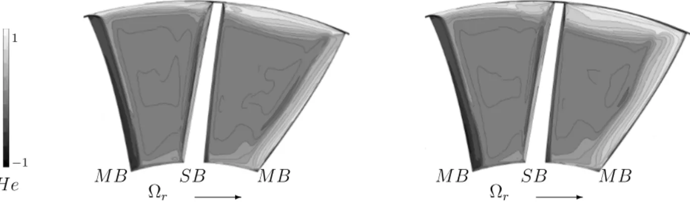
1 −1 He MB SB MB -Ωr SB MB MB -Ωr
Figure 4: Time-averaged helicity at section B for PE (left) and NS (right) operating point
-Ωr Ωr
-Figure 5: Streamline representation from main blade suction side boundary layer for the PE (left) and NS operating point (righ)
The transport phenomena in the impeller can be described in term of vortical structures. Figure 4 shows the time-averaged helicity at section B (see figure 1.b) for both operating points. Vortices due to the meridional curvature effect are visible near the main blade boundary layer, and are responsible of the low momentum flow transport toward the shroud. It can be noticed that the mass flow reduction induces an intensification of the vortex in the suction side main blade. Therefore, the flow transport toward the tip of the blade is more effective, as it can be seen in the figure 5 representing the stream-lines near the main blade suction side boundary layer, at 50% span, from the leading edge to 35% of the blade chord. In addition, the mass flow reduction leads to an increase of the incidence angle at the impeller blade leading edge. In the study case, at NS condition, boundary layer separation occurs on the main blade suction side. The low momentum flow associated to the separation zone is transported toward the shroud (figure 5) and contributes to accentuate the excess of low meridional velocity flow, in the right channel, noticed at NS condition (figure 3).
In summary, moving from PE to NS does not change the overall flow structure. Nevertheless, secondary flows effects are more pronounced leading to the extend of the low meridional velocity zones, visible from the impeller highest curvature part up to the impeller exit.
Analysis of impeller exit flow
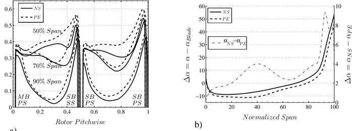
As seen in the figure 6.a, the impeller flow exit is highly distorted in the pitchwise direction. The distortion is all the more accentuated near the shroud due to leakage flow effects. In shrouded impeller, the position of the wake is determined by the Rossby number. In unshrouded impeller, leakage flows play a dominant role in the jet-wake structure as they transport the wake toward the pressure side of
0 0.2 0.4 0.6 0.8 1 0 0.1 0.2 0.3 0.4 0.5 0.6 NS P E Rotor P itchwise Vr /U 2 90% Span 70% Span 50% Span M B P S SB SS SB P S SB P S a) 0 20 40 60 80 100 −10 0 10 20 30 40 50 60 0 20 40 60 80 1000 2 4 6 8 10 α −α NS NS P E P E Normalized Span ∆ α = α − αB la d e ∆ α = αN S − αP E b)
Figure 6: (a) Pitchwise distribution, of the reduced radial velocity at 50%, 70% and 90% span; (b) Spanwise distribution of the flow angle
the passage. In the right channel, main blade leakage flows effects dominate the rotation effects and move the wake toward the pressure side of the splitter blade. In the left channel, splitter blade leakage flow effects are weaker, and rotation effects dominate. Therefore, the wake is located near the splitter blade suction side. Considering the two operating points, as expected, the radial velocity deficit in the wake is larger at NS condition at 50%, 70% and 90% span.
However, despite these circumferential distorsions, the studies of Deniz (2003) and Deniz et al. (2000), lead to the conclusion that the diffuser performance is mainly determined by the axisymmetric time-averaged inlet flow angle. Figure 6.b shows the axisymmetric time-averaged incidence angle at the impeller exit for the two operating points. Diffuser vane angle is constant from hub to shroud. Due to shroud and hub curvatures, the flow is decelerated and the boundary layer thickness increases on the convex shroud surface although a transfer of flow toward the concave hub side induces a radial velocity increase. Therefore, from hub to 85% span, the flow angle naturally increases while above 85% span, due to secondary flows effects, the incidence angle rudely increase until the shroud.
Regarding the two operating points, from hub to 85% span, the shift observed in the incidence angle is bellow4o and is linked to the mass flow reduction. Nevertheless, as stated earlier, secondary
flows are more intense at NS condition. Consequently, above 85% span, an excess of the incidence angle is noticed compared to PE condition and reaches9o. The stability is affected when the incidence
angle becomes positive (α − αBlade > 0), leading to the possibility of boundary layer separation in
the diffuser vane suction side. As the mass flow is reduced, the part of the span in that situation significantly increases and goes from 80-100% of the span to 70-100% of the span (see figure 6.b).
From this part, it has been noted that the flow distortion at the impeller exit significantly accentu-ates as the mass flow is reduced. Therefore, diffuser has to operate with a more distorted flow.
Investigation of the flow in the diffuser
In the vaneless space, a mixing process occurs and trends to uniform the impeller exit flow. Even though, the size of the vaneless space (radial gap) is often not sufficient to allow a complete unifor-mity. Then, due to the rotation speed, impeller exit distortions in the pitchwise direction generate temporal fluctuations at the diffuser inlet by change of frame.
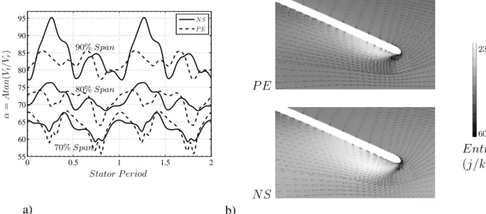
As an example, figure 7.a shows the flow angle value at the diffuser inlet radius, mid pitch and for different spanwises, during two impeller main blade passages. The wakes in the impeller right and left channels produce an increase of the incidence angle. Then, high flow angle values are visible at
0 0.5 1 1.5 2 55 60 65 70 75 80 85 90 95 NS P E Stator P eriod α = A ta n (V t /V r ) 90% Span 80% Span 70% Span a) P E NS b) 230 60 Entropy (j/kg)
Figure 7: (a) Temporal evolution of flow angle in the vaned diffuser inlet at mid-pitch; (b) Time averaged, velocity vector with entropy contour map at 90% span
0.25Ts and at0.75Tsat 90% span. At 70% and 80% span, the level of fluctuation is nearly identical
for the two operating points. Nevertheless, at 90% span, the fluctuation level for the NS operating point is significantly higher and the flow angle value exceed90o (reverse flow occurs). Consequently,
as seen in the figure 7.b, the separation zone on the suction side main blade significantly extends. As shown by Everitt and Spakovszky (2011), flow separation at the diffuser vane leading edge and radial reverse flow near the shroud are some flow features leading to vaned diffuser instability.
50% Span 90% Span
4000
−3000
∆p = pN S− pP E
Figure 8: Rate of static pressure change
In the vaned diffuser, the mass flow reduction leads to a blockage rise in the diffuser channel. Then, the major part of the pressure rise is realized in the entry zone (semi-vaneless space) at NS condition, while at PE condition, the pressure rise is more gradual and occurs in the semi-vaneless space and in the diffuser channel. Figure 8 shows the time-averaged static pressure difference between the NS and PE operating points at 50% and 90% span. At 50% span, the pressure difference increases significantly in the semi-vaneless space until the throat section, showing that the pressure gradient is higher in the entry zone, at NS condition. At 90% span, the separation zone on a diffuser vane suction side alters the flow structure and leads to a deficit of static pressure.
Finally, as the mass flow is reduced, the pressure rise in the vaned diffuser entry zone increases, while the suction side separation zone extends and inherently deteriorate the flow. As shown by Hunziker and Gyarmathy (1994), the semi-vaneless space is a zone highly stabilizing. Therefore, instability may occurs when the separation zone size reaches a limit, preventing the pressure rise in
the diffuser entry zone. P E NS 0.02 0.01 p′ /p
Figure 9: Level of unsteadiness, at 50% span
N S t = 0.0476Ts P E t = 0.0476Ts N S t = 0.0952Ts P E t = 0.0952Ts N S t = 0.142Ts P E t = 0.142Ts 4500 −4500 p′
Figure 10: Pressure fluctuation contours, at 50% span for different time steps
The interactions between the impeller and the diffuser are sources of unsteadiness in the vaned diffuser. Tr´ebinjac et al. (2009) shows in a high speed centrifugal compressor significant unsteadiness in the rear part of the impeller, in the vaneless space, and in the vaned diffuser. Figure 9 shows the level of unsteadiness, at 50% span for the two operating points. It is determined as follow :
p(x, y, z, t) = p(x, y, z, t) + p′(x, y, z, t) (1)
p′ = |p′(x, y, z, t)| (2)
The two operating points show unsteadiness in the diffuser entry zone. On the suction side, only part of the surface is affected by significant unsteadiness at PE condition while at NS condition unsteadiness are present all over the suction side surface.
On the pressure surface side, the level of unsteadiness is approximately constant from the leading edge to the trailing edge for the PE operating point. At NS condition, fluctuation are clearly notice-able, in the last 40% of the chord. This unsteadiness are in part generated by the impeller diffuser interaction inducing pressure waves. The figure 10 illustrates the pressure fluctuation coutour maps, in the diffuser, at 50% span, for different time steps for the two operating points. At NS condition, pressure waves can be viewed at t = 0.0476Ts by negative and positive pressure fluctuations
up-stream the throat section. The level of unsteadiness clearly increases from PE to NS, notably on the vane suction side.
Conclusion
Unsteady numerical simulations were performed in a subsonic centrifugal compressor stage. The impeller and the vaned diffuser flow structure were analyzed at two operating points (peak efficiency
and near surge) thanks to both time-averaged and time-dependent results. The mass flow reduction generates an intensification of the vortical structures in the impeller. The secondary flows effects are consequently more pronounced inducing a significant rise of the flow angle values at the impeller exit, near the shroud. In the vaned diffuser, the pressure gradient increases in the diffuser entry zone. Therefore, the high incidence angle associated to the adverse pressure gradient lead to a separation of the suction side boundary layer.
Acknowledgements
The authors would like to express their thanks to Liebherr Aerospace Toulouse S.A.S for support-ing the present research project.
REFERENCES
Bousquet, Y., Carbonneau, X., and Tr´ebinjac, I. (2012). Assessment of steady and unsteady model predictions for a subsonic centrifugal compressor stage. Proceeding of ASME Turbo Expo,
GT2012-68567.
Bulot, N., Tr´ebinjac, I., Ottavy, X., Kulisa, P., Halter, G., Paoletti, B., and Krikorian, P. (2009). Ex-perimental and numerical investigation of the flow field in a high-pressure centrifugal compressor impeller near surge. J. Power and Energy, 223.
Cumpsty, N. (2004). Compressor Aerodynamics. Pearson Education.
Deniz, S. (2003). Effects of inlet flow field conditions on the stall onset of centrifugal compresso vaned diffusers. Proceeding of IMECE (International Mechanical Engineering congress).
Deniz, S., Greitzer, E. M., and Cumpsty, N. A. (2000). Effects of inlet flow field conditions on the performance of centrifugal compressor diffusers: Part 2-straight-channel diffuser. Journal of
Turbomachinery, 122.
Dufour, G., Carbonneau, X., Arbez, P., and Cazalbou, J. B. (2004). Mesh-generation parameters influence on centrifugal-compressor simulation for design optimization. Proceeding of the 2004
ASME Heat Transfert/FLuids Engineering Summer Conference.
Eckardt, D. (1976). Detailed flow investigations within a high speed centrifugal compressor impeller.
Transaction of the ASME, pages 390–402.
Emmons, H. W., Pearson, C. E., and Grant, H. P. (1954). Compressor surge and stall propagation. page 455.
Everitt, J. N. and Spakovszky, Z. S. (2011). An investigation of stall inception in centrifugal com-presso vaned diffusers. Proceeding of ASME Turbo Expo, GT2011-46332.
Greitzer, E. M. (1976). Surge and rotating stall in axial flow compressors. ASME Journal of
engi-neering power, 98:199.
Greitzer, E. M. (1981). The stability of pumping systems - the 1980 freeman scholar lecture. Journal
of Fluids Engineering, 103:193.
Hunziker, R. and Gyarmathy, G. (1994). The operational stability of a centrifugal compressor and its dependence on the characteristics of the subcomponents. Transactions of the ASME, 116:250.
Skoch, G. J. (2003). Experimental investigation of centrifugal compressor stabilization techniques.
Transactions of the ASME, 125:704.
Spakovszky, Z. S. and Roduner, C. H. (2009). Spike and modal stall inception in an advanced tur-bocharger centrifugal compressor. Journal of Turbomachinery, 131.
Spalart, P. R. and Allmaras, S. R. (1994). A one-equation turbulence model for aerodynamic flows. Toyama, K., Runstadler, P. W., and Dean, R. C. (1977). An experimental study of surge in centrifugal
compressors. Journal of fluid engineering, page 115.
Tr´ebinjac, I., Bulot, N., Ottavy, X., and Buffaz, N. (2011). Surge inception in a transonic centrifugal compressor stage. Proceeding of ASME Turbo Expo 2011.
Tr´ebinjac, I., Kulisa, P., Bulot, N., and Rochuon, N. (2009). Effect of unsteadiness on the performance of a transonic centrifugal compressor stage. Journal of Turbomachinery, 131.