• Aucun résultat trouvé

Effects of the shock duration on the response of CFRP composite laminates

N/A
N/A
Protected

Academic year: 2021

Partager "Effects of the shock duration on the response of CFRP composite laminates"

Copied!
9
0
0

Texte intégral

(1)

Science Arts & Métiers (SAM)

is an open access repository that collects the work of Arts et Métiers Institute of Technology researchers and makes it freely available over the web where possible.

This is an author-deposited version published in: https://sam.ensam.eu Handle ID: .http://hdl.handle.net/10985/9083

To cite this version :

Elise GAY, Laurent BERTHE, Michel BOUSTIE, Michel ARRIGONI, Eric BUZAUD - Effects of the shock duration on the response of CFRP composite laminates - Journal of Physics D : Applied Physics - Vol. 47, p.455303 (8pp) - 2014

Any correspondence concerning this service should be sent to the repository Administrator : archiveouverte@ensam.eu

(2)

1. Introduction

In a context of rising use of composite materials, the assess-ment of their strength is a key issue for the aircraft industry. A proof-test using short shocks has been set up to verify the adhesion between plies (Perton et al 2011, Arrigoni et al 2014, Gay et al 2014). It has the ability to generate a cali-brated tension within a target: peak tension occurs when the tensile waves meet and reinforce each other. The location of this stress depends on the duration of the shock, on the sample properties and thickness.

Relatively few studies describe the application of laser-induced shocks to CFRP composites: Gupta has investi-gated the adhesion test between plies (Gupta et al 1996) and between the fibres and their matrix (Yu and Gupta 1998).

Gilath has studied the response of unidirectional CFRP com-posites to a laser-induced shock (Gilath et al 1990, 1993). The SATAC program (Shock Adhesion Test for Adhesively Bonded Composites) aimed to study the composites behav-iour at very high strain rate in order to verify their adhesion (Perton et al 2011, Ecault et al 2013, Gay et al 2013, 2014). However, the response of composites in the fs regime, as well as the effects of the shock duration on these materials, have never been reported.

In this context, this work reports the development effort to characterize the response of aerospace-grade CFRP laminates to a shock load normal to the fibre direction (out-of-plane). The effects of the shock duration are particularly investigated in this study. The impacts are induced by ultra-short laser pulses (300 fs and 9 ns pulse duration at Full Width at Half

Effects of the shock duration on the

response of CFRP composite laminates

Elise Gay1, Laurent Berthe1, Michel Boustie2, Michel Arrigoni3 and

Eric Buzaud4

1 Laboratoire Procédés et Ingénierie en Mécanique et Matériaux (CNRS), Arts et Métiers ParisTech, 151

bd de l’Hôpital, 75013 Paris, France

2 Département Physique et Mécanique des Matériaux, Institut Pprime (CNRS) ENSMA, 1 av. Clément

Ader, 86960 Futuroscope cedex, France

3 Laboratoire Brestois de Mécanique et des Systèmes EA 4325, ENSTA-Bretagne, 2 rue François Verny,

29806 Brest cedex 9, France

4 CEA Gramat, 46500 Gramat, France

E-mail: elise.gay@hotmail.fr

Abstract

Shock loads induce a local tensile stress within a sample. The location and amplitude of this high strain rate stress can be monitored respectively by the duration and intensity of the shock. The process is applied to carbon fibre reinforced polymer (CFRP) composites, involved in aeronautic or defense industry. This paper describes the response of CFRP laminates of different thicknesses to a shock load normal to the fibres direction. The effects of the shock duration on the wave propagation are key issues of this work. Experiments have been performed on high power laser facilities and on a high power pulsed generator to get a wide range of pulse duration from fs to µs. Numerical simulation provides a comprehensive approach of the wave propagation and tensile stress generation within these complex materials. The main result concerns the relation between the load duration, the tensile stress and the induced delamination within 1, 4 and 8 ply composite laminates.

Keywords: CFRP composite, shock wave, load duration, nanosecond laser, femtosecond laser, GEPI, dynamic delamination

E Gay et al Printed in the UK 455303 JPD © 2014 IOP Publishing Ltd 2014 47

J. Phys. D: Appl. Phys.

JPD

0022-3727

10.1088/0022-3727/47/45/455303

Papers

45

Journal of Physics D: Applied Physics IOP

(3)

Maximum, FWHM) and by a pulsed power generator (450 ns load duration), with a strain rate of about 107, 106 and 104 s−1,

respectively. A finite-element analysis enables to understand the wave propagation and attenuation, and the tensile stress generation within these multilayered materials. The study investigates two major points: the effects of the shock dura-tion and sample thickness on the wave propagadura-tion, and the induced delamination. The goal is to set up a data base that could be used to evaluate the response of a composite within the analyzed range.

This article is divided in 6 sections. Section 2 describes the CFRP laminates involved in this study. The next section intro-duces the stress generation using laser-induced shock and the experimental and numerical configuration. The effects of both load duration and sample thickness on the composites are studied in section 4. A discussion concludes this article.

2. CFRP laminates

CFRP composites are extensively used in modern aircraft structures due to their high strength-to-weight ratio. The materials chosen in this study are CFRP laminates manufac-tured using the carbon fibres G40-800-24K reinforced epoxy Cytec® 5276-1. They are representative of industrial

applica-tions in aeronautic field. Baseline samples are 1, 4 and 8 ply laminates with a lay-up sequence of respectively [0/90°]S and

[0/-45/90/45°]S, their approximate thickness is 170, 650 and

1300 µm. Samples from the same batch are cut to 15  ×  15 mm specimens.

The average diameter of the carbon fibres is 5 µm, their volume ratio is 0.7. A 30 µm thick interply provides adhesion between plies. This epoxy layer is also observed at the surface of the laminate.

The samples are represented in the models by oriented plies between thin epoxy layers, with properties given in table 1. The layers thickness (considered constant) is meas-ured on the laminates cross-sections. Their dynamic behav-iour is described using an elastic law (Parga-Landa et al 1999, Zaretsky et al 2004). The homogenized wave sound velocity C0 in the transverse direction of the laminate is estimated at

2880  ±  20 m s−1. The acoustic impedance Z is defined as the

product of the density and sound velocity.

3. Tensile stress generation using shock load 3.1. Principle of tensile stress generation

A high intensity shock drives a compression wave within the impacted specimen, followed at the end of the load by a

release wave that relaxes the material to its initial state. This pulse propagates through the sample thickness to the oppo-site surface, where it is reflected back as a tensile wave. For homogeneous materials, the maximum tension is obtained when this tensile wave is no more superimposed with the inci-dent compressive wave. It is thus located at a distance of ½ C0 × τload from the back surface (Antoun et al 2003), where

τload is the load duration of the pulse. It is then possible to

locate this stress. It is able to delaminate the sample at a sub-surface location, depending on its amplitude and duration and on the sample properties.

This stress can be used to load locally the interface between two layers and to verify the bond strength. A strong interface will remain unaffected under a calibrated load whereas a weak one will fail. The delamination threshold is estimated by subjecting similar samples to a shock. The load is gradu-ally increased until a disbond is detected. The dynamic tensile strength is then evaluated based on numerical simulations of the experiments.

Each compressive wave reaching the back surface acceler-ates it, the arrival of a tensile wave induces a deceleration. The back surface velocity is thus characteristic of the wave propagation.

Unlike isotropic materials, the wave propagation in com-posite laminates is complex. Between each layer of the laminate, the stress wave is both transmitted and reflected depending on the impedance mismatch at the interface (Abrate 1998, Parga-Landa et al 1999, Datta 2000). The material anisotropy also affects the wave propagation and the shock-induced damage (De Rességuier et al 2005, Millett et al 2007, Ecault et al 2013).

3.2. Experimental configuration

Experiments have been achieved on laser facilities and on a pulsed power generator. A typical experimental set-up is given schematically in figure 1(a). High power lasers deliver a cali-brated pulsed beam, that is focused on a sacrificial overlay (black paint, Fox 1974). The irradiated surface is rapidly vaporized into a high pressure plasma, inducing a compres-sive stress wave in the sample. In the fs regime (ELFIE, LULI, Ecole Polytechnique, 1.057 µm wavelength, 30 J energy), the very short shock wave is subjected to a strong attenuation during its propagation and its duration can be extended up to a ns, see more details in (Sano et al 2008, Cuq-Lelandais 2010). In the ns regime (PIMM, Arts et Métiers ParisTech, 0.532 µm wavelength, 1.5 J energy), a thin water overlay confines the plasma in order to increase the load amplitude and duration (Fabbro et al 1990, Berthe et al 1997).

Table 1. Material properties (T for transverse, L for longitudinal direction) (Gay 2011). Initial density

(kg m−3) Young’s modulus (GPa) Poisson ratio Sound velocity (m s−1) Impedance (g cm−2 s−1)

Epoxy 1260 5.2 0.35 2600 0.33.106

Ply dir T 1630 12.6 0.3 3000 0.49.106

(4)

The high pulsed power generator GEPI (GEnerateur de Pression Isentropique, i.e. Isentropic Pressure Generator, CEA Gramat) consists of a RLC circuit that discharges in an aluminum strip-line insulated by a dielectric foil (ITHPP 1999, Hereil and Avrillaud 2006). It provides short compres-sive load with a 450 ns duration for the first pulse (µs regime), followed by lower reloads of similar duration.

The time evolution of the incident pressure is given in figure 1(b), the indicated shock duration τload corresponds to

the pressure pulse duration at FWHM.

The conditions of the experiments are reported in table 2. The samples referenced A to G have been subjected to a load just above their delamination threshold with increasing load duration. The calculation of the incident shock pressure Pmax

is described in (Cuq-Lelandais 2010) and in the next subsec-tion, respectively for the samples A to C (fs regime) and D to G (ns to µs regime). The depth of the observed delamination is the distance between the back surface and the main crack.

The load diameter is at least 2.5 mm. Since it is almost twice larger than the samples thickness, the waves propagate normal to the plies and the induced strain is uniaxial at the

center of the sample (stress mode I) (Salzmann et al 1988, Boustie et al 2007). Tests were instrumented with Doppler velocimetry at the back surface (opposite to the impact) with a ns resolution (Barker and Hollenbach 1972).

3.3. Models configuration

The experiments have been modeled by finite element method using ABAQUS© Explicit. Structured hexahedral elements have been used to mesh the laminates. The mesh size is esti-mated by ΔL < (C0 × τload) / 6, so the wave propagates through

several elements. The step time is given by Δt < ΔL / C0, so

that the wave front does not cross more than one element between two time increments. Details of the model can be found in (Gay 2011). The wave damping is fully described in (Cuq-Lelandais 2010) for the fs regime and (Gay 2011) for the ns to µs regime.

The peak stress Pmax given in table 2 is estimated using

an inverse approach: the load amplitude is adjusted as an input parameter of the model by fitting the amplitude of the experimental and numerical back surface velocity as shown

Table 2. Parameters of the experiments, the ply numeration is given starting with the loaded layer.

Ref Geometry Load Distance delamination—back surface (µm) Specimen

configuration Thickness (µm) Impact source FWHMτlaser at τFWHMload at Incident Pmax (MPa)

A 1 ply 170 ELFIE 300 fs 70 ps 213 300 25–50 (within the ply) B 4 ply 695 ELFIE 300 fs 70 ps 70 166 45–65 (4th ply) C 8 ply 1310 ELFIE 300 fs 70 ps 326 731 70–85 (8th ply) D 1 ply 165 PIMM 8 ns 16 ns 238 1–170 (within the ply) E 4 ply 605 PIMM 8 ns 16 ns 718 145–165 (interply 3–4) F 8 ply 1210 PIMM 8 ns 16 ns 747 150–165 (interply 7–8) G 8 ply 1330 GEPI / 450 ns 387 845–870 (interply 3–4)

Figure 1. (a) Experimental set-up of the experiments, and (b) Time evolution of the loads, the pressure pulse duration is given at FWHM.

Free surface velocity measurement

Target

0 50 100 150 200 250

Target

Focal lens

Laser pulse

Free surface velocity measurement Plasma 0 0.2 0.4 0.6 0.8 1 0 100 200 300 400 500 600

Normalized incident pressur

e Time (ps) 70 ps 1 0.8 0.6 0.4 0.2 0 0 100 200 300 400 500 600 Coating (a) ELFIE Time (ns) 16 ns 0 50 100 150 200 250 PIMM Time (µs) 450 ns 0 1 2 3 4 5 GEPI (b) ELFIE - PIMM Solid insulator Electrode Electrode GEPI

(5)

in figure 2. Since the experimental and numerical results have the same time evolution with minor amplitude discrepancies, this computation is considered accurate.

4. Effects of the load duration on the response of the composites

The wave propagation is presented on a space-time diagram on figure 3. The stress is given in the through-thickness direc-tion, compression is shown in red and tension in blue. No damage is taken into account in the simulations in order to have a better tracking of the wave propagation and tensile stress generation. At least 3 wave transits in the samples are pictured, regardless of the sample thickness.

Figure 4 shows the cross-section micrographs of the recov-ered targets after a strong load. These results clearly evidence that the tensile stress wave is able to locally delaminate the sample at a sub-surface location. The position of this delami-nation is evidenced by the red arrows.

The single ply sample A has been subjected to a laser irra-diation with a 300 fs duration (corresponding τload = 70 ps).

This peak compression is too small to be seen on the space time diagram and the color scale has automatically been set up for the other values of this graph. The amplitude of the incident wave decreases by about 95% and its duration is lengthened up to a ns due to the strong damping during the first nanoseconds of propagation in the sample. The reflec-tion of the incident wave at the back surface is then super-imposed with the tensile wave reflected within the incident epoxy layer (see figure 3). According to the computation, this yields to a very local tension of 5.97 GPa (only 2.8% of the incident load is converted to tension, at 147 µm from the inci-dent surface). Sample A is delaminated where these tensile waves meet and reinforce each others: 12 µm thick cracks are observed at 25–50 µm from the back surface (see figure 4). Since the load is monodimensional, the delamination plane is normal to the direction of the shock propagation. Other experiments on single ply composites have been performed at different shock amplitudes on the same installation (Gay 2011). The delamination threshold is evaluated at an incident pressure of [53.3–132.2] GPa. In this interval, delamination

may occur for reference composites. The ultimate tensile stress is then estimated in the through-thickness direction in [1490–3697] MPa from the maximal computed tension in the ply (see section 3.3). This dynamic strength is much higher than the static one due to the very high strain rate of the load.

4 and 8 ply laminates (respectively samples B and C) have been subjected to a similar load. The hydrodynamic damping and the wave reflections at the interfaces generate a relatively lower tensile stress after propagating in these thicker samples. The response of the samples is globally similar in both thick-ness configurations: the main tensile wave is generated by the reflection of the incident wave at the back surface. It repre-sents 0.59% and 0.34% of the incident load, respectively for the 4 and 8 ply laminates. This tensile wave then propagates from the back to the incident surface and is further attenuated. Small amplitude waves are induced by the numerous reflec-tions at the interfaces, but they are not of sufficient magnitude to delaminate the samples. The shock-induced delamination of the samples B and C, mainly in mode I (tensile stress), is still intralaminar (i.e. within the ply, parallel to the interfaces) near the back surface. It is smaller than the diameter of the incident load, and is less wide for thicker targets due to the lateral attenuation of the shock front. This very short load is not suitable to verify the adhesion between plies.

The single ply sample D has been subjected to a laser-induced shock in the ns regime. In this configuration, the attenuation is low and 91% of the incident load is transformed into tension. The characteristic length of the stress wave (τload × C0 = 46 µm) is in the same range as the sample

thick-ness, the whole ply is thus subjected to a high stress. It shows intralaminar brittle delamination normal to the interfaces, generated by flexural stress. The ultimate stress is evaluated in the interval [162–170] MPa in this configuration. It is much lower than in the fs regime, because of the relatively lower strain rate and the combined stresses.

4 and 8 ply samples (respectively samples E and F) have been subjected to a similar load. The wavelength (46 µm) is now small compared to the sample thickness and the stress is spread locally (it is fully contained within a ply). The tensions circled in black at t = 150 ns are generated within the first ply near its interface with the second ply, by the interaction of the reflected waves within the first and second plies (second reflected tensile wave at ply 2/3 interface and first reflection at ply 1/2 interface). It is not high enough to delaminate the composites, but stronger loads can induce important tension near the incident surface, up to delamination (Gay 2011). The main tensile stress is then generated by the reflection of the incident wave at the back surface. Its amplitude is important in the whole laminate since the damping is low. The interply between the 3rd and 4th ply is subjected to a high tension, that is 2% lower than the stress within the 4th ply due to the relatively low impedance of the epoxy. This tension represents 74% of the incident pressure (54% for the 8 ply sample F). The attenuation is mainly attributed to the wave reflections at the interfaces: they induce a 12.9% decrease of the stress during the first wave propagation (24.2% in the 8 ply laminates).

A delamination is observed in the epoxy layer near the back surface, i.e. between the 3rd and 4th ply (7th and 8th

Figure 2. Experimental and computed velocity at the rear surface of a 4 ply laminate subjected to a τload = 16 ns shock.

-50 0 50 100 150 200 0 100 200 300 400 500 600 Expérience Modèle

Back surface velocity (m.s

-1) Time (ns) Experiment Model (∆L = 2 µm, ∆T = 1 ns) (PIMM)

(6)

ply for the 8 ply sample). This shows that the ultimate tensile stress of the interply is lower than the ply one, especially as the interply is subjected to a slightly lower tensile stress. The 4th ply tends to pull out from the sample E. The intralaminar delamination could have been induced by the flexural stress generated during the removal of the last ply. Once again, the delamination area is smaller than the laser spot due to the lat-eral attenuation of the shock front (Boustie et al 2007).

The dynamic tensile strength between plies is evaluated at [266–318] MPa and [275–308] MPa, respectively for the 4 and 8 ply laminates. It is still much higher than the static ultimate tensile stress ([110–130] MPa (Gay 2005)) due to the high strain rate of the load.

The 8 ply sample G has been subjected to a 387 MPa ramp compression load with a τload = 450 ns duration. The induced

wave is spread out in the whole sample thickness (wavelength

= τload × C0 = 1.3 mm, no experiment has been thus performed

on 1 and 4 ply composites). The stress waves are less attenu-ated than in the fs and ns regimes. The maximal tensile stress is generated when the reflection of the incident wave finishes to be superimposed to the compressive wave (unloading). All the plies (except the bottom and top plies) are subjected to a high tension. The reloads have a limited influence on the mag-nitude of the tension but they reduce its duration (to 330 ns). The reflections at the interfaces between plies are negligible compared to these principal waves, since the wavelength is larger than the layers thickness.

Sample G shows an interlaminar delamination (< 25 µm) between the 3rd and 4th ply from the front surface, in agree-ment with the location of the maximal tensile stress in the com-putation. This position is not far from Antoun’s basic model (for homogeneous materials) that gives C0 × τload/2 = 648 µm

Figure 3. Stress wave propagation in 1, 4 and 8 ply laminates for different load durations. The stress is given as a function of time and thickness, compression in red, tension in blue (ABAQUS© Explicit simulation). No delamination is represented.

(7)

from the back surface. The ultimate tensile stress in the through-thickness direction is [255–296] MPa. It is in the same range as in the ns regime due to a close strain rate.

5. Discussion

This work highlights the ability of short shocks to generate a tailored tension in composites samples. The effects of load duration and sample thickness are discussed here. Main results are given in figure 5.

Figure 5(a) shows the position of the shock-induced delam-ination (i.e. its distance from the back surface) depending on the shock duration. The position of the main stress, and con-sequently the delamination, is located deeper when increasing the load duration. The global trend for the 8 ply composites is plotted in thin red line. However, this relation is approximate since the material is heterogeneous.

In the fs regime, the wave is spread very locally, it could be used to verify the adhesion of the interphase between fibres and matrix (Yu and Gupta 1998). The position of the maximal tension depends on the wave reflections at the ply/interply interfaces (see figure 3).

The wavelength of a shock load with a 16 ns duration is about 50 µm. Single ply samples are thus mostly subjected to a flexural load. Laser pulses in the fs regime are more suitable to generate uniaxial tension in thin composites. This confirms that the load parameters have to be adjusted depending on the target thickness.

The delamination of thicker laminates in the ns regime is observed between the two rear plies, since interplies are weaker than plies. A load duration of a few hundreds of ns is appropriate to generate tension at a deeper location within thick samples, since the wavelength is in the mm range. In our experiments, a restriction on the sample thickness remains

Figure 4. Transverse microscopic observations of 1, 4 and 8 ply composites subjected to a shock of different load durations. The loading zone and the shock-induced delamination are respectively indicated by the white and red arrows.

(8)

due to the stress wave attenuation, but it is possible to test thicker samples using long pressure pulses (Bossi et al 2009).

Figure 5(b) shows the evolution of the through-thickness strength depending on the shock duration. It is approximate, since the mode (tensile/flexural stress) and the location (within the ply/interply) of the loads are different from one configu-ration to another. However, the ultimate tensile stress of the composites decreases from the fs to the µs regime.

In the fs regime, the ultimate tensile stress of single ply composites is particularly high, due to the extreme strain rate of the load. It decreases for thicker laminates, since the hydro-dynamic attenuation of the wave reduces the strain rate of the load. These intervals could be refined by performing further experiments just below and above the delamination threshold.

In the ns regime, the shock waves are less attenuated. The ultimate tensile stress of 4 and 8 plies composites (292 MPa on average) is almost twice higher than for the single ply compos-ites (166  ±  4 MPa), because the laminates have been subjected to a pure mode I stress. They have similar strength, since they have been subjected to a very similar load. However, the inci-dent load required to delaminate a 8 ply sample is higher (+36%) due to the stress wave attenuation. It is mostly attributed to the propagation through the numerous interfaces and to the atten-uation in a twice as thick sample. The ultimate tensile stress is in the same range as the strength calculated by Perton et al (2011) (σlim = 340 MPa under similar conditions), Yu and Gupta

(1998) (σlim = 214 MPa for the CFRP composites Hercules AS4

3502 subjected to a 16–20 ns laser-generated shock) and Riedel et al (2004) (σlim = 250 MPa for CFRP composites subjected to

a plate impact at a strain rate of 150 000 s−1).

The ultimate tensile stress remains steady from the ns to µs regime since the load is similar (mode I in the interply): respectively 292  ±  17 MPa and 276  ±  20 MPa for the 8 ply laminates.

6. Conclusion

The response of 1, 4 and 8 ply CFRP laminates to a dynamic load normal to the fibres direction has been studied in this

paper. The position and duration of the tension is tailored by modifying the shock characteristics: short shock waves induce a very local stress; a deeper and wider tensile wave is gener-ated by longer shock.

This study provides an original database from ultra-high strain rate to dynamic load, that could be used to evaluate the response of CFRP laminates to a shock. It helps to optimize the mechanisms of stress generation at the different interfaces, in order to evaluate their adhesion.

Further works concern the use of high power laser with variable pulse duration (ranging from ns to µs) to complete the presented data. This would give the ability to interrogate the strength of any interply.

Acknowledgments

This work has been undertaken in the framework of the French CNRS—Canadian CNRC project SATAC (Shock Adhesion Test for Adhesively bonded Composites). We acknowledge the IAR (Institute for Aerospace Research, National Research Council Canada) for supplying the CFRP panels. The authors are grateful to the CEA (French Alternative Energies and Atomic Energy Commission) and to the LULI (Laboratoire pour l’Utilisation des Lasers Intenses, Ecole Polytechnique) respectively for the use of the GEPI and ELFIE device. We also thank the DGA (French General Delegation for Arma-ment) for funding the PhD associated to this work (grant n°2008333).

References

Abrate S 1998 Impact on Composite Structures (Cambridge: Cambridge University)

Antoun T, Seaman L, Curan D R, Kanel G I, Razorenov S V and Utkin A V 2003 Spall Fracture (New York: Springer) pp 176–97

Arrigoni M, Cuq-Lelandais J P, Boustie M, Gay E and Berthe L 2014 An industrial Challenge Based on the Wave Propagation:

The Shock Adhesion Test, Wave Propagation (Wyomin:

Academy)

(9)

Barker L M and Hollenbach R E 1972 Laser interferometry for measuring high velocities of any reflecting surface

J. Appl. Phys.434669–75

Berthe L, Fabbro R, Peyre P, Tollier L and Bartnicki E 1997 Shock waves from a water-confined laser-generated plasma

J. Appl. Phys.822826–32

Bossi R H, Housen K, Walters C T and Sokol D 2009 Laser bond testing Mat. Eval. 67 819–27

Boustie M, Cuq-Lelandais J P, Berthe L, Bolis C, Barradas S, Arrigoni M, De Resseguier T and Jeandin M 2007 Damaging of materials by bi-dimensional dynamic effects Proc.

15th American Physical Society Topical Group on Shock

Compression of Condensed Matter (Hawai, 24–29 June) vol

955 pp 1323–26

Cuq-Lelandais J P 2010 Etude du comportement dynamique de matériaux sous choc laser subpicoseconde PhD

dissertation ENSMA, France (http://tel.archives-ouvertes.fr/

docs/00/56/41/82/PDF/TheseCuq-Lelandais.pdf)

Datta S K 2000 Comprehensive Composite Materials vol 1, ed T W Chou (Oxford: Elsevier) chapter 18 pp 511–58

De Rességuier T, Berterretche P and Hallouin M 2005 Influence of quartz anisotropy on shock propagation and spall damage Int.

J. Impact Eng31545–57

Ecault R, Boustie M, Touchard F, Pons F, Berthe L, Chocinski-Arnault L, Ehrhart B and Bockenheimer C 2013 A study of composite material damage induced by laser shock waves

Compos. A: Appl. Sci. Manuf.5354–64

Fabbro R, Fournier J, Ballard P, Devaux D and Virmont J 1990 Physical study of laser-produced plasma in confined geometry

J. Appl. Phys.68775–84

Fox J A 1974 Effect of water and paint coatings on laser-irradiated targets Appl. Phys. Lett. 24461–4

Gay D 2005 Matériaux Composites 5th edn (Paris: Hermès) Gay E 2011 Comportement de composites sous choc induit par

laser: développement de l’essai d’adhérence par choc des assemblages de composites collés PhD dissertation Arts et Métiers ParisTech, France (http://tel.archives-ouvertes.fr/ docs/00/66/75/60/PDF/These_GAY2011.pdf)

Gay E, Berthe L, Boustie M, Arrigoni M and Trombini M 2014 Study of the response of CFRP composite laminates to a laser-induced shock Compos. B: Eng. 64108–15

Gay E, Berthe L, Buzaud E, Boustie M and Arrigoni M 2013 Adhesion test for composite bonded assembly using ramp

loads induced by high pulsed power generator J. Appl. Phys.

114013502

Gilath I, Eliezer S, Bar-Noy T, Englman R and Jaeger Z 1993 Material response at hypervelocity impact conditions using laser induced shock waves Int. J. Impact Eng.

14279–89

Gilath I, Eliezer S and Shkolnik S 1990 Spall behaviour of carbon epoxy unidirectional composites as compared to aluminum and iron J. Compos. Mat. 241138–51

Gupta V, Pronin A and Anand K 1996 Mechanisms and quantification of spalling failures in laminated composites under shock loading J. Compos. Mater. 30722–47

Hereil P L and Avrillaud G 2006 Dynamic material characterization under ramp wave compression with GEPI device J. Phys. IV

France134535–40

ITHPP 1999 France patent no. 99.08771, U.S. patent 10/019,943 Millett J C F, Bourne N K, Meziere Y J E, Vignjevic R and

Lukyanov A 2007 The behaviour of an epoxy resin under 1D shock loading Compos. Sci. Tech. 673253–60

Parga-Landa B, Vlegels S, Hernandez-Olivares F and Clark S D 1999 Analytical simulation of stress wave propagation in composite materials Compos. Struct. 45125–9

Perton M, Blouin A and Monchalin J P 2011 Adhesive bond testing of carbon—epoxy composites by laser shockwave J. Phys. D:

Appl. Phys.44034012

Riedel W, Nahme H and Thoma K 2004 Equation of state properties of modern composite materials: modelling shock, release and spallation Proc. Shock Compression of Condensed Matter,

American Institute of Physics (Melville, NY) pp 701–4

Salzmann D, Gilath I and Arad B 1988 Experimental measurements of the conditions for the planarity of laser-driven shock waves

Appl. Phys. Lett.521128–9

Sano T, Takahashi K and Sakata O 2008 Femtosecond laser-driven shock synthesis of hexagonal diamond from highly oriented pyrolytic graphite Journal of Physics: Conf. Series, Int. Conf.

on Advanced Structural and Functional Material Design

(Osaka, Japan) vol 165 pp 012019

Yu A and Gupta V 1998 Measurement of in situ fiber / matrix interface strength in graphite / epoxy composites Compos. Sci.

Tech. 581827–37

Zaretsky E, DeBotton G and Perl M 2004 The response of a glass fibers reinforced epoxy composite to an impact loading Int. J.

Figure

Table 1.   Material properties (T for transverse, L for longitudinal direction) (Gay 2011).
Figure 1.  (a) Experimental set-up of the experiments, and (b) Time evolution of the loads, the pressure pulse duration is given at FWHM.
Figure 4 shows the cross-section micrographs of the recov- recov-ered targets after a strong load
Figure 3.   Stress wave propagation in 1, 4 and 8 ply laminates for different load durations
+3

Références

Documents relatifs

Decreased levels of homoarginine and asymmetric dimethylarginine in children with type 1 diabetes: associations with cardiovascular risk factors but no effect by

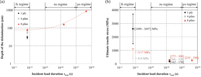
Effects of the load duration and sample thickness: (a) on the location of the delamination, and (b) on the ultimate tensile stress... Barker L M and Hollenbach R E 1972

Type 5: a cyclic tensile test and a stress-relaxation test were successively performed on a porcine skin sample according to the steps: (1) the sample was subjected to cyclic

The human plantaris is hardly functional, but its retention and association with the plantar aponeurosis as in Old World monkeys (53) signals retention of primitive features from

Three intronic nuclear loci (Ncap3, Mamdc2 and Rab21) were sequenced in Gough Island samples (Table S2, Supporting information), enabling comparisons with previously described

Terminologie concernant les personnes ayant vécu ou vivant une expérience concrète de consommation de substances SUJET ÉVITEZ CES TERMES STIGMATISANTS ÉQUIVALENTS TERMINOLOGIQUES

par jour, qui aurait parfois un effet hypotenseur, il faut manger du pain et boire du lait sans sel, choisir de façon judicieuse d’autres aliments et ne faire aucune addition de

Effets civils (art. Mais seule l’incorporation parfaite p rod uit complète assim i­ lation.. L’incorporation parfaite déploie son plein effet : l’incor­ poré est