A//.
335.
UNIVERSITÉ DE MONTRÉAL
Evaluation of the release kïnetics of a press-coated biconvex
core with an impermeable coat
Par
Abrahem Abrahem
Faculté de Pharmacie
Mémoire présenté à la Faculté des Études Supérieures en vue de
l’obtention du grade de Maîtrise es sciences (M.Sc.) en Sciences
Pharmaceutiques
juillet, 2005
C
Université
de Montréal
Direction des bibliothèques
AVIS
L’auteur a autorisé l’Université de Montréal à reproduire et diffuser, en totalité ou en partie, par quelque moyen que ce soit et sur quelque support que ce soit, et exclusivement à des fins non lucratives d’enseignement et de recherche, des copies de ce mémoire ou de cette thèse.
L’auteur et les coauteurs le cas échéant conservent la propriété du droit d’auteur et des droits moraux qui protègent ce document. Ni la thèse ou le mémoire, ni des extraits substantiels de ce document, ne doivent être imprimés ou autrement reproduits sans l’autorisation de l’auteur.
Afin de se conformer à la Loi canadienne sur la protection des renseignements personnels, quelques formulaires secondaires, coordonnées ou signatures intégrées au texte ont pu être enlevés de ce document. Bien que cela ait pu affecter la pagination, il n’y a aucun contenu manquant. NOTICE
The author of this thesis or dissertation has granted a nonexclusive license allowing Université de Montréal to reproduce and publish the document, in part or in whole, and in any format, solely for noncommercial educational and research purposes.
The author and co-authors if applicable retain copyright ownership and moral rights in this document. Neither the whole thesis or dissertation, nor substantial extracts from it, may be printed or otherwise reproduced without the author’s permission.
In compliance with the Canadian Privacy Act some supporting forms, contact information or signatures may have been removed from the document. While this may affect the document page count, it does flot represent any loss of content from the document.
UNIVERSITÉ DE MON TRÉAL
Faculté des Études Supérieures
Ce mémoire est intitulé:
Evaluation of the release kinetics of a press-coated biconvex
core with an impermeable coat
Présenté par:
Abrahem Abrahem
À
été évalué par un jury composé des personnes suivantes:
Professeur Fahima Nekka
Président-rapporteur
Professeur Jean Norbert Mc Mullen
Directeur de recherche
To
my wife, for her support and understanding
To my parents
To my brothers and sïsters
with admiration and appreciation
Acknowledgment
I
would
like
to
express
my
sincere
gratitude
and
appreciation to Professor Jean-Norbert McMuIIen for his support
and valuable guidance du ring the progress of this project.
Acknowledgments
are
also
due
to
Professor
Patrice
Hiidgen for his guidance and assistance.
Special appreciation and thanks to Dr. Miloud Rahmouni
for his help.
Sommaire
Une forme pharmaceutique à libération modifiée basée sur un principe
géométrique a été développée et évaluée pour la libération orale contrôlée et soutenue d’agents bioactifs. Cette forme pharmaceutique est composée d’un noyau biconvexe obtenu par compression directe, enrobé d’une membrane imperméable à l’exception d’une surface de libération radiale. La libération de l’agent bioactif se fait à partir d’une fenêtre radiale de forme cylindrique à un taux relativement constant. Le tartrate de métoprolol et l’aminophylline ont été utilisés comme modèles d’agents bioactifs. Ces agents ont été choisis en raison de leurs propriétés physico-chimiques (solubilité). De nombreuses formulations ont été faîtes pour chaque principe actif avec différents excipients. Afin de développer un enrobage imperméable pour le noyau et améliorer l’adhésion entre le noyau biconvexe et cet enrobage, quelques études ont été effectuées pour évaluer l’efficacité de libération de la drogue, étudier l’effet des excipients dans la formule sur la cinétique de libération, étudier l’effet de la concentration ou du niveau de drogue basé sur le rapport de la partie fortement soluble à la partie moins soluble et étudier l’effet de la surface de libération (non enrobée). Une étude comparative a été faite pour évaluer l’efficacité de libération de drogue en employant un noyau plat et un noyau biconvexe (RRBD). L’effet de la vitesse d’agitation sur le taux de libération a été étudié. L’effet de la force de compression employée pour fabriquer les comprimés sur le taux de libération a été évalué et la valeur de porosité sous différentes forces de compression a été déterminée. Toutes les expériences ont été faites in vitro en utilisant un appareil de dissolution automatisé. Les résultats
obtenus à partir de ce projet de recherche ont démontré l’efficacité du dispositif de RRBD pour contrôler la libération de drogue.
Summary
A drug delivery device based on a geometric design was evaluated for the
controlled and sustained oral delivery of bioactive agents. The device consists of a directly compressed biconvex core, coated with a totally impermeable coat with the exception of the radial releasing window. The drug release from these cores radially, starting from the cylindrical releasing area at the periphery and release the model drug at nearly constant rate. Metoprolol Tartarate and Aminophylline were used as model drugs. These model drugs were selected because of their physico-chemical properties (solubility). Numbers of formulations were made for each pharmaceutical active principle (Metoprolol Tartarate, Aminophylline) with different excipients. In order to develop the coating of Radially Releasing Biconvex Device (RRBD) (i.e. to have a totally impermeable coat) and to improve the interlocking between the biconvex core and the impermeable coat some studies were made. Several studies evaluated the efficiency of these devices; study the effect of the level of excipients in the formulation on drug release, based on the ratio of highly soluble ingredients to low soluble ingredients, study the effect of drug loading , study the effect cf the releasing surface
(uncoated
),
comparative study was made to evaluate the efficiency to control the drug delivery by usîng flat core and biconvex core coated tablet (RRBD), study the effect of agitation speed on the release rate, study the effect of compression force used to press the tablets on the release rate and evaluate the porosity value under different compression forces. AIl the experiments were made in-vitro by using dissolution apparatus. The results obtained from this research project demonstrated the efficiencyTable of content
I. Introduction I
A. Overview of modified Release drug delivery I
1. Generalities 2
2. Considerations 2
3. Definitions 3
4. Advantages and disadvantages of controlled release 4
5. Classification of controlled release dosage forms 5
a) Chemically-controlled systems 6 (1) Bioerodible systems 6 (2) Drug-polymer conjugates 6 b) Diffusion-controlled systems 6 (1) Membrane-reservoir systems 6 (a) Solution-diffusion 6 (b) Osmotic pumping 6 (2) Matrix systems 6
(a) Porous matrix 6
(i) Geometric-controlled 6
(ii) Gradient distribution 6
(b) Polymer erosion 6
B. Oral controlled-release drug delivery systems. 7
1. The design of controlled release systems 7
(1) Continuous-release systems 7
fa) Dissolution control 7
(b) Diffusion control 7
(c) Dissolution and diffusion control 7
f
U) Osmotically controlled devices 7(e) Slow-dissolving salts and complexes 7
(2) Delayed-transit and continuous-release systems 7
(s) Density-based systems 8 (b) Size-based systems 8 (c) Bioadhesive-based systems 8 (3) Delayed-release systems 8 (s) Intestinal release 8 (b) Colonic release 8 2. Dissolution control 8 3. Diffusional systems 11 4. Reservoir devices 11
5. Effect of device geometry on drug release rate 14
C. The influence of geometric design 23
1. Dissolution of solid dosage forms 23
3. Planargeometry .25
4. Multi-layers tablet and cylindrical geometry 28
5. Spherical geometry 31
D. Controlling release rate with geometric matrix systems 32
a) Pie shaped system 32
b) The multi-perforated device 38
c) Cone-shaped and Hemisphere Systems 41
U) Biconcave disc 44
E. Powder characterization 48
1. Density 48
2. Moisture content 49
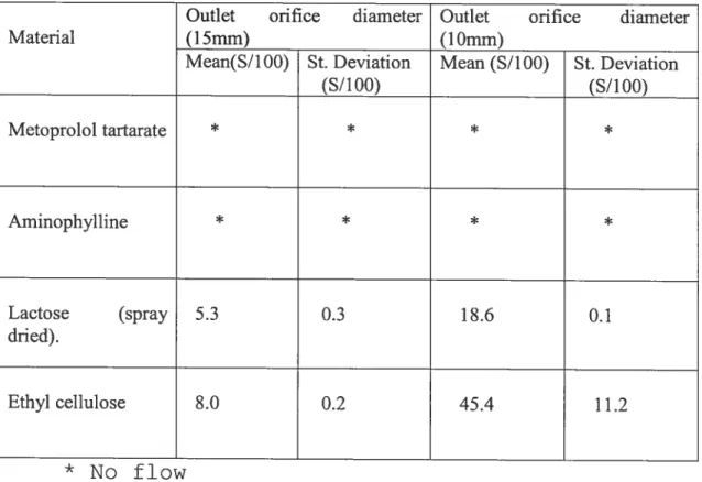
3. Powderflow properties 50
4. Particle size analysis 51
F. The objective of this study 52
II. Materials and methods 53
A. Materials 53
1. Chemicals 53
2. Instruments 53
B. Methods 55
1. Methods of Tablet Manufacture 55
2. Analytical methods 57
b) Powder characterization .58
(1)Density 58
(2) Moisture content 59
(3) Powder flow properties 60
(4) Particle Size Analysis 61
(a) Metoprolol tartarate 61
(b) Aminophylline 63
(c) Lactose (spray dried) 65
(d) Ethyl cellulose (Ethocel) 66
c) Tab let Porosity 66
d) Dissolution and drug releases studies 68
III. Resuits and discussion 68
A. Core Coat Development 68
B. Drug release studies 71
Metoprolol studies 71
a) The effect of magnesium stearate level on Metoprolol release kinetics. 72
b) The effect of dtug foading on release kinetics 74
c) The effect of height at the edge (Releasing window) on the drug release 75 d) The release of MT of formula IV from devices: Flat and Biconvex cores. 77
e) Study the influence of agitation rate on the kinetics profile 79
2. Aminophylline studies 81
e) The effect of compression force on Aminophylline kinetic profile 82 b) The effect of ethyl cellulose on Aminophylline release profile 85 c) The study of Aminophylline from biconvex and flat core devices 87
IV. Conclusion 91
V. Appendix 93
Lïst of Figures
Figure 1: Reservoirdevice 12
Figure 2: Comparison of different geometries (slab, cylinder and sphere
geometries of reservoir systems 15
Figure 3: Release rate against membrane thickness for different geometries of
reservoir devices 17
Figure 4: segment of membrane-coated tablet (A) liquid penetrating into the
membrane, and (B) drug solution diffusing through the membrane 21
Figure 5: Schematic diagram of triple-layer tablets (Geomatrix®) 29
Figure 6: Cross section of zero-order drug delivery system containing solid drug
33
Figure 7: Cross-sectional view of s coated I perlorated device 36
Figure 8: Cross section of a perforated coated tablet 37
Figure 9: Schematic diagram of morantel sustained release trilaminate 39
Figure 10: Schematic diagram of releasing surface area boundaries 40
Figure 11: Cross-sectional view of a cone-shaped device 42
Figure 12: Hemisphere design 43
Figure 13: three dimensional cross-sectional view of the biconcave device (a) Dissolving core, (b) impermeable coating, (c) releasing hole, (U) tablet angle,
Figure 14: Cross sectional view of the proposed device (S. Bechard and
McMullen; solute release from a porous polymeric matrix) 46
Fïgure 15: flat tablet shaped core 55
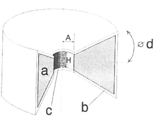
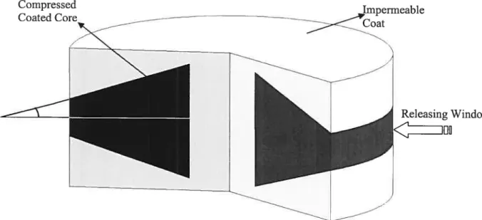
Figure 16: Radially releasing biconvex device (RRBD) 56
Figure 17: Cross sectional view of the proposed device 57
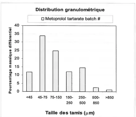
Figure 18: Particle size distribution of Metoprolol Tartarate 62
Figure 19: Microscopic picture of Metoprolol Tartarate particles 63
Figure 20: ParticIe size distribution of Aminophylline 64
Figure 21: Microscopic picture of Aminophylline particles 64
Figure 22: Particle size distribution of Spray Dried Lactose 65
Figure 23: Particle size distribution of Ethyl cellulose 66
Figure 24: Study the release of Aminophylline from device with hole in the coat
vs. press-coated device without central hole 70
Figure 25: The effect of magnesium stearate loading on Metoprolol tartarate
release (Formula I, III, and V) 73
Figure 26: The effect of drug loading of Metoprolol on the kinetic release (formula
I, III, and VII) 75
Figure 27: The effect of height at the edge (releasing window) on the drug
release (formula IV) 76
Figure 28: Study the effect of biconvex vs. flat core device on the release of
Metoprolol tartarate (formula IV) 78
Figure 29: The release rate of Metoprolol from flat core device vs. biconvex core
Figure 30: Study the effect of agitation speed on the kinetic profile of Metoprolol
tarlarate (formula IV) 81
Figure 31: Study the effect of compression force on Aminophylline kinetic profile
(Formula VIII) 83
Figure 32: The effect of compression force on the pore size distribution 85 Figure 33: The effect of ethyl cellulose level on Aminophylline release (formula
VIII, IX, X, and Xl) 87
Figure 34: Study of Aminophylline release from biconvex vs. flat core device .... 89
Figure 35: The rate of Aminophylline released from flat core vs. biconvex core
List of Tables
Table 1: Evaluation of the permeability of compressed insoluble polymers 5$
Table 2: Study the density, compressibility index and moisture content 59
Table 3: Study the flow property of the used ingredients 60
Table 4: Core composition, Metoprolol,(%w/w) 72
Table 5: Core composition, Aminophylline, (%wlw) $2
Table 6: Pore size distribution of different disks compressed under different
I. Introduction
A. Overview of modified release drug delivery
During the last decades, research in modified drug delivery has led to increasingly sophisticated sustain drug deiivery systems. It has also stimulated greater awareness among the pharmaceutical industry, the regulatory agencies, the health care profession, and the public at large for the therapeutic advantages of modified drug delivery systems. Presently, the majority of these systems are based on the use of synthetic polymers that differ in their degree of erodibility, swellability, and sensitivity to the biological environ ment in which they are placed. These polymers have been used to design systems such as microcapsuies and nanoparticles for implantation, hydrogels for oral and patenterai drug delivery, the osmotic pump for oral drug delivery, and patches for transdermai drug delivery. (1)
Drug concentration, aqueous solubility, moleculat size, crystal form, protein binding, and pK are among the physicochemicai factors that must be understood in order to design a delivery system that exhibits controlled or sustained release characteristics. Controlled and sustained release preparations using alternative routes have been formulated but the oral route still remains the most widely studied and used. It is obvious that, very highly water soluble drugs (hydrophilic) are more difficult to deliver orally in sustained or controlled release manner than hydrophobic drugs. (2, 3)
J.
Generalities
The pharmaceutical dosage form can be defined as a pharmaceutical system delivering a drug to an organism. There are two different parameters relating to drug delivery: the amount of drug released over a unit of time and the drug elimination process, including drug metabohsm (biotransformation) and excretion. The rates of these two concurrent processes, physicochemicat and physiological, determine the ength of time that an effective drug Ieve in the circu’ation to obtain a specific
pharmacological action is maintained. This Iength of time is determined by the so-called biological haif-life, on which basis duration of drug action can be established.
A drug characterized by short biological haif-life must be administered
at short intervals to maintain the pharmacological action, which makes patient compliance difficuit to obtain. The ideal dosage form would be a once-daily dosage form, i.e., one which when administered once daily woud remain the therapeutic drug level in the body for 24 h without the risk of toxic concentration. (4)
2.
Considerations
Both of the absorption and elimination processes should be taken in consideration when considering the theoretical possibilities of prolonging the time of drug retention in an organism. Therefore the fotiowing
Prolongation of absorption > Prolongation of metabolism > Prolongation 0f excretion
3. Definitions
Over the years, there has been available a variety of pharmaceutical dosage forms which have affempted to control the time course and specificity of drugs in the body; these have been identified by various names, such as “controlled release,” “sustained release,” “prolonged release,” and “timed release.”
The term “Controlled release dosage forms” (CRDF) implies that the drug release kinetïcs, prolonged, sustained, or timed, is predictable and reproducible from batch to batch and from patient to patient. CRDF is not influenced by the external environment in which the drug is released, but by the device itself. The release of active agent is, therefore, largely independent of external factors.
Sustained release means that the release of the active agent is
constant over time. (5, 6)
Long-acting or prolonged-action system: in which a dosage form
containing a therapeutic substance modified chemically in order to prolong biological half-life. (4)
4.
Advantages and disadvantages of controlled release
Controlled release delivery systems offer many advantages over conventional or traditional formulations that deliver the entire active ingredient over a short period of time. We can summarize them as the following:
One of the most important advantages that can be achieved by using sustained release devices is constant blood levels of active ingredient release requiring considerably less ingredient to produce a given duration of action in comparison to conventional system.
A second advantage of sustained release system is maintaining the
concentration of a drug between the minimum effective and toxic levels, (above the minimal therapeutic level), eliminating the peaks and valleys of the conventional systems.
Controtled release systems usually offer a mean of circumventing the
problems of overdosing and underdosing inherent to conventional
formulations. Controlled release system can be designed in which the rate of drug release equals to the elimination rate, in order to achieve zero or near-zero order drug kinetic (steady state). (7)
Controlled release technique makes it possible to deliver the agent locally by its containment at the site of action. Local delivery and containment reduces the dosage required and the possibility of side effects.
A good example for local drug delivery system is intrauterine contraceptive
contraceptive. Theses steroids produce a contraceptive effect at release rates as low as 10 to lOOpg/day, while the same steroids given systemically would require more than 1,000 times the local dose to be effective. Because of the low dose required, a controlled release device can contain sufficient drug to produce a contraceptive action for a year or more. (7)
To reduce the frequency of dosage during the day, this simplifies the dosage regimen and reduces the risk of missed doses administered either by patient or by the hospital staff (to improve patient-comfort), thereby insuring patient compliance (7)
5.
Classification of controlled release dosage forms:
Controlled release dosage forms (CRDF) are designed to maintain
drug plasma concentrations within a therapeutic range. However,
pharmacokinetic response from each CRDF varies from product to product. The pharmacokinetics information on the drug is an essential element to determine the feasibility of a controlled-release dosage form for that drug. Obviously, drugs with relatively short half-lives (less than 6 hours) and specifically defined minimum therapeutic blood levels would be the most likely candidates for controlled delivery. Drugs with half-lives in the blood exceeding 6 h could be dosed in conventional dosage forms such that therapeutic blood levels would be established and then be self-sustaining, allowing for twice daily dosing or less. One limitation to this approach would be encountered with a drug with a narrow safety margin. Furihermore, well
defined minimum therapeutic blood levels of a dtug generally are difficuit to establish. (9)
A useful classification of controlled release dosage forms according to
the mechanism controlling the drug release as follows: a) Chemically-controlled systems (1) Bioerodible systems (2) Drug-polymer conjugates b) Diffusion-controlied systems (1) Membrane-reservoir systems ta) Solution-diffusion (b) Osmotic pumping (2) Matrix systems
fa) Porous matrix
(i) Geometric-controlled (ii) Gradient distribution
(b) Polymer erosion (c) Polymer swelling
B. Oral con trolled-release drug delïvery systems
1.
The design of controlled release systems
Most of the oral controlled release systems rely on dissolution, diffusion, or a combination of bath mechanisms, ta create slow release of drug to the gastrointestinal milieu. In order to achieve a systematic approach to the design of an oral controlled release product, it is necessary to understand the following:
a) Physicochemical characteristics of the drug
b) Dosage form characteristics and formulation techniques. c) Gastro-intestinal physiology and pharmacokinetics
A review of the literature has revealed the recent development of
several novel drug delivery systems that can be utilized for the controiled delivery of drugs in the Cl tract. (1, 10, 11).The following classification of such systems is chosen because it includes both the conceptual approach of the design and some elements of physiology of the Cl system.
(I) Continuous-release systems fa) Dissolution contrai
(b) Diffusion control
(c) Dissolution and diffusion control (d) Osmoticaily controlled devices (e) Slow-dissolving saits and complexes
ta) Density-based systems (b) Size-based systems
(c) Bioadhesive-based systems (3) Delayed-release systems
(a) Intestinal release (b) Colonic release
2. Dissolution control
When a tablet or other solid dosage form is introduced into a beaker of
water or into the gastrointestinal tract, the drug begins to pass into solution from the intact solid form. Unless the tablet is a contiguous polymeric device, the solid matrix also disintegrates into fine particles and/or granules. Disintegration, deaggregation, and dissolution may occur simultaneously with the release and dissolution of drug from its delivery form.
Drug release over a prolonged period can be achieved by employing dissolution as the rate-limiting step in drug release. The delivery of some drugs is inherently sustained because of their intrinsic low aqueous solubility which. Examples of drugs in this category include Griseofulvin, Salicylamide, and Digoxin.
While for highly soluble drugs, the solubility rate can be controlled by one or both of the following:
a) Coating of a drug particles or granules with materials of varying thickness having low solubility
b) Dispersing the drug particles into an insoluble polymeric matrix
The main principle of dissolution control is as follows: (12) when the dissolution process is diffusion layer controlled, where diffusion from the solid surface through the aqueous diffusion layer (stagnant liquid film) to the bulk solution is rate limiting, the flux J is given by:
J=—D(dc/dx)
(Equation 1)Where,
D = the diffusion coefficient
dc/dx = concentration gradient from solid surface to the bulk solution
The flux can also be defined as the flow rate of material (dm/dt) through a unit area (A):
dm/dt
(Equation 2)
If the diffusion layer thickness is h and the concentration gradient is linear,
(dc/dx)
=(,
—C
)/
h
S
(Equation 3) Where,
C = concentration at the solid surface (saturation)
By combining the above equations, the flow rate of material is given by:
(dm/ dt)
=(DA/h )kC
—Cb
)
=kA
(Ç
—Cb)
Eq. 4 Where,K = the intrinsic dissolution rate constant.
Equation 4 predicts constant dissolution rate if the thickness of diffusion layer, diffusion coefficient, concentration difference, and surface area maintained constant. However, as dissolution proceeds, the surface area decreases.
A practical expression that describes the dissolution of dosage forms
of various geometries is available (13) Thus,
M /M
=1
—[(1
—k
t)/c a]”
t ° ° (Equation 5)
Where,
= the amount of drug released in time t
Mc= the amount of drug released at infinite time a = the thickness
3.
Diffusional systems
In diffusional systems drugs can diffuse through polymeric matrix while either leaving the latter intact or the polymers themselves may undergo subsequent biodegradations following exhaustion of the drug. Biodegradable systems do flot need to be surgically removed after therapy. The simplest example of a diffusional system is one in which a drug is included in a reservoir (core) from which it can diffuse out through a membrane. The kinetic behavior of a drug can follow zero-order as long as the drug concentration in the core is maintained in highly saturated state.
4.
Reservoir devices
Reservoir systems are commonly used in the field of controlled release, as diffusion-controlled systems. To achieve optimum therapeutic effects particularly for drugs with short biological half-lives, it is often desirable to have a zero-order drug release. The kinetics of drug release from such a membrane-reservoir system generally follows either a solution-diffusion or an osmotic pumping mechanism. In a membrane reservoir system, a water-insoluble polymeric material encases a core of drug. Drug will diffuse through the membrane and exchange with the media surrounding the tablet or particle. Additional drug wilI enter the membrane, diffuse to the periphery, and exchange with the surrounding media. b keep the drug release constant, the reservoir must be
saturated. The movement of drug or solvent is governed by membrane. The membrane permeability to the solvent and the drug determines the diffusion rate of molecules through the membrane. The most important advantage of using reservoir systems is the possibllity of achieving a constant rate of release over a substantial portion of their lifeUme. A second advantage is that the level of drug loading can be higher compared to other systems.
Figure 1: Reservoir device
The diffusion rate across the membrane is given by Fick’s law:
J
=—Ddc/dx
(Equation 6)Ac e ni
Where,
D = diffusion coefficient in area / time
dcldx= the change of concentration C with distance x
At steady state, equation (6) is integrated to give by
J—DAC/1?
(Equation 7)In terms of the amount cf drug released, the release rate dM/dt is
given by
dM
/
dtzzADKAC
/ £
(Equation 8)Thus,
A = the area
D = the diffusion coeffïcient
K= partition coefficient cf drug between the membrane and drug core
f = the diffusional path length (thickness of coat in the ideal case)
1X0 = the concentration gradient across the membrane
A significant factor in Equation (8) the partition coefficient which is
concentration of drug in the core. If the partition coefficient is high, the core wîII be depleted of drug in a short time so that zero order release will be observed only over a short segment of the time course of drug release.
In fact, to get a constant drug release rate from a reservoir device it is
crucial to keep constant area, diffusional path length, concentration, and diffusion coefficient. (1,6,7, 15)
5.
Effect of device geometry on drug release rate
As discussed previously the diffusional controlled matrix systems have some advantages over other systems particularly when compared to the fabrication of reservoir systems. A main disadvantage is that they do flot inherently possess zero-order release kinetics. However, these systems can avoid the diminishing release rate as the drug diffuses from longer diffusion Iength or lower drug concentration distribution. This difficulty is particularly severe for spherical and cylindrical shaped devices. An achievable sotution to get zero-order release behavior is to modify the matrix geometry. Examples of different geometries, e.g. pie, hemisphere, or cone are illustrated later.
_ 2r, . t tc) Sphere 2r0 2r
Fïgure 2: Comparison of different geometries (slab, cylinder and sphere geometries of reservoir systems
The rate of release of an active material from a reservoir device can be controlled through geometric factors. Equation 6 can be modified for the slab or sandwich geometry as show in Figure 2
dM /dt=AJ. /Ï=ADKC Il
t lilTiS
Where,
(Equation 9)
M is the released drug mass at time t and since dM/dt is the steady
state release rate at time t. A is the total surface area (edge effects being
ignored), and Jiim is the membrane-limiting flux. (7)
For the cylinder, the steady-state release rate (ignoring end effects) is given by fa) SIab (b) Cy1nder eaero
cliv!
/
dt
=27rhJ1.
/
1nr0
/i =2,rhDKC
/
ln(r0 /
r) (Equation 10)Where
r0 and r1 are the outside and inside radii of the cylinder, respecfively,
and h is the iength of the cylinder. For the sphere,
r r.
4îcDKC r r.
dM/dt=4irJ.
0
i=SO±
(Equafionil)llffir —r r —r
Oi
Oi
The sphere is a particularly interesting geometry since in the limit as
r0/r—
cq
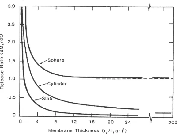
dMt/dt—>47cDKC1That is, the release rate becomes independent of the outer radius of the device, r0. A plot of flux against the ratio r0/r1, as illustrated in Figure 3, when r0/r exceeds approximately 4, further increases in device size for a fixed radius core does not significantly affect on the release rate. Since almost ail the concentration decrease is within a distance of a few radii of the inner core. Thus, a given size reservoir provides a constant release rate for any thickness of membrane beyond a certain limit, making membrane thickness a noncritical parameter in device fabrication.
30
2.0
Figure 3: Release rate against membrane thickness for different geometries of reservoir devices
Increasing membrane thickness with the various other geometries affects release rate quite differently. As shown in Figure 3, in which the release rate is plofted as a function of membrane thickness for devices of various configurations. In figure 3 it is obvious that none of these geometries give zero-order release for the following reasons. For the slab geometric device, the area remains constant, yet the distance of the receding boundary from the releasing surface increases with Urne. Therefore, the increase in diffusional path length results in a release rate
25 1.5 1-o 0.5 o 8 12 1 20 Aembtan Thcknes or Ç) 200
that decreases with time. The release rate is inversely proportional to thickness, and release rates are thus easily scaled over a wide range. For the cyflnder and the sphere, the decrease in the release rate ïs more pronounced, since the area decreases with time, whereas the distance of receding boundary increases with time.
a) Matrïx device systems
Diffusional matrix systems are the earliest most utilized means of bioactive agents delivery. In this system the drug particles are dispersed uniformly in an insoluble polymer. The drug releasing rate is governed by the penetration rate of surrounded medium into the matrix from the surface. This, in turn, is controlled by the porosity of the tablet matrix, the presence of hydrophobic additives, and the wettability of the tablet and particle surface.
When s diffusional rnatrix system cornes in contact with an external medium, as the drug dissolves, the diffusional path length increases because as the dissolution front recedes from the surface.
The main disadvantage of matrix devices is that drug release rate continuously decreases with time. This is an end result of increased diffusional distance and decreased surface area at the penetrating solvent front; therefore it is not possible to obtain zero-order kinetic by using this kind of device. The geometry can be modified to compensate for the
surface area for dissolution, thereby increasing the amount cf solubilized particles per unit of time resulting in near zero order release from matrix device. (16, 17)
In this matrix system the releasing rate of a drug is based on the
diffusion rate of a drug. Higuchi’s equation can be used to express the amount cf drug released from this device:
Q
=[Ds/T(2A—&c 7
(Equation12)Where
Q = drug released in g per unit surface area
D = diffusion coefficient of drug
E = porosity of the matrix n = turtousity of the matrix
C = solubility of drug in release medium g/ml
A = concentration cf drug in the tablet
‘- The particles size of the drug is much smaller than particles in the
matrix
> No interaction between the drug particles and the matrix
> Constant diffusion coefficient
A pseudo- steady state is maintained during release C = O in the bulk solution at ail times
A » Cs
f
saturated conditions)This equation can be reduced to
1/2
QzKt
(Equation 13)A plot of drug reieased (mg) versus the square root of time should be
linear if the rate drug release is diffusion controiied. The rate of drug release from a homogenous matrix can be controlled by changing one of the following parameters
:(
18)• The soiubility of drug
• initial concentration of drug in the matrix • Porosity of the matrix
• Tortuosity
• Leaching solvent composition • Polymer system making up matrix
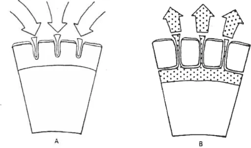
Membrane-coated tablets were developed to provide a dosage form which exhibits zero-order kinetics. The delivery system consisted cf a soluble tablet core surrounded by a porous membrane which controls the diffusion rate. The water from the gastric juices diffuses through the pores to reach the core to dissolve the drug which then diffuse back through the water filled pores and eventual release into the gastric juices. Such a device using membrane coating as a diffusional barrier is represented in Figure 4 Membrane-Coated Tablets (19):
Figure 4: segment of membrane-coated tablet (A) lïquid penetrating into the membrane, and (B) drug solution diffusing through the membrane.
The rate of release cf drug from the tablet through the pores can be calculated by using Fick’s first law cf diffusion.
Q
=DC5,
—C
J
A/h
(Equation 14)Where
Q = rate 0f release
D = diffusion constant
A = surface area
h = thickness of the diffusion layer (i.e. film)
As long as there is a saturated solution together with solid drug substance inside the coating shell, the concentration inside the coating sheli, C, is much higher than the concentration outside the coating shell, C. which means C is negligible compared to C and equation (14) can be reduced to:
QDC /hA
(Equation 15)This implies that the diffusion should proceed at a constant rate (zero order reaction). At the point where no solid substance is left within the membrane coating, the rate of diffusion declines with decreasing concentration (first-order reaction).
C.
The influence of geometric design
1.
Dissolution of solid dosage forms
Once a solid dosage form is placed in a Iiquid medium dissolution begins. The dissolution rate cf a solid dosage form decreases with time because of the decrease in dissolution front surface area. Furthermore, the diffusional path length increases making it difficult to keep the release rate of drug in constant level and then no zero-order kinetic. From that point the geometric design promises to overcome the decrease in dissolution front surface area.
The familiar cube-root law for dissolution of solids was derived by Hixon and Croweil on the basis of diffusion away from the surface of a spherically-shaped solid. The convex surface of a sphere decreases in area as solid mass is lost from the surface so that the dissolution rate decreases
in portion to the decrease in area until the solid is completely dissolved. By
including shape factors, this model has been extended to describe the dissolution of varlous prismatic forms (20). As in the case of spherical particles, the dissolution rate decreases with time as the dissolution process progresses because of the decrease in area.
The surface area in the case of a concave device increases as solid mass is eroded from the surface. Therefore the rate cf dissolution increases with time. Rippie and Johnson (21) studied the dissolution characteristics of solid pellets that were designed to minimize loss in surface area during dissolution. This was accomplished by employing pellets having a cross
section such that both convex and concave surfaces were present. Dissolution rates of pellet cylinders having a cross shape and clover leaf cross sections were measured and compared with that of a right cîrcular cylinder. Although the dissolution rates of the uniquely-shaped pellets decreased over time, with partially coated pellets the rates decreased much less than that of the circular cylinder, e.g., after 60% mass loss the rates were approximately 55% greater than that of the circular cylinder.
When a hole is present in a nondisintegrating tablet, the convex surface of the hole will increase in area as the surface dissolves. A theoretical analysis by Cleave (22) on tablets in the form of parallelepipeds indicated that the presence of one or more holes in a tablet can alter significantly the dissolution rate of the tablet over time. It was concluded that a two-hole tablet is basically a better configuration than the others for maintaining a constant dissolution rate. (14)
2.
Geometrically Modified Systems
The diffusion-controlled monolithic matrix systems have some
advantages over other systems especially when compared to the
fabrication of reservoir systems. A major disadvantage is that they do not inherently follow zero-order release kinetics. However, these systems can overcome the decreasing release rate as the drug diffuses from longer diffusion length or lower drug concentration distribution. This difficulty is
factors have been utilized to compensate for the increasing diffusional distance and decreasing area at the dissolution front generally encountered
in matrix systems. Many geometrïc designs have been proposed in the
literature which modifies the planar geometry of a matrix device from which the fraction of drug released was linear with the square root of time (23, 24).
3. Planar geometry
The release kinetic of a drug from planar geometry composed of a homogenous matrix, where the amount of drug released from planar device into the surrounded media acting basically as a perfect sink can be described by the following retationship;
QDt[2A_C C
(Equation 16)Where,
Q = drug released after time t
D = drug diffusitivity
A = the total amount of drug present in the matrix per unit volume
For the release from a planar system having a granular matrix
composed of dispersed drug particles in an inert polymer. The above
relation must be modified to account for the effective volume where diffusion can occur and the effective diffusionat path. It can readily be seen for this system that
QD&/T[2A—c Ct
(Equation 17)Where,
Q = the amount of drug released after time t per unit exposed area
D = the diffusivity of the drug in the permeating fluid
r= the tortuosity factor of the capillary system 3
A = the total amount of drug present in the matrix per unit volume C= the solubility of the drug in the permeating fluid
E = the porosity cf the matrix
The origin ofthe above expression is basically the same as for Eq.16,
except that the effective diffusional cross sectional area must be reduced by the porosity factor E, and the solubility of the drug in the total system per
unit volume must also be decreased by the same factor.
The tortuosity factor, T, is introduced to correct, for the tengthened
For both equations (25) it is assumed that there exists a pseudo steady state condition during the release process and that the drug pattîcles are quite small and is uniformly distributed in the matrix. The equations would be fundamentally valid for systems in which A is greater than C or
EC by a factor of three or fout. 0f course, if A < C or ECs, the dtug would
flot longer be ptesent as a solid and a different equation would be apply. Since the potosity factor in Equationl7 refers to the porosity of the leached portion of the pellet, it diffets from the initial porosity of the initially formed matrix. The difference would correspond dîrectly to the volume of space previously occupied by the exttacted component or components.
Thus
+KA
(Equation18)For systems where the drug is the only extractable component, K being introduced to convert A to its corresponding volume fraction. K is equal to the specific volume of drug = II (density of the drug) if A is expressed in terms of grams of drug per milliliter. For those instances where the initial porosity, E0, is very small or where the fraction of the matrix volume occupied by the drug is relatively large E KA and equation 17
QAJDK/T[2KC Ct
(Equation 19)Therefore in this system the amount of drug released at anytime is basically independent of A.
4.
Multi-layers tablet and cylindrical geometry
To design controlled release dosage forms for oral use there are various ways: from tablets or capsules, film coated pellets, to more complicated drug delivery systems. Hydrophilic matrix systems are considered to be the easiest way to formulate a drug into a prolonged release dosage form. Generally the mechanism of drug release from hydrophilic, swellable matrices couples polymer macromolecular relaxation with drug diffusion with the resulting kinetics depending on the relative ratio of relaxation to diffusion. (26, 27)
Cone et al. (28) developed a multî-layer tablet system (Geomatrix®) as shown in figure 5
Figure 5: Schematic diagram of triple-layer tablets (Geomatrix©)
A core tablet is sandwiched between two barrier layers. By using
hydrophilic swellable/erodible polymer zero-order kinetics can be achieved. However, zero-order release kinetics also depends on the solubility of drugs. 1f the two layers were hydrophilic swellable polymec, the drug release rate is controlled by several mechanisms. When the device is placed in water, hydration of the polymer will start and then the drug diffuses toward the surrounded media. When liquid penetrates through the barrier layer, the drug will dissolve and then diffuses out. Then the swollen barrier can be considered as a membrane. lnitially, the drug kinetic release is governed by the diffusion of drug through the swollen barriers because the total lateral surface area is greater than the radial surface area. Core tablet hydration is delayed due to the drug-fcee barrier layers. In addition, the thickness of the swollen barrier layers diminishes with time, leading to a decrease in the diffusion resistance of the membrane. This counterbalances the effect of the reduced concentration of the drug in the core tablet on the drug release
kinetics, leading to the prolonged zero-order release. Sînce, the release of a drug from this system is essentiaily based on the solubility of a drug, when the solubility of a drug is low, then the release kinetic can be much close to zero-o rder.
Formulating tablets containing different dose levels with identical release kinetics is considered to be the greater source of trouble during the development of controlled release dosage forms based on tablet geometry
The tablet design necessitates altering the formulation and tablet size. Therefore, each tablet requires a unique formulation for each dose level. Cone et al. (29) developed small tablets with multi-layer system design which can be placed in a hard gelatin capsule. In this system, the release kinetics of different dose levels shows the same release profile.
This multi-layered tablet system has been reserved to press-coated tablet system. The press coated tablet system consists of an outer low drug (or drug-free) content layer and a high drug content core (30). This device was prepared as follows: A specific amount of blend of coat excipients is put into a die (bottom layer) then compressed with a flat-faced punch followed by placing the core tablet in the middle of the bottom layer. The rest of the mixture is then poured into the die forming the side and top layer.
In press-coated system the drug release delay by the coating barrier varies
according to the coat thickness and the type of materials. The barrier is able to slow down the hydration/swelling process of the core tablet for a long period of time. Further more, the outer barrier layer works as a controlting
membrane producing a linear release profile as long as the drug concentration in the cote is at saturation level.
5.
Spherical geometry
By applying the Fick’s first Iaw in this system
Qt=—4zcr2DdC/dr
(Equation 20)Where,
Qt = the diffusion rate
D = the diffusion coefficient of drug molecu les in the matrix
o
=the concentration of the drug in the polymerAs in the cylindrical geometry approach and under the same boundary conditions and presuming that the diffusion rate of solute from the matrix is constant (pseudo-steady state), the next equation can be derived:
Qt
=4D
(CM —CbK)
(Equation 21)[ï / RQ)}—[1/R0]
Similar to the cylindrical geometry, as equation 21 shows, the concentration profiles for the pseudo-steady assumption are no longer linear with respect to the radius. The following equation is achieved, which illustrate the correlation between R (t) and t.
CT
R2
(Equation 22)
D(CM
It is obviously that ail of the three different geometries do not follow zero-order kinetic release behavior for different reasons. In both cases of sphere and cylinder the decline in the release rate is more marked, resulting from the decreasing in the area with time, and the increasing diffusional distance because of the receding boundary. In the case of slab geometry the main cause is that while the surface area stays constant, the diffusional distance increases with time.
D. Controlling release rate with geometric matrix systems
a) Pie shaped system
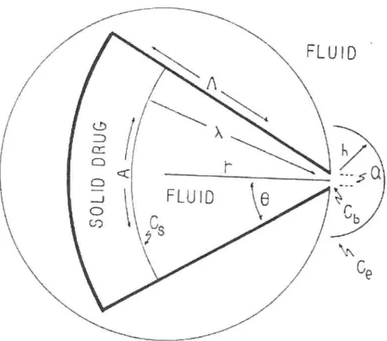
Brook and Washkuhn (31) have presented the pie shaped device to
deliver a drug in order to reach zero-order kinetic. The release of a dtug from a polymer matrix could be governed by dissolution or diffusion. The principle of this design is based on compensating for the increase in diffusional path length by increasing the dissolution front area thereby increasing the amount dissolved within the device. The device composed of a nonpermeabie section of a cylinder with a cavity having a circular sector cross section as shown in figure 6. The cavity communicates (releasing window) with the medium (fluid) in which the device is placed
n
only through a narrow opening of width a. The release from this device was tested by following the release of stearic acid into ethanol. The device has demonstrated a good linearity following an initially higher rate, “burst” The ideal behavior of this device depends in theory, however, on both the drug molecules and the releasing window through which they must pass having infinitely small dimensions.
Figure 6: Cross section of zero-order drug delivery system containing solid drug
Lipper and Higuchi (32) took the size of the opening into their considerations to present a theoretical expression for drug release from pie-shaped devices. The flux J, for diffusion path length s, is given by:
J
=2OirLD(s+n
‘c
(Equation 23)ds
Thus,
J = the flux at r
O = the half-angle of the pie
D = the diffusion coefficient of the drug in the dissolution medium
S = the diffusion path length
n =the opening radius
C =the drug concentration
At pseudo-steady state (constant flux), integration of equation (23) with
respect to both distance and concentration yields:
2OLD(C -C)
J= S (Equation 24)
‘n—
I’Z
Where
Cb the drug concentration at the opening
À =the distance between the centre cf pie device and the moving front
However, diffusion from the opening cf the device into the surrounded medium is expressed for sink conditions by:
J2OLDnCb /h
(Equation 25)Where
h = the stagnant film thickness
By solving equations (24) and (25) for Cb, and taking into account
the mass dissolved at time t, M = (Â2 — n2) LOp, the following relationship between the mass dissolved and time can be obtained:
[M+1/Lepn2l T=[h/n—1/2)1v! +LOp 2/2] In
2OLDC ffquafion 26)
However, if one considers the mass dissolved in the diffusion layer between  and O, the following equation may be derived for relating À and
lir —n2 LOp —LOC8 + LOCH — LOC 1n (Equation 27) 2—+1n —+ln— n n n n
Hanssen et al (33) and Conte et al. (34) developed the perforated, coated tablet (PTC) and Boeffner et al. (35) presented the multi-perforated trilaminate. A single perforated tablet, (as show in figure 7), is made by direct compression of drug and other excipients (magnesium stearate and lactose). Then the device was coated by spraying a polymer solution and after that a central hole has drilled.
Figure 7: Cross-sectional view of a coated I perforated device
In this device the relationship between the drug release kinetics and
release of the drug from this device is linear. However, Hanssen et aI. (36)
when a water insoluble polymer ïs integrated into the matrix a
considerable decrease in the rate of dissolution followed with obvious deviation from zero-order manner was observed.
Conte et aI (34) made-up perforated coated tablet with a central hole by spraying a coating solution. This device is consisting of hydrophobic polymer; the central hole represents the window through which the drug is released to the surrounded medium, as long as the diffusional length increases the surface area at the dissolution front increases, giving a good linearity. During the coating operation, however, the inner surface of the central hole may be coated to form a film
ng
Figure 8: Cross section of a perforated coated tablet
Dru
Equation (27) can be modified ta calculate the amount of drug released from perforated-coated tablets by replacing 8 with n as:
M
r
‘22’[L7rp-L7rC+L7rCJ
2(Ji/n+1n/n)
]
h/n+lnÂ/n
b) The multi-perforated device
(Equation28)
It is composed of two layers coating the top and bottom side of core matrix. In this device the coating layers are totally impermeable ta the drug. Circular perforations are punched from the top ta the bottom. On the other hand, the drug can only release through the perforated hales and uncoated sides. The amount cf drug released from this device basically depends on the number of perforations and size of the device as weII. (37). Model equations have been developed to predict the release of drug from the mufti-perforations as follows for a coated edge:
Mr = —n2)LICE p—C5 + —n2)pv +2rp1n 2 n 2DC5 Equation 29 Equation 30 ivr n — 1z6 nr n
And for an un-coated edge, M,. = N(2 — )Ls[P — + 2+1n][±
]+
s[
—EC)Ct]’ Equafion 31 Whereand t are the porosity and tortuosity of the matrix, respectively, N îs
the number of holes, and S is the surface perimeter of the edges.
uncoatcd edges coated edges
Figure 9: Schematic diagram of morantel sustained release trilaminate
Kim (38) proposed a simple un-coated-compressed (swellable
/erodible) tablet with a central hole (donut-shaped). In this device the kinetic release is zero-order (i.e., 80 — 90% of theophylline was released)
before rapidly decreasing. The release of drug in this system depends on the size of hole when the hole size is increased from 5/32” to 7/16”, the
J
o
o
o
o
o
o
o
o
o
-, //
z
/ 7release rate încreases and it is obviously that the time needed for release
ïs shortened.
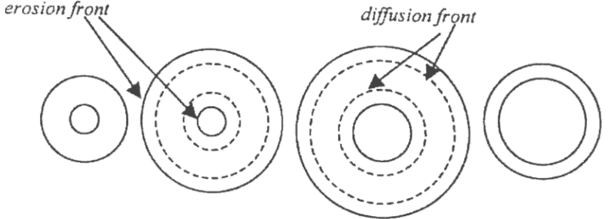
The combined process of boundary erosion and diffusion front progression during drug release from the donut-shaped tablets, Figure 10), compensate for the decrease of releasing surface area from the outer surface by the increase of releasing surface area from the central hole. At the end of drug release, the swollen gel thickness of the donut-shaped tablet is thin enough to be broken by fast stirring. (39)
Figure 10: Schematic diagram of releasing surface area boundaries
However, if the hole size is smaller than 5/32”, the hole collapses during drug release due to the inner swelling of the polymer from the central hole. As a result, the drug release from a small hole donut-shaped tablet tends to follow the drug release from the tablet without a hole.
Kim (40) has developed coated donut-shaped tablets, an improvement of perforated-coated and donut-shaped tablet. Water-soluble polymers and swellable/erodible polymers have been used in perforated coated tablets. In this system, drug diffusion and/or polymer erosion govern drug release kinetics, providîng parabolic or linear release profiles.
c) Cone-shaped and Hemisphere Systems
Nelson et al introduced the cone-shaped device, Figure 11, this system is essentiatly based on the theory that the surface area at the diffusional front increases as the diffusional path increases. The device consists of a non-permeable coat at the two sides (top and boffom), and then the drug can be in between or dispersed in the matrix. The drug can be released through the small hole at the bottom of the cone. Once the
Iiquid starts to penetrate through the hole, a drug-depleted layer forms
Figure 1f: Cross-sectional view of a cone-shaped device
Nelson et aI. (41) treated the release of drug from the device as a pseudo-steady state diffusion in a hallow sphere with a declination angle
8.
Hsieh et al. (42) studied the release kinetics from a hemispheric matrix as presented in Figure 12 in which the device is coated on ail surfaces with an impermeable coating except for an orifice in the centre face. Hemispheric systems for Iow molecular weights drugs were prepared by heating and compressing poly-ethylene and drug (sodium salicylate) in a brass mold. Hemispheric systems for high molecular drugs were prepared by casting ethylene-vinyl acetate copolymer and protein in a hemispheric mold at— 80° C, followed by a two-step drying procedure (-20
coared
Experimental analysis of the device demonstrated that a
hemispherical, receding layer is produced, with the radius of that layer
increasing as a function cf time. Theoretical analysis was also
accomplished to develop release equations for the hemispheric device. In the theoretical analysis, it was supposed that the amount of drug present per unit volume, C0, is substantially greater than the solubility of drug per unît volume of the vehicle, Os. It is also assumed (43), which the solid drug dissolves from the surface layer of the device first. When the layer is depleted of drug, the next layer begins to be depleted. The interface between the region containing dissolved drug and dispersed drug moves into the interior as a front. According to these assumptions, and several others, the release rate equation was derived as follows:
dQ
=
2C DA
t) (32Equation 32)dt
S tWhere
C = solute solubility in the polymer
D = diffusion coefficient
R(t) = radius of the receding boundary
A1 = radius of the spherical cavity
When R(t)» a, equation (32) is reduced to
d%/2ICCDA
(33Equation 33)
Equation 33 shows that the release rate is independent of time, t, and therefore a zero-order release kinetics is atlained.
U) Biconcave disc
Benkorah and McMullen (57) have presented a biconcave disc. It is composed of a slow-dissolving biconcave core of a drug /excipient mixture coated with a totally impermeable membrane. After coating an opening is made through the center of the disk to expose a cylindrical releasing sur[ace which represents the only way by which the device can contact
the surrounded medium. In this device the release kinetics depends on the increase in surface area at the dissolution front to counterbalance the Iengthening of the diffusion path.
d.
Figure 13: three dimensional cross-sectional view of the biconcave device fa) Dissolving cote, (b) impermeable coating, (c) teleasing hole,
f
d) tablet angle, (A) hole radius, (H) hole height.Studies cf the effect of the geometry of the proposed device suggested that release rates, can be predetermined by controlling the diameter of the hole provided that suitable formulations are selected. The study also proposed that constant release rates are better achieved with smaller holes. A high altering from zero-order is obvious as a result cf
J,
large hole size large, mostly when formulations of highly soluble drugs, with high intrinsic dissolution rates, were used.
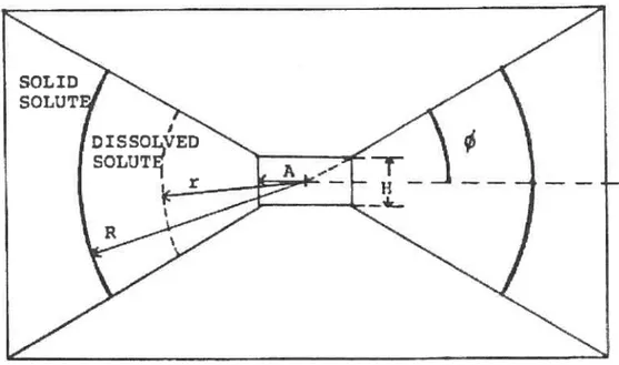
Another approach, developed by Bechard and McMulIen (45)
illustrates kinetics profile 0f a drug from a polymer matrix device. This device is composing of polymer matrix with a central hole, inwardly tapered disk which was planned to be implanted in order to release bioactive materials at a constant rate over an extended period of time.
Figure 14: Cross sectional vïew ofthe proposed device (S. Bechard and McMullen; solute release from a porous polymeric matrix)
The principle of this approach based on the increases in drug diffusion path followed by the increase in area of the dissolution boundary.
In this approach a biconcave polyethylene disc matrices with a releasing
hole on the center. (44, 45)In this research there were two types of matrix fabricated by compressing a sodium salicylate-meit polyethylene blend with sets of conical punches having two different angles (20° and 30°), with an axis perpendicular to the cone. The matrices were covered with wax and a hole in the centre was made to generate area through which the solute releases could occur. An approximate mathematical solution was developed for these devices and tested against experimental resuits. The solute release from this device is given by:
P(2R3+ 3AR2)C{2R3+ + 1n4AR +2} L— 1h us 6AD’Cs (Equation 35)
Mr =the mass of solute released
t =thetime
O = the angle between the surface of the device and a horizontal plane Mr
3
And
Passing though the mid-height of the disk
D’ the diffusion coefficient of solute in the dissolution fluid divided by The tortuosity (r)
E =the porosity cf the matrix
C =the solute solubility in the dissolution fluid
R = the distance from the dissolution front to the centre of the hole
A = the radius of the releasing hole
The experimental resuits and theoretical model using this matrix device demonstrated that this matrix geometry design could be valuable as a pharmaceutical dosage form to control the release of solute according to zero-order kinetics.
E. Powder characterïzation
1. DensityDensity is the weight to volume ratio of a substance, expressed in
g/cm3 or lb/ft3. Powders that the pharmacist deals with can be characterized by dïfferent types of densities which can give useful information about a powder and its constituent particles. And since powders normally flow under the influence cf gravity, dense particles are generally less cohesive than less dense particles of the same size and shape. If a powder is poured (cascaded) into a container, it forms a bed, part of which is solid, part of which is void space (air). (46, 47)
• True or absolute density (p) is the weight to volume ratio of only the solid portion of the powder particles, i.e., the mass of 1 cm3 of nonporous crystal.
• Bulk density or the ratio of the weight of a powder to the volume it occupies expressed in the same terms as the true density. This density term accounts flot only for the volume of the solid portion of the particles (true density), and the voids within each particle (internai porosity), but also for the voids between the particles.
• Tap density: This is the density of a powder when the volume receptacle is tapped or vibrated under specified conditions while being loaded. Each particle of a solid material has the same true densïty after grindîng, milling or processing, but more geometric space is occupied by the material.
2.
Moisture content
The problem of hygroscopicity is of importance in pharmaceutics. If
a
drug product is to be made, and if it is known that it is moisture-sensitive, then obviously it cannot be allowed to pick up large amount cf water during processing. The use of air conditioners is widespread, but capacities of such systems vary. (48, 49)The important aspect is to know how much moisture a solid substance will pick up at given conditions and to then assess how to change the surroundings so as to keep the quality of the drug product intact or optimum.
The moisture content of a wet solid is expressed as kg 0f moisture
associated with one kg of the moisture-free or “bone-dry” solid. A moisture content of 0.4 kg of removable water is present per kg 0f the dry solid which
will remains after complete drying. It sometimes expressed as % moisture content.
3.
Powder flow properties
Powders are generally considered to be composed of solid particles of the same or different chemical compositions having equivalent diameters less than l000pm. However, the term ‘powder’ wiII also be used here to describe groups of particles formed into granules which may have overall dimensions greaterthan l000pm.
There are
two
main factors that affect powder flow: particle size and particle shape. The doser a particle is to spherical the better it flows (50). SmaIl particles are very cohesive, making the flow poor (51) and (as a whole) increasing the particle size will improve flow.If a powder flows poorly, then some improvement can at times
attained by means of a so-called glidant. Talc is an example of a glidant.
Often, however, this is not sufficient in itself to improve the flow sufficiently, and other means of flow improvement are necessary. (52)
Carr has been able to demonstrate that the percentage compressibility, C, of a powder bed gives an indïcation of the flow characteristics of the powder:
C
=(flf
Po
/f3f)
X100Where
Po
is the initial bulk density and fis the constant density.4.
Partïcle size analysis
Particle size analysis is the mean by which changes in size dîstribution of powder particles is determined as a resuit of miHing, and for purpose 0f
tablet making, can be divided into two ranges:
1. Subsieve size range-1 OOpm or smaller
2. Sieve size range-44pm or larger
Although there is an area of overlap, each particle size range requires different methods of analysis, but both ranges use essentially the same mathematical treatment for the characterizing of the size distribution.
There are many methods of analyzing particle size distribution and mean particle size.
1. Sieve analysis.
3. Sedimentation in Gas or Liquid.
4. Optical Microscope.
5. Laser diffraction.
6. Laser diffraction.
SieveAnalysis
This is the most widely used method of determining the size distribution of a powdered and granular material. Sieves are generally used for grading coarser particles; if extreme care is used, however, they may be employed for screening material as fine as 44 micrometers (No. 325 sieve). Sieve analysis
15 a good method to cover a particle size from 44pm and greater. (53) The
data collected from the difference in the tare weight of each screen and the total weight of the tare and the powder is entered in table form, and the cumulative percentages calculated. The mean of the class interval is obtained by taking the average of each pair of adjacent screens in the nest, e.g., 12 mesh= 1680pm and 20 mesh= 840pm: the mean of the class interval would be calculated to be:
F. The objective of this study
The most important objective of this study is to evaluate the effect of s geometric design of a coated core for an orally controlled drug delivery device, and to optimize the formulation of the cote by manipulating the drug/excipients ratio, drug loading and hydrophilic additive level (magnesium stearate), in order to get as close as possible to zero-order kinetics release behavior. The proposed device involves a particular geometry that is expected to counterbalance the increase in diffusional path by increasing the area of the dissolution front with time.
II. Materials and methods
A. Materials
1.
Chemicals
Metoprolol Tartrate, USP, (Sun, lot no. 109585) used as a model drug
Aminophylline (Anhydrous), USP, lot no. D65854110 used as a model
U rug
> Lactose (spray dried
),
USP (Anachemia Ltd, Montreal, lot No. 481005) was used as diluent)- Ethyl cellulose, N.F. (The DOW chemical, lot. No. 840801-6) was used as
impermeable compressed coat.
Magnesium stearate, MS, Fisher scientific, jersey city, NJ., lot 765987) Chitosan, Practical grade (Sigma, St. Louis) lot No. 92H77031
> Methyl cellulose, USP, 4000 Centipoise (Medisca), lot no. MKJ2OI2NO1
..- Sodium chloride, potassium chloride, potassium phosphate monobasic,
sodium phosphate dibasic, sodium hydroxide and hydrochloric acid were of reagent grade and used as received for buffer preparation
- Eudragit RS P0, powder(Rohm Gmbh), lot No. 0450938222
2.
Instruments
> Turbula mixer (Wab Switzerland)