Science Arts & Métiers (SAM)
is an open access repository that collects the work of Arts et Métiers Institute of Technology researchers and makes it freely available over the web where possible.
This is an author-deposited version published in: https://sam.ensam.eu
Handle ID: .http://hdl.handle.net/10985/6539
To cite this version :
Guénaël GERMAIN, Jean-Lou LEBRUN, Tarek BRAHAM-BOUCHNAK, Daniel BELLETT, Stéphane AUGER Laserassisted machining of Inconel 718 with carbide and ceramic inserts -2008
Any correspondence concerning this service should be sent to the repository Administrator : archiveouverte@ensam.eu
1 PRESENTATION
1.1 Introduction
The use of high strength materials, like titanium alloys and tool steels, is becoming increasingly common in industry. However, these materials are difficult to machine because they maintain their mechanical properties even at high temperatures. Hence, conventional machining (CM) of these materials is slow and inefficient because only slow cutting speeds can be used. In order to increase productivity certain types of ‘assistance’ can be used to facilitate the cut. It has already been shown that LAM makes it possible to machine high strength metals like bearing steel [1], Ti6Al4V [2, 3], boron [4], metal matrix composites [5] and ceramics [6-7]. For these materials, it improves workability by decreasing the cutting forces and by increasing the tool life. This process is currently the only process able to machine very hard materials.
1.2 Principle of LAM
LAM is a high temperature cutting process using a laser beam as the heat source (Figure 1). The principle of the process is to reduce the cutting force necessary to machine the material by increasing the temperature to the point where the strength of the material is reduced (Figure 2). Indeed at high temperature, the specific cutting energy is weak, which improves workability. Figure 2 shows the characteristic evolution of the ultimate tensile strength of various materials with regard to temperature [3]. Faisceau Laser Outil de coupe Pièce Faisceau Laser Outil de coupe Pièce Laser Beam Cutting tool Workpiece
Fig. 1: LAM configuration (turning operation)
For most materials a drop in the tensile strength or hardness occurs near 500°C. To be effective the cutting tool must thus operate in the zone where the temperature remains higher than this value.
0 200 400 600 800 1000 1200 1400 1600 1800 2000 0 200 400 600 800 1000 1200 1400 Température (C°) Ré si sta n c e à la tra c ti on (MPa ) 35NiCrMo4 NiCr19FeNb -Inconel 718-Si3N4 Ti6Al4V
Fig. 2: Sensitivity of σUTS to the temperature for various
materials [3]
The effect of the angle of incidence has been investigated by Germain et al [8-9]. In particular, it has been shown that the laser beam absorption is the same for all angles of incidence less than 40° relative to the surface normal. For all the work reported in this article, the angle of incidence was set equal to 20° relative to the surface normal in order to prevent the laser nozzle from hitting the tool.
ABSTRACT: Laser assisted machining (LAM) can improve the machinability of materials by locally heating the material prior to its removal. The work presented here is a study of the laser assisted machining of Inconel 718 (NiCr19FeNb at 46 HRc) with carbide and ceramic insert. The tests have shown a reduction in the cutting force, and have highlighted the impact of laser assistance on the integrity surface (roughness, appearance, residual stress) and the tool life.
Key words: LAM, Inconel 718, superallows, machinability, tool life, tool wear, surface integrity
Laser-assisted machining of Inconel 718 with carbide and ceramic inserts
G. Germain
1, J.L. Lebrun
1, T. Braham-Bouchnak
1, D. Bellett
1, S. Auger
21
ENSAM CER d’Angers, LPMI/EPPM-EA1427, 2 bd de Ronceray 49035 Angers, France URL: www.ensam.eu e-mail: guenael.germain@angers.ensam.fr 2
CETIM site de Senlis, . 52 Avenue Félix-Louat 60304 Senlis, France
URL: www.cetim.fr e-mail: stephane.auger@cetim.fr
Ultimat
e tensile st
1.3 Experimental equipment
A numerically controlled lathe (REALMECA RT-5) equipped with a 2.5 kW ROFIN YAG laser was used in this work. The laser nozzle can be controlled using three translations and two rotations. A numerical control system (NUM 1060) allows the control of the seven independent degrees of freedom. The high-power laser beam is delivered through a fibre optic cable to the lathe chamber, where it is focused on the workpiece surface. During machining, a gas under pressure (air) is forced through the laser nozzle to protect the focusing lens from being damaged by chips. Three components of the cutting force are measured by a Kistler piezoelectric dynamometer.
1.4 Material investigated
The material under investigation is the nickel alloy NiCr19FeNb which is known commercially as Inconel 718. It has been structurally hardened via a heat treatment consisting of quenching (from 940 to 1010 ° C) and structural hardening (720 ° C for 8 hr followed by 620 ° C for 8 h). The microstructure is austenitic with a grain size index of G=10. The hardness of the material is uniform and has an average value of 482 HV (46 HRc).
1.5 Cutting parameters used with the carbide insert
Tests were carried out with the cutting parameters recommended by the CETIM for this type of insert and with several laser Powers: 0 Watts (conventional machining), 1165 and 1975 Watts. The cutting
parameters recommended are: Carbide tool insert
KC5525 (Kennametal) ref. CNMG 120412 RP; advance, f = 0.2 mm/rev; cutting depth, ap = 2.5
mm; cutting speed, Vc = 30 m/min; without
lubrication. Material removal rate of 15 cm3.min-1. A new cutting edge was used for each test. The laser beam was focused on the chamfered cut surface approximately 5 mm from the cutting tool.
The three components of the cutting force, the surface integrity (roughness, residual stresses), and the tool life were measured for each test.
1.6 Parameters used with the ceramic insert
Similarly, the cutting parameters used for the ceramic insert are those recommended by the CETIM: CC670 ceramic insert (Sandvik) ref. RNGN 090300; advance, f = 0.18 mm/rev; cutting depth, ap = 1.5 mm; cutting speed, Vc = 220 m/min; without lubrication. Material removal rate of 59.4 cm3.min-1. The tests were carried out without laser assistance and with an assistance of 1500 Watts. The evolution
of the tool wear, the three components of the cutting force, and the surface roughness, were measured for each test. The tool life and residual surface stresses were also determined.
2 RESULTS OBTAINED WITH THE CARBIDE INSERT
2.1 Cutting force (carbide insert)
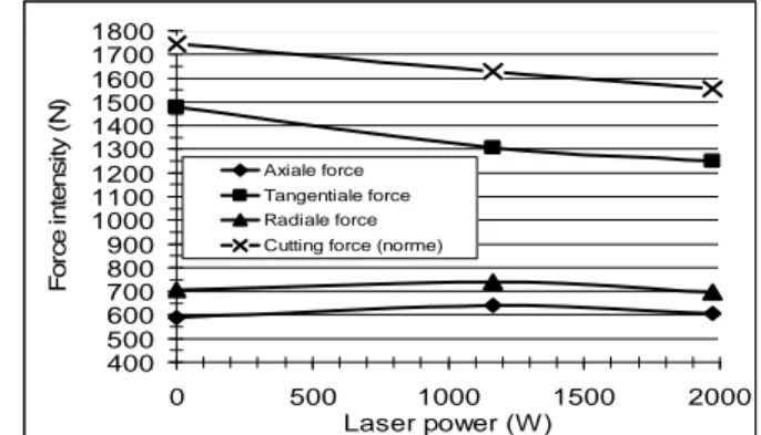
The results show a decrease magnitude of the cutting force with the laser power (Figure.3). Specifically, there is a decrease of 6.5% with a laser power of 1165 W and 10.8% with a power of 1975 W.
400 500 600 700 800 900 1000 1100 1200 1300 1400 1500 1600 1700 1800 0 500 1000 1500 2000 Laser power (W) F o rc e in te n s it y (N ) Axiale force Tangentiale force Radiale force Cutting force (norme)
Fig 3: Evolution of the three components and the magnitude of the cutting force as a function of the laser power 2.2 Surface Integrity (carbide insert)
The impact of laser assistance on the surface integrity has been quantified by the evolution of several roughness criteria and the residual stresses on the cut surface. The three surface roughness criteria used are: the arithmetic average (Ra), the maximum height peak/valley (Rmax) and the average height peak/valley (Rz). The following figure (Figure 4) shows that laser assistance can influence the surface roughness of the workpiece. A high laser power results in a slight improvement of the roughness criteria.
0 1 2 3 4 5 6 Without assistance 1165 W 1975 W Laser power (W) R ough nes s ( µ m ) Ra Rmax Rz
Fig 4: Evolution of the surface roughness as a function of laser power
The residual stresses were determined by X-ray diffraction. The analysis was carried out for the test without assistance (conventional machining - CM),
and with the maximum laser power. The values obtained are summarised in the following table (Table1).
Table 1. Residual Stresses values on the cut surface
Stress (MPa) CM LAM
1975 W Axial direction 740 ± 25 520 ± 30
Tangential direction 435 ± 45 440 ± 45
The table shows that the residual stresses on the surface are positive (tensile stresses) for the two tests. The laser assistance decreases the residual stress in the axial direction.
2.3 Tool wear (carbide insert)
These initial results demonstrate an improvement in the machinability of Inconel 718 with laser assistance. However, the improvement is modest and there is a significant drop in tool life with the use of laser assistance. Indeed, the tool life is only 50sec with the laser assistance, compared to approximately 2min 50sec in conventional machining. In both cases, the insert deteriorates very quickly with an almost instant failure of the cutting edge.
3 RESULTS OBTAINED WITH THE CERAMIC INSERT
3.1 Cutting force (ceramic insert)
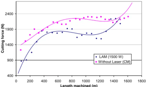
The figure below (Figure 5) shows the evolution of the magnitude of the cutting force as a function of the distance machined for both conventional machining and LAM (1500 Watts). The cutting force in LAM is lower than in CM. Depending on tool wear, the reduction in the cutting force in UAL is between 40% and 20%. 400 900 1400 1900 2400 0 200 400 600 800 1000 1200 1400 1600 1800 Length machined (m) C u tt in g fo rc e (N) LAM (1500 W) Without Laser (CM)
Fig 5: Evolution of the magnitude of the cutting force, in CM and in LAM, as a function of the distance machined
Inserts have machined respectively 1500m in LAM and 1650m in conventional machining prior to the collapse of the cutting edge. The beginning of the deteriorated area appears more rapidly in LAM (1200 m) than CM (1400 m). This deterioration
results in an increase of the radial and axial components of the cutting force, but not the tangential component.
3.2 Surface Integrity (ceramic insert)
The surface integrity was quantified by the measurement of surface roughness (three criteria: Ra, Rmax and Rz), by the determination of surface residual stresses and by examination of the cut surface with a scanning electron microscope (SEM). The three roughness criteria show the same trend. Consequently only the Ra criterion is presented in figure 6. Length machined (m) 0,0 0,5 1,0 1,5 2,0 2,5 3,0 3,5 0 200 400 600 800 1000 1200 1400 1600 1800 R o u ghness, R a (µ m ) LAM (1500W) Without Laser (CM)
Fig 6: Evolution of the surface roughness (Ra), in CM and LAM, as a function of the distance machined
It can be seen that the evolutions of Ra, in CM and LAM, are similar up to a machined distance of approximately 800 m. After this distance, the roughness is lower and less dispersed for LAM. For conventional machining after approximately 800 m, the roughness increase significantly and the data is widely scattered (scratches due to chips).
The analysis of residual stress was performed using a PROTO X-ray diffraction machine. The following table (Table 2) summarises the values of residual stress at the surface for the two types of machining.
Table 2: Surface residual stresses
Stress (MPa) CM LAM
1500 W Axial direction 160 ± 35 260 ± 35
Tangential direction 270 ± 30 555 ± 45
These values indicate that these cutting parameters result in positive or tensile residual stresses in both directions. In addition, LAM generates higher stresses due to thermal effects of laser heating. These values confirm the results obtained in other materials [9] and those found during the tests with carbide inserts.
The machined surfaces were observed with a scanning electron microscope. The figure 7 below shows pictures of the machined surfaces in CM (a)
and LAM (b).
(a) (b)
Fig 7: SEM photos of the machined surfaces in (a) CM and (b) LAM.
These photos (taken at the same magnification) demonstrate that the surface quality is considerably higher in LAM than in CM. In CM, the surface appears to be torn and dark spots, evenly distributed over the machined area, can be observed. Electron Diffusion Spectrometer (EDS) analyses were conducted to determine the nature of these dark spots. The EDS analyses show that all of the dark spots are caused by pollution of the surface by the tool insert. The presence of these elements (silicon, nitrogen, oxygen and aluminium) corresponds to a material deposit from the tool insert. This phenomenon is only visible on the conventional machined specimens. The machined parts in LAM demonstrate no such pollution.
3.3 Tool wear (ceramic insert)
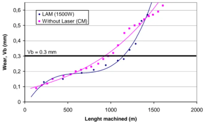
The evolution of the wear on the clearance face, Vb, is shown in figure 8, for the two types of machining, as a function of the machined distance. The evolution of the clearance wear is different for machining with and without laser assistance. In conventional machining clearance wear increases approximately linearly, while for LAM three areas of change are visible.
0 0,1 0,2 0,3 0,4 0,5 0,6 0 500 1000 1500 2000 Lenght machined (m) Wear , Vb ( m m ) LAM (1500W) Without Laser (CM) Vb = 0.3 mm
Fig 8: Evolution of wear (Vb) as a function of the machined distance
In LAM, at the beginning of machining, up to about 400 m, the wear increases rapidly (run-in). Then between about 400 and 1000 m, the wear is relatively stable in LAM. By contrast, from 1000 m the degradation of the tool is greater in LAM with a very rapid increase in clearance wear.
For a maximum wear criterion set at Vb = 0.3 mm (ISO standard), the tool life is 4min 25sec in CM and 5min 40sec in LAM.
4 CONCLUSIONS
This study, on the laser assisted machining of Inconel 718 has highlighted significant differences between the use of carbide inserts and ceramic inserts. In addition, comparisons with conventional machining were also conducted. Tests have shown that, no matter which insert is used, LAM significantly reduces the cutting force (up to 40%). The integrity of the machined surface, in terms of roughness, is not improved with the use of ceramic inserts in LAM compared to CM. However, this gain is not visible with carbide inserts. Ceramic inserts allow a very good performance during the laser assisted machining, unlike carbide inserts. In fact, the life of a carbide insert in LAM is considerably lower than its life in CM, whereas the life of ceramic inserts in LAM increase by 25% compared to the life in CM.
REFERENCES
[1] Kainth G.S., Dey B.K., Experimental investigation into tool life and temperature during hot machining of EN-24 steels, Bulletin Cercle Etudes des Métaux 14 n°11 (1980) p22.1-22.7 [2] Kitagawa T., Katsuhiro K., Kudo A., Plasma hot machining for high hardness metals, Bulletin Japon Society of Precision Engineering Vol.22 n°2 (1988) p145-151
[3] Lesourd B., Etude et modélisation des mécanismes de formation de bandes de cisaillement intense en coupe des métaux. Application au tournage assisté laser de l’alliage de titane TA6V, Thèse Ecole Centrale de Nantes (1996)
[4] Malot T., Usinage assisté par laser du bore, Thèse Université de Bourgogne (2001)
[5] Wang Y., Yang L.J., Wang N.J., An investigation of laser-assisted machining of Al2O3 particule reinforced aluminium
matrix composite, Materials Processing Technologies 129 (2002) p268-272
[6] Rebro P.A., Shin Y.C., Incropera F.P, Design of operating conditions for crackfree laser-assisted machining of mullite ceramic, International Journal of Machine Tools & Manufacture 44 (2004) p667-694.
[7] Melhaoui A., Contribution à l’étude de l’usure d’outil de coupe en usinage asssité par laser et à l’usinabilité d’une céramique à base d’oxyde de zinc, Thèse de l’ECP (1997) [8] Germain G., Lebrun J-L., Robert P., Dal Santo P., Poitou A., Experimental and numerical approaches of Laser assisted turning, IJFP Vol. 8 - Special Issue 2005, Multiscale Simulations and Experiments to optimize Material Forming Processes (2005) p347-361
[9] Germain G., Morel F., Lebrun J-L., Morel A., Huneau B., Effect of laser assistance machining on residual stress and fatigue strength for a bearing steel (100Cr6) and a titanium alloy (Ti 6Al 4V), Materials Science Forum 524-525, (2006) p559-574
![Fig. 2: Sensitivity of σ UTS to the temperature for various materials [3]](https://thumb-eu.123doks.com/thumbv2/123doknet/7301297.209164/2.892.465.799.779.965/fig-sensitivity-σ-uts-temperature-various-materials.webp)