Design of the Heliospheric Imager for the STEREO mission
Jean-Marc Defise
a∗, Jean-Philippe Halain
a, Emmanuel Mazy
a, Pierre Rochus
aRussel A. Howard
b, J. Daniel Moses
b, Dennis G. Socker
b*, George M. Simnett
c, David F. Webb
d aCentre Spatial de Liège, 4031 Angleur, Belgium
b
Naval Research Laboratory, Washington, DC 20375
cUniversity of Birmingham, Birmingham B15217, United Kingdom
d
Boston College, Chestnut Hill, MA 02467
ABSTRACT
The Heliospheric Imager (HI) is part of the SECCHI suite of instruments on-board the two STEREO spacecrafts to be launched in 2005. The two HI instruments will provide stereographic image pairs of solar coronal plasma and address the observational problem of very faint coronal mass ejections (CME) over a wide field of view (~90°) ranging from 13 to 330 R0. The key element of the instrument design is to reject the solar disk light, with straylight attenuation of the order of 10-13
to 10-15 in the camera systems. This attenuation is accomplished by a specific design of straylight baffling system, and two
separate observing cameras with complimentary FOV’s cover the wide field of view. A multi-vane diffractive system has been theoretically optimized to achieve the lower requirement (10-13 for HI-1) and is combined with a secondary baffling
system to reach the 10-15 rejection performance in the second camera system (HI-2).
This paper presents the design concept of the HI optics and baffles, and the preparation of verification tests that will demonstrate the instrument straylight performances. The baffle design has been optimized according to accommodation constrains on the spacecraft, and the optics were studied to provide adequate light gathering power and image quality. Straylight has been studied in the complete configuration, including the lens barrels and the focal plane assemblies. A specific testing facility is currently being studied to characterise the effective straylight rejection of the HI baffling. An overview of the developments for those tests is presented.
Keywords: heliospheric imager, straylight, baffling, rejection test
1. INTRODUCTION
The NASA Solar Terrestrial Relations Observatory (STEREO) mission will place two spacecrafts into nearly circular solar orbits, in the ecliptic plane, and with radii ~1 astronomical unit (AU). One spacecraft will lead, and the other will lag, the Earth’s own 1 AU orbital path and both will separate from Earth at an average rate of 22º/year over the 2-5 year mission life. The three-axis stabilised Sun pointed spacecraft carries a suite of remote sensing and in situ experiments. On the Sun Earth Connection Coronal and Heliospheric Investigation (SECCHI) experiment, the Heliospheric Imagers (HI) will cover the heliosphere out to the Earth’s orbit in white light. The HI field of view (FOV) will partially overlap the extended solar corona (COR-2 instrument) in order to provide stereographic image pairs of the volume of space extending from the Sun to the Earth. The complete SECCHI FOV also includes the lower solar corona, observed in extreme ultraviolet emission lines. The most notable scientific questions to be investigated by SECCHI pertain to coronal mass ejections (CMEs). CMEs are a class of large-scale transient phenomena revealed most effectively in white light time-series observations of the corona. They are characterised by explosive and outwardly expanding coronal density fluctuations that escape the solar gravitational
∗ Correspondence:
- Email: socker@lambda.nrl.navy.mil; Telephone: 202-767-2093; Fax: 202-767-5636
potential well and propagate into the heliosphere. SECCHI is designed to identify the processes that initiate CMEs, determine their three-dimensional structure, measure their acceleration, study their interaction with the heliosphere and explore the details of their relationship to geomagnetic storms.
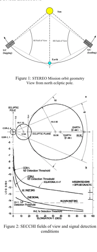
2. OBSERVATIONAL CONSIDERATIONS The STEREO mission orbital configuration (fig. 1) ensures
an ideal stereoscopic imaging instrument for optical remote sensing observation of CMEs in the region of the heliosphere from 13 Rο to 330 Rο (Earth orbit), with a nearly
hemispherical Sun centered field of view in this region of the heliosphere. The SECCHI/Heliospheric Imager (HI) described in this paper trades the very wide hemispheric field of view for a smaller field of view with superior sensitivity to the extremely faint and potentially geoeffective CMEs propagating within the heliospheric volume centered along the Sun-Earth line. It is designed to acquire a white light image data set suitable for stereographic reconstruction of CMEs propagating through the inner heliosphere near the Sun-Earth line from 13R0 to ~330R0. Detection of the CME
signal against the natural background is a strong function of elongation (ε) (fig. 2). The CME signal strength profile1
varies as R−2 to R−3 so the signal decreases about four orders of magnitude between the outer corona and ε = 90º. The sum of the electron corona and the dust corona (K+F) background brightness2 varies as R−2.25 to R−2.47 so it
decreases by about three orders of magnitude between the outer corona and ε = 90º. CME signal detection is background noise limited for all elongations, since the typical CME is ~1% of the natural background in the HI field of view. Additive instrumental backgrounds can further reduce sensitivity to the faint CME signal. Instrumental backgrounds due to stray photospheric light, cosmic rays incident on the solid state detector, improperly processed transverse stellar image motion, planets and earthshine (during the early part of the mission) are all potentially significant sources of instrumental background.
The most appropriate instrumentation for CME observation changes with CME signal detection conditions and is thus a strong function of elongation. At small elongation, the relatively bright signal, narrow required field of view, and strong photospheric and coronal backgrounds suggest an externally occulted coronagraph. On the other hand, at high elongation, the extremely low CME signal, wide required field of view, and faint night sky suggest a heavily baffled, high light gathering power (LGP), and wide-angle all-sky telescope. The HI accommodates these disparate requirements with two specialised camera systems (HI-1 & HI-2) in a nested and progressively baffled mechanical structure. Therefore, it provides the first opportunity to close the current ~320 R0 wide geoeffective CME observation gap
between the Sun and the Earth with high quality stereographic image pairs.
Earth HI Fielf of View Sun S/C (lagging) S/C (leading) HI Field of View
Figure 1: STEREO Mission orbit geometry View from north ecliptic pole.
Figure 2: SECCHI fields of view and signal detection conditions
It must be capable of detecting the extremely faint CME signal over a wide (~90°) field of view, which approaches within a few degrees of the bright solar disk and includes the bright Earth. In consequence, in the HI concept, rejection of the solar disk light is of paramount importance, since the natural object space background level (B) varies from 10-7-10-14 of the
brightness of the solar disk (B0) and the CME signal is only 10-2 of the night sky at high elongation, or 10-16 B0.
3. INSTRUMENT CONCEPT 3.1 Overview
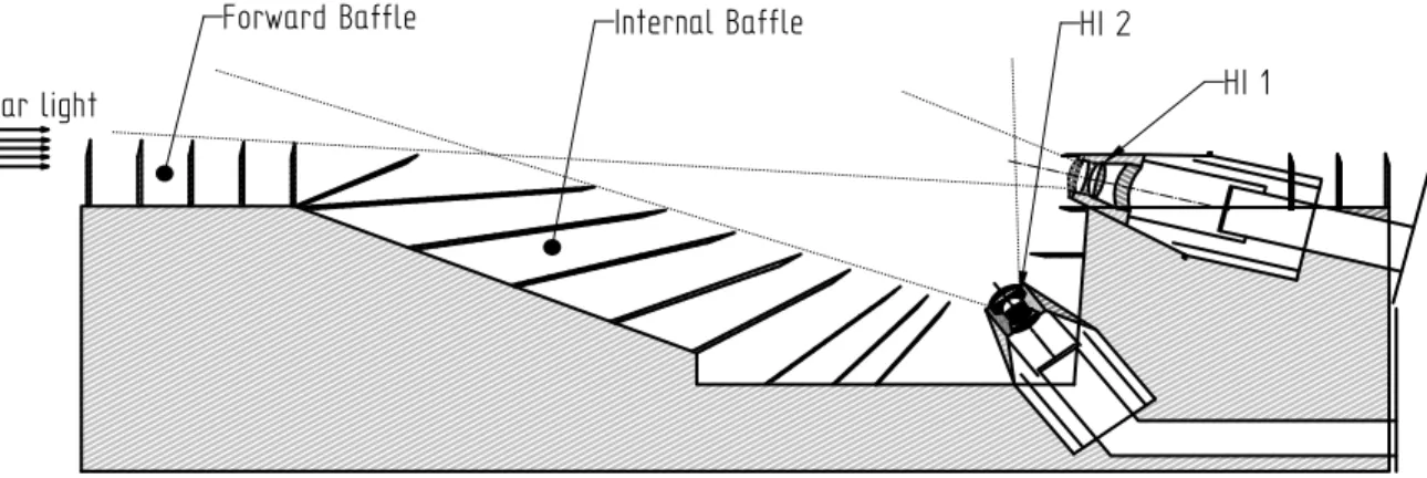
The HI instrument shown in fig 3 is mounted on a side panel of the STEREO spacecraft (S/C) whose normal is both in the ecliptic plane and perpendicular to the S/C-Sun line. HI is oriented on the panel so the optical axes of its two camera systems are in the ecliptic plane and intersect the Sun-Earth line.
Solar light
Forward Baffle
Internal Baffle
HI 1
HI 2
Figure 3: HI Design - Cut view
Due to its very large field of view (~90°), the HI field of view is shared into two camera systems, HI-1 and HI-2, with overlapping field of view, dedicated respectively for the small elongations (3.65° - 23.65°) and for the large elongations (18.36° - 88.36°) of the sky brightness. Both cameras are active at very low light level. Consequently, the key point in the HI instrument design is the optical baffles that reduces straylight to a very low level, in particular for the solar disk brightness and the Earth, located in the HI-2 field of view.
3.2 Baffle concept
Figure 4: Overall view of the HI concept
The baffle concept (fig. 4) is based on the straylight origins: the HI baffle structure can be divided in three sub-systems, each having specific function: the forward baffle, the perimeter baffle, and the internal baffle. The forward baffle is designed for the solar disk brightness rejection, the perimeter baffle for the S/C straylight rejection and the internal baffle for the Earth and stars rejection.
3.2.1. Forward baffle
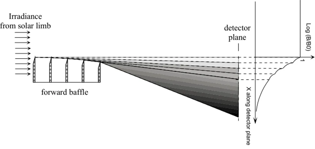
The forward baffle is used to protect HI-1 and HI-2 optical entrances from the solar light. It is similar to an externally occulted coronograph design but without a Lyot stop/spot. To reach the required rejection factor, a diffractive multi-vane baffle system was designed and optimised (fig. 5). The rejection factor of the solar disk light afforded by the forward baffle was computed using Fresnel’s second order approximation of the Fresnel-Kirchhoff diffraction integral for a semi-infinite half-screen3. Log ( B /B 0) X alo ng det ec to r plan e 1 Irradiance from solar limb
forward baffle
detector plane
Figure 5: Diffractive cascade knife-edge system
The diffraction angle is defined as the angle between the Sun limb direction and the line connecting the last vane edge and the HI-1/2 optical entrances. The critical diffraction angle for HI-1, i.e. for the top of HI-1 optical entrance (1.32°), is equally shared between each vane in order to optimise the rejection of the vane. The vane edges are arranged in an arc such that the nth intermediate vane blocks the bright linear diffracting edge of the n-1th vane from the view of the n+1th vane edge,
as shown on fig. 5. This multi-vane design is based on both laboratories tested baffle system for similar heliospheric imaging experiments and theoretical computation.
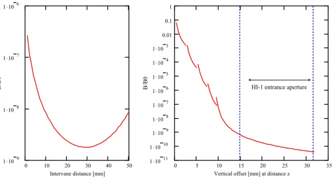
The optimisation of the forward baffle performance for the HI-1 gives a 5-vane equally spaced configuration. As shown in fig. 6, the optimal inter-vane distance is ~28.5 mm in order to minimise the integrated energy reaching the HI-1 optical entrance at 390 mm. The resulting cascading rejection curve for the forward baffle is shown on fig. 7 in the case of HI-1. The rejection level (B/B0, where B and B0 are respectively the measured and the Sun brightness) is 2.10-9 at the top of HI-1
optical entrance. As the last vane edge of the forward baffle is out of the HI-1 field of view, a supplementary 10-4 rejection
factor from the aperture stop diffraction allows the global rejection level to be lower than 10-13 at the inner field cut off, ε =
3.65° (13.67 R0) which is required to detect CMEs in the small elongations of the sky brightness regime. This is below the
natural K+F corona background in the small elongation bright sky regime and a factor of 10 better than the <10-12 B/B 0
achieved on SOHO LASCO/C31. The improvement over LASCO/C3 is due primarily to the substantially greater HI-1 inner
field of view cut-off (13.67 R0 vs. 3.8 R0) and to the fact that the Fresnel diffraction pattern intensity varies approximately
with the inverse square of the diffraction angle.
The optical entrance of HI-2 is deeper below HI-1 and the diffraction angle is larger. Therefore the rejection of the solar disk brightness is better than 2.10-12 B/B
0 at the top of HI-2 optical entrance. Taking also into account the supplementary
rejection of 10-4 from the diffraction of the HI-2 aperture stop, since the forward baffle last vane is out of HI-2 field of view,
the global rejection of the solar disk brightness at the HI-2 entrance aperture level is better than the 10-14 required rejection
0 10 20 30 40 50 1 .109 1 .108 1 .107 1 .106 Intervane distance [mm] B/B0 0 5 10 15 20 25 30 35 1 .1011 1 .1010 1 .109 1 .108 1 .107 1 .106 1 .105 1 .104 1 .103 0.01 0.1 1
Vertical offset [mm] at distance z
B/B0 HI-1 entrance aperture
Figure 6: Integrated flux into the HI-1
entrance aperture Figure 7:Forward baffle rejection curve
3.2.2. Perimeter baffle
The main function of the three-sided perimeter baffle (two laterals and one rear, fig. 4) is to protect the interior of the baffle system from solar photospheric light reflected or scattered from elements of the spacecraft located under its level. All spacecraft elements, with one exception, are required to remain below the extension of the trapezoidal baffle plane. The one exception is a single 6-meter long monopole antenna, one of the three nearly orthogonal antennas deployed by the STEREO/WAVES (SWAVES) experiment low frequency radio receiver. Calculations and ray-tracing simulations indicate that scattered photospheric light from this monopole, which is directly illuminated by the solar photosphere, will be adequately trapped by the internal part of the HI baffle system.
3.2.3. Internal baffle
The internal baffle system contains a set of vanes to catch unwanted light through diffused multi-reflections into HI-1 and HI-2 optical entrance and coming from Earth, planets, stars, zodiacal part of the sky and from the SWAVES boom. Although Earth and most of planets and stars are inside the HI-2 field of view, the internal baffle limits the uniform background onto the detector induced by diffuse reflection on mechanical support. The internal baffle system is composed by 9 tilted vanes below the forwards baffle plane (fig. 4), all of them oriented towards the top of HI-1 entrance aperture in order that both HI-2 and HI-1 entrance aperture are reached after at least 2 diffuse reflections into the internal baffle. In addition to this system, a small vane above HI-1 and a group of two small vanes between HI-1 and HI-2 are part of the internal baffle. The first one places the HI-1 entrance aperture in the shadow of the earthshine while the second protects the 2 aperture from sunshine scattering onto the above small vane. The location and size of the small vane in front of the HI-1 entrance aperture is the result of a trade off between vignetting, rejection efficiency of the forward baffle and overlapping of HI-1 and COR-2 field of view. Consequently, to ensure a 1 R0 overlap between these two fields of view, this small vane
will partially vignette the upper part of the HI-1 field of view, introducing a 0.9% vignetting in the HI-1 large elongation field of view.
1.E-21 1.E-20 1.E-19 1.E-18 1.E-17 1.E-16 1.E-15 1.E-14 1.E-13 1.E-12 1.E-11 1.E-10 0 20 40 60 80 100 120 140 160
Incidence angle [arcdeg]
B/B0
HI-1 HI-2
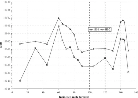
Figure 8: Internal baffle rejection
Fig. 8 shows the rejection level of the internal baffle system for straylight sources located above the perimeter baffle, computed with ASAP ray-tracing software. All surfaces included in the internal baffle system are assumed to be coated with highly diffusing black coating (i.e. Aeroglaze Z306 or similar). The ray-tracing simulation has been performed with the instrument illuminated by a collimated beam for various incident angles. Whatever the incident angle, the baffle rejection remains better than 10-12 B/B
0. Considering again a 10-4 rejection at HI-1 and HI-2 aperture stops, it guarantees a 10-16 B/B0
rejection level at both HI-1 and HI-2 focal plane.
3.3 Camera design
The HI-1 camera uses a 20º full field angle camera, slightly vignetted at its upper bound, centered at 13.65º (~51 R0) from
the solar disk and a 2048x2048 pixels CCD. The HI-2 camera consists of a 70° full field angle objective, i.e. a wide-angle fisheye lens, and a 2048x2048 pixels CCD. The HI-1 instrumental background is driven by the forward baffle efficiency while the HI-2 instrumental background is dominated by the veiling glare and diffuse scattering from earthshine diffracted at the objective aperture stop. The HI-2 instrumental background due to diffuse earthshine scattering is 5x10-15 B/B
0 for a
spacecraft-Earth lead (lag) angle of 2º (worst case) and thereafter diminishes approximately as the inverse square of the spacecraft-Earth distance. Table 1 summarises the HI-1 and HI-2 camera characteristics, and fig. 9 and 10 show respectively the HI-1 and HI-2 optical layout.
Figure 10: HI-2 optical layout
HI-1 HI-2 Field of View
Half angle 10º 35º
Center 51.12R0 (13.65º) 200R0 (53.36º)
Inner Cutoff (unvignetted) 13.67R0 ( 3.65º) 72.8R0 (18.36º)
Outer Cutoff (unvignetted) 88.58R0 (23.65º) 332R0 (88.36º)
CCD Format 2048 x 2048 x 13.5µm 2048 x 2048 x 13.5µm
Plate scale 35.15”/pixel 2.05’/pixel
Objective AR coated AR coated
Entrance pupil 16 mm 7 mm
Focal length 78.4 mm 19.74 mm
F-ratio f/4.9 f/2.8
Spectral range 650 nm - 750 nm 400 nm - 1000 nm
Instrumental background <3x10⁻¹³ B/B0 <5x10⁻¹⁵ B/B0
Nominal exposure time 12 sec 60 sec
SNR ≥30/(pixel.hr)1/2 ≥15.5/(pixel.hr)1/2
Table 1. HI instrument characteristics
The HI-1 optical design (fig. 9) is mainly driven by the size of the first lens and the entrance pupil location. The HI-1 optical axis and the depth of the HI-1 optics below the forward baffle are defined by the FOV configuration and the forward baffle efficiency constraints. The optical entrance aperture, i.e. the size of the first lens, is limited to keep large a diffraction angle and to minimise the solar disk brightness straylight diffracted by the forward baffle and entering into the optical system. The aperture stop is located as close as possible to the first lens. Glasses and coatings are chosen for their radiation resistance, particularly for the first lens. The spectral range is defined by a dedicated band-pass coating centred on 700 nm and located on an inner surface to avoid direct exposure to radiations.
The HI-2 optical design (fig. 10) is driven by the large field of view and by the veiling glares produced by bright sources inside the HI-2 field of view such as Earth, planets or bright stars. Glasses and coatings are also chosen for their radiation resistance. The HI-2 manufacturing presents some critical points such as the optical surfaces micro-roughness, glass bubble quality and anti-reflection coating. The spectral range of HI-2 is provided by the glass transmission and the CCD wavelength cut-off.
In summary, the FOV shared into 2 cameras (one dedicated for small elongation bright sky regime and the other for large elongation bright sky regime, at large diffraction angle, with additional staged baffling) will mitigate straylight rejection risk, improve threshold background noise limited signal detection at high elongation, and reduce the required overall dimensions of the perimeter baffle. The superior diffraction angle afforded the night sky portion of the field in this design is
important since solar stray light rejection is the paramount risk. This approach to technical risk mitigation was driven by the fact that the empirically determined baffle diffraction performance has not been tested before below about 10-8 for
wide-angle type diffraction baffle systems4. However Fresnel diffraction calculations indicate that the solar disk driven
instrumental background of HI is below the natural object space background for all elongations within the respective fields of view (fig. 7). This performance will be verified during straylight test as detailed in the following section.
4. STRAY-LIGHT EXPERIMENTAL MEASUREMENTS
Straylight rejection is the key element to achieve good science with the HI instrument. Light from the solar disk must absolutely be suppressed. Therefore, it is of crucial importance to evaluate as much as possible the performance of straylight rejection. The diffraction performance of multi-vane systems has not been tested before below ~ 10-8 mainly because of air
particle diffusion4. In the case of the HI instrument, the 5-vane system should produce rejection of 10-9 for HI-1 and 10-12 for
HI-2. Consequently, a vacuum straylight facility5 is currently developed at the Centre Spatial de Liège (CSL) to measure the
HI forward vanes rejection and to validate the cascading application of Fresnel theory.
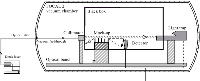
The major requirements for the vacuum facility are high cleanliness level, blackening and good mechanical stability. In order to fulfil the straylight requirement, the diffusion by particles onto the instrument environment has to be as small as possible: a class 100 clean room is required. In order to fulfil the alignment constrains during vacuum tests, the optical bench has to be vibration isolated during the test. The FOCAL 2 facility (2 m diameter, 1.35 m x 5 m optical bench) at CSL, shown on fig. 11, fulfils all these requirements.
Detector Mock-up Collimator Black box FOCAL 2 vacuum chamber Optical Fiber Light trap Optical bench Diode laser Vacuum feedthrough To cooling system Figure 11: Straylight test facility
The straylight test will be composed of two conceptual configurations. In the first case, a small optical system with a highly sensitive detector (i.e. a photomultiplier in counting mode) will point toward the last vane edge and measure the rejection level at various diffraction angles in order to verify the theoretical Fresnel analysis. In the second case, the optical system will be adapted to match with HI-1 field of view and aperture and then simulate incoming straylight into HI-1. To achieve efficient straylight detection (at least 10-9 level) and minimise the ambient background inside the vacuum chamber, high
attention is put on optical configuration and blackening.
The vanes are illuminated with an intense rectangular section collimated pencil beam produced by an external 20 CW laser diode at λ = 805 nm. A CSL designed collimator (fig. 12) isused to produce the collimated pencil beam with a minimum diffuse straylight into the vacuum chamber. The 100 mm focal length collimator optical design is driven by the location of the exit pupil: in order to avoid a direct diffuse straylight onto the detector from diffusion/reflection on the exit pupil top edge, the aperture stop is located closer of the collimator pinhole. A special light trap is designed to absorb unuseful light based on a 2-staged baffling system.
Optics Shield Specular black surface Secondary baffle Aperture stop optic fiber
Figure 12: collimator design
Conical light trqp Filter Assembly
Filter 1 Filter 2 Light trap entrance
Tube
Figure 13: Rear light trap layout
The first vane of the forward baffle mock-up is illuminated by the rectangular section collimated pencil beam. The collimator side vane surface is polished in order to specularly reflect the lower part of the beam towards a highly absorbing black surface (i.e. vacuum compatible velvet-like carbon fiber sheet).
The upper part of the pencil beam goes above the forward baffle mock-up towards a dedicated rear light trap (fig. 13). Its rejection has to be lower than 10-9 since its aperture is in direct view to the back of the forward baffle mock-up which is
itself viewed by the detector. The light trap design is based on 2 successive reflections on absorbing coloured filters and a final absorption by a classical conical light trap. The major contribution to the light trap rejection comes from the back-scattered light due to the first filter micro-roughness. As the surface micro-roughness is limited to 3 Å RMS for manufacturing limitations, the useful micro-roughness is still decreased by shadowing effect due to the high incidence angle (> 60 arcdeg). The rejection is also improved by a supplementary tube with vane. All parts, excepted the optical filters, are coated with highly diffusing black coating.
The detector consists on a photomultiplier tube with a GaAs(Cu) photocathode having 12 % quantum efficiency at 805 nm. The photomultiplier is cooled down to -15°C and used in photon counting mode in order to detect very faint signal.
All the equipment is surrounded by a black box coated with diffused black coating (i.e. MAP PU1 vacuum compatible black paint) in order to ensure a perfect black environment around the detector.
Preliminary test results
A first set of preliminary measurements was realised to compare single vane rejection level with theoretical Fresnel calculations. These measurements have been obtained in ambient air, in a black room with a 633-nm HeNe laser on a single vane set-up. The resulting single vane rejection level is shown on fig. 14 (y-axis in function of the detector vertical offset along x-axis, in mm). The dot line shows the measurement and the solid line the theoretical Fresnel curve. It shows a residual background at 10-4 P/P
0 that should be
reduced with the use of a cooled detector and the vacuum and by improving drastically the blackening of the test chamber. 5 0 5 10 15 20 1 .10 5 1 .10 4 1 .10 3 0.01 0.1 1 10
Vertical offset [m] at distance z=1m
P/
P0
5. CONCLUSIONS
An innovative design is presented for HI instrument for acquiring stereographic views of CMEs between Sun-Earth line. The straylight rejection is the critical key point that required the study of dedicated baffling systems. The ~90° field of view is shared by 2 cameras, one for the small elongations and the other for the large elongations of the bright sky regime. A 5-vane diffraction forward baffle provides adequate rejection of the solar disk brightness. A second stage diffuse baffle is used to reject of Earthshine, planets and bright stars.
Among all the performance tests required by a space instrument, specific efforts are dedicated to evaluate the straylight performances. A test set-up is being developed for vacuum measurements.
ACKNOWLEDGEMENTS
STEREO/SECCHI/HI is funded under NASA contract S-13631-Y. The Belgian contribution to the STEREO program is funded by the Federal Office for Scientific, Technical and Cultural Affairs (OSTC), in the frame of the ESA/Prodex program.
REFERENCES
1. R.A. Howard, G.E. Brueckner, O.C. St.Cyr, D.A. Biesecker, K.P. Dere, M.J. Koomen, C.M. Korendyke, P.L. Lamy, A. Llebaria, M.V. Bout, D.J. Michels, J.D. Moses, S.E. Paswaters, S.P. Plunckett, R. Schween, G.M. Simnett, D.G. Socker, S.J. Tappin, D. Wang, “Observations of CMEs from SOHO/LASCO,” Coronal Mass Ejections, N. Crooker, J.A. Joselyn, J. Freeman, editors, The American Geophysical Union, pp. 17-26, 1997.
2. S. Koutchmy and P.L. Lamy, “ The F-corona and the circum-solar dust evidences and properties,” in “Properties and Interactions of the Interplanetary Dust,” IAU Colloq. 85, pp. 63-74, 1985.
3. M. Born and E. Wolf, Principles of Optics, 6th (corrected) edition, Pergamon Press, New York, 1980.
4. Buffington, A. Jackson, B.V. and Korendyke, C.M., “Wide-angle stray-light reduction for a spaceborne optical hemispherical imager,” Applied Optics, 35, No. 34, pp. 6669-6673, 1996.
5. J.-M. Defise, J.-P. Halain, E. Mazy, P. Rochus, "Straylight tests for the Heliospheric imagers of STEREO", ESA-SP-467, 4th International Symposium on "Environmental Testing for Space Programmes", June 2001.
