A 3-D DISPLAY HEAD-SET FOR PERSONALIZED COMPUTING
by
Mark A. Callahan
B.E.D., Miami University Oxford, Ohio
(1979)
Submitted to the
Department of Architecture in Partial Fulfillment of
the Requirements for the degree of
Master of Science in Visual Studies
at the
Massachusetts Institute of Technology June 1983
Massachusetts Institute of Technology 1983
Signature of Author. Certified by . . . . Accepted by. . Department of Architecture February 8, 1983 . . . . . . . . . . . . . . . . . . . . Andrew B. Lippman Assistant Professor of Media Technology Thesis Supervisor
. . .. . . . . . . . . . . . . . . . , .
Professor Nicholas Negroponte, Chairman Departmental Committee for Graduate Students
r
otC
O
MSSACHUSE TS INSTIfurtOF TECHNOLOGY
A 3-D DISPLAY HEAD-SET FOR PERSONALIZED COMPUTING
by
Mark A. Callahan
Submitted to the Department of Architecture on February 8, 1963, in partial fulfillment of the requirements for the degree of Master of Science in Visual Studies.
ABSTRACT
This thesis covers the design and implementation of a
binocular display head-set akin to Dr. Ivan E. Sutherland's head-mounted display, but using several new technologies
and new techniques in computer graphics: small portable video display, transmitter and receiver; write-once optical video disc recorder; a magnetic position sensor, and a
depth cue based animation package. This implementation has permitted the creation of a highly interactive three
dimensional trainer / simulator.
Computer generated controlled images are optically mixed into the surrounding environment by imaging through two beamsplitter mirrors positioned in front of the viewer's eyes. The source of the images on the display head-set is two Sony Flat CRT's mounted on top of the head-set pointing downward. The beamsplitter mirrors are angled out from the bottom of a pair of eyeglasses. Normal vision is through the eyeglasses; the TV images are reflected in the mirrors. The viewer is able to manipulate the display image by
"touching" and "moving" the image with his hand, or even to "look around" the display image. A position sensor located on either the viewers hand or the head-set itself provides the input for the manipulation. Stereo for 3-D viewing is obtained by transmitting two video sources to the two
receivers on two UHF channels located in a small beltpack. This thesis also describes a write-once optical video disc
recorder that is used to store "pre-computed" view-point dependent images. The images of a scene were recorded in coherent segments to create a visual data base; included were full rotations and general movements of stereoscopic
image pairs. Real-time manipulation of the pre-recorded images is done though fast-excuting commands on the optical
write-once recorder. The graphics package permits quick construction and scripting of objects. To increase the sensation of 3-D, special attention is paid to the
inclusion and the highlighting of physiological and psychological depth cues.
Thesis Supervisor: . . . Andrew B. Lippman
Title: Assistant Professor of
Media Technology The work reported herein was supported by the Advanced Research Projects Agency of the Department of Defense, Defense Sciences Division under Contract number MDA
TABLE OF CONTENTS
page
ABSTRACT . . . - -. .. . . . . . . . . . . . . . .2
TABLE OF CONTENTS . . . . . . . . . . . . . . . . . .5
1.0 Introduction . . . . . . . . . . . . . . . .7
2.0 Video Display Technology . . . . . . . . . .12
3.0 Input Devices. . . . . . . . . . . . . . . .18
4.0 The Graphics System. . . . . . . . . . . . .24
4.1 Optical Storage. . . . . . . . . . . . . . .26
4.2 Pre-Computed Images. . . . . .. ... 29
4.3.0 Depth Cues . . . . . . . . . . . . . . . . .30
4.3.1 Binocular Parallax and Convergence . . . . .34
4.3.2 kinetic Depth Effect . . . . . . . . . . . .34
4.3.3 Relative Motion. . . . . . . . . . . . . . .35
5.0 Qualities of Display Systems . . . . . . . .37
5.1 Portability . .. . . . . . . . . . . . . .37
5.2 Unobtrusiveness. . . . . . . . . . . . . . .38
5.3 Stereo . . . . . . . . . . . . . . . . . . .39
5.4 Virtual and View-Point Dependent Imagery. . . . . . . . . . . . . . . . . . .41
6.0 Design of the Display Head-Set: Displays . . . . . . . . . . . . . . . . . .43 6.1 Plastic Casing . . . . . . . . . . . . . . .46 6.2 Helmets. . . . . . . . . . . . . . . . . . .51 6.3 Adjustibility. . . . . . . . . . . . . . . .53 6.4 Shielding. . . . . . . . . . . . . . . . . .54 6.5 beltpack . . . . . . . . . . . . . . . . . .55 6.6 Optics . . . . . . . . . . . . . . . . . . .55 6.7.0 Configuration. . . . . . . . . . . . . . . .58
6.7.1 The Final Configuration. . . . . . . . . . .61
6.8 Head-set Limitations . . . . . . . . . . . .66
7.0 System Implementation. . . . . . . . . . . .68
7.1 Transmitting to the Display Head-Set . . . . . . . . . . . . . . . . . .68
7.2 Video Generation . . . . . . . . . . . . . .71
7.3 Location - Media Room. . . . . . . . . . . .71
7.4 Controlling Software . . . . . . . . . . . .73 7.5 Dynamic Images . . . . . . . . . . . . . . .74 7.6 Static Images. . . . . . . . . . . . . . . .76 7.7 System Limitations . . . . . . . . . . . . .77 8.0 Virtual Imaging. . . . . . . . . . . . . . .80 8.1 Is Stereo Necessary. . . . . . . . . . . . .82
9.0 Applications . . . . . . .
.
.
. .
.85
10.0 Future Extentions. . . . . . . 10.1 Eye Tracking . . . . . . . . . 10.2 Sound. . . . . . . . . . . . . 10.3 The Glove. . . . . . . . . . . 10.4 Voice Input. . . . . . . . . . 11.1 Proposal for the Next DisplayHead-Set . . . . . . . . . . . 12.1 Conclusion . . . . . . . . . . APPENDIX I . . . . . . . . . . . . . . REFERENCES .. - ... ... ACKNOWLEDGEMENTS . . . . . . . . . . . .87 . 87 .89 .90 .93 .95 .100 .104 .106 .110
1.0 Introduction
"We live in a physical world whose properties we have come to know well through long familiarity. We sense an involvement with this physical world which gives us the ability to predict
its properties well. For example, we can predict where objects will fall, how well known shapes look from other angles and how much force is required to push objects against friction. We
lack corresponding familiarity with the forces on charged particles, forces in nonuniform fields, the effects of
nonprojective geometric transformations, and high-inertia, low friction motion. A display connected to a digital computer gives us a chance to gain familiarity with concepts not
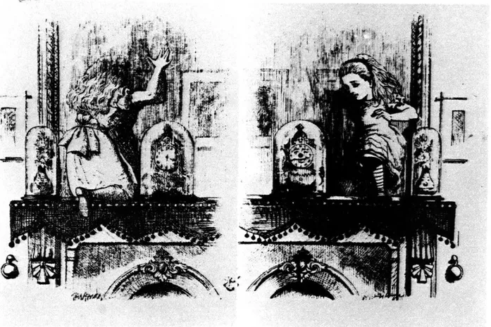
realizable in the physical world. It is a looking glass into a mathematical wonderland." [see figure 1,2]
- Ivan E. Sutherland, "The Ultimate Display", IFIP, 1981.
Ever since construction of the MARK I, the first digital computer in 1944, scientists have been searching for ways to create the looking glass, as referenced by Ivan
Sutherland in the above quote. Even though computer technology has progressed rapidly, there still exists a real need to design computers that can be used by ordinary people unversed in computer dogma. one important goal in computer development must be to display and communicate
information in a way that becomes second nature to the user. To aquire familiarity with information, the presentation of it must be intrinsic and must spontaneously conform to how the user wants the information, not how the computer
requires it.
Much of this thesis is concerned with the technology of a particular 3-D image display akin to Sutherland's "looking glass", but updated. However, the large context is the development of interactive techniques for personal
computing. The rapid development of personal computers has rekindled interest in intuitively clear human-oriented
peripherals. Further, these interactive and display technologies are targeted at the consumer market, making them inexpensive enough for widespread use.
instrumental in the development of information displays and communication systems. Historically, personal computation has been based on the emergence of two fields; interactive computer graphics and the personal computer. Ivan
Sutherland's thesis, SKETCHPAD, in the early sixities was the first formal attempt to use computation for graphical
communication between man and machine
[40].
Interestinglyenough, in a field characterized by ultra-rapid change, it is remarkably cogent and relevant today. The goal of
SKETCHPAD was to build a computer system that allowed a user to interact with a computer through graphics, a light pen, and a keyboard; something that architects, designers and engineers would be more familiar and comfortable with than numbers. Computers at the time of SKETCHPAD were expensive and large, and Sutherland's work was as much a technical and conceptual tour de force as a prototype example. However, the 70's introduced a new computer
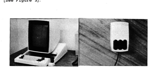
doctrine and architecture based around a low cost and power single user computer -- a personal computer. One of the first truly personal computers was developed at Xerox Palo Alto Research Center by Alan Kay and associates in the
early 70's [17]. Their personal computer was a very
interactive system with a user oriented operating system (smalltalk), a high resolution black and white screen, a keyboard and an interactive input device called a "mouse"
[See Figure 3].
Figure 3. BYTE, McGraw-Hill, August 1981.
The last few years have seen increased interest in 3-D
technologies. In part, the interest in 3-D has been caused
by the development of other unrelated new and emerging
display technologies, such as "PLZT" optical-electrical
devices and miniaturized video systems [10]. The
increasingly wide-spread use of these recent technologies, especially in commercially available products, has impelled work on the development of the display head-set. Of
interest is not solely the display head-set itself, but its integration with training and information systems, all
within a personalized computing environment.
has differed from other implementations of head-mounted displays. By using several supposedly unrelated
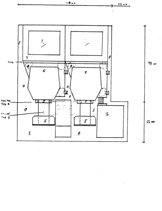
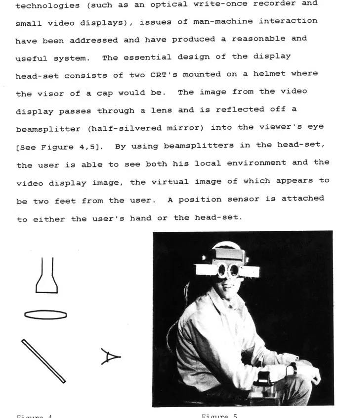
technologies (such as an optical write-once recorder and small video displays), issues of man-machine interaction have been addressed and have produced a reasonable and useful system. The essential design of the display
head-set consists of two CRT's mounted on a helmet where the visor of a cap would be. The image from the video display passes through a lens and is reflected off a
beamsplitter (half-silvered mirror) into the viewer's eye
ESee Figure 4,5]. By using beamsplitters in the head-set,
the user is able to see both his local environment and the video display image, the virtual image of which appears to be two feet from the user. A position sensor is attached to either the user's hand or the head-set.
2.0 Video Display Technology
rWAS rHAT C.HIe CLI#MER
WHO STEAAAE
SV
METHe
Tr SpURE WAS, Ole-)
Small, portable displays seem to be the result of two basically different approaches: advances in CRT design,
and alternatives in CRT design. Although most of the
attention has been given to thin, flat solid-state designs, there has resently been interest in "wierd" CRTs. As an example, the Panasonic Travelvision black and white
television has a miniature CRT with a 1.2 inch diagonal
screen [See Figure 7]. More radical departures derived
from contemporary CRT's are the Sony and Sinclair video displays, which are flat because of the placement of the electron gun perpendicular to the phosphor display surface
[3] [See Figure 8]. The above televisions are being marketed
in the USA and Japan $120.00 - $300.00. They are more than just a novelty because of the exceptionally good quality and resolution and, more importantly, because they are thin and flat. Individuals can take these small TV's with them to watch their favorite television series or a rerun of M.A. S.H.! Color video displays are also being reduced in size and weight. Panasonic has a color portable television with a 2.6 inch diagonal screen for under $500. While these displays are having an immediate impact on the CRT market, long term use may decrease because of the availability and development of solid-state displays. For the display
Figure 7.
/00%4k%
Figure 8B. Figure 8A.
instead of waiting for availability of solid-state display.
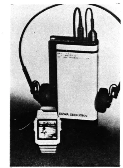
Figure 9. Seiko Group, "Wristwatch TV", Electronics, June 30, 1982
Solid-state displays are based upon a totally different set of technologies than the contemporary CRT. Many individual solid-state technologies exist within this broad category, such as liquid-crystal displays, vacuum fluorescent
electrochromic displays [41,22]. Common among these
solid-state displays are their flat screens, thinness, and a potentially low production cost. Liquid-crystal displays will have the first major impact on the video display field. Shortly, the Dick Tracy comic fiction will become reality with the introduction early in 1983 of the Wristwatch TV by
the Seiko Group in Japan [2] [See Figure 6,9]. A 1.2 inch
diagonal liquid-crystal display is housed in a wristwatch along with the normal functions of the watch, such as time and alarm. The cost of the Wristwatch TV will be around $400. In addition to Seiko, other Japanies companies will be introducing similar displays. These liquid-crystal
displays come very close to matching the Panasonic and Sony CRT'S in resolution and contrast.
Just as the technology for solid-state displays are
different from contemporary displays, so are their inherent qualities. The most apparent quality of solid-state
displays is thinness. The actual display area is a good estimate of its total size, where as, in the elongated CRT displays, the actual display is but a small part of the total CRT surface. Flatness is another quality found in solid-state displays but not normally found in CRT's,
except for the Sony and Sinclair video displays. There are many applications where contemporary CRT's can not be used
because the displays are slightly curved. What these qualities do is to greatly improve the ability to embody displays in different and innovative ways; like a display head-set visor, a note pad, or part of a desk surface.
Qualities of solid-state displays vary between individual technologies. As an example, one of these differences is the non-emissive quality of liquid-crystal displays. The LCD display can be thought of a as paper as compared to contemporary light generating displays. What happens if there is no light? Other solid-state displays generate
light (like a plasma panel), but in turn, have different associated qualities and features.
3.0 Three-Dimensional Input Technology
The selection of an input device is an important
requirement for integrating any display screen into a useful interactive system. Today there are many input
devices available. Most return two-dimensional coordinates. Examples are touch sensitive screens, data tablets and
track balls. They capture the style of interaction
normally associated with pencil and paper. Occasionally, however, it is useful to manipulate with a display using all possible degrees of freedom.
The display head-set uses two forms of three-dimensional input; first for head tracking, and second for use by the user's hands. The head tracking data is important for up dating the displayed image and as a crude estimate of where
the user is looking. The hand held input device can be used for user directed input, such as pointing or
interacting with the displayed image. A further use of a hand held three-dimensional input device is for gesture
recognition [6].
To date there have been many approaches to
three-dimensional digitizing and position sensing, none of which stand out as totally successful; all have their own
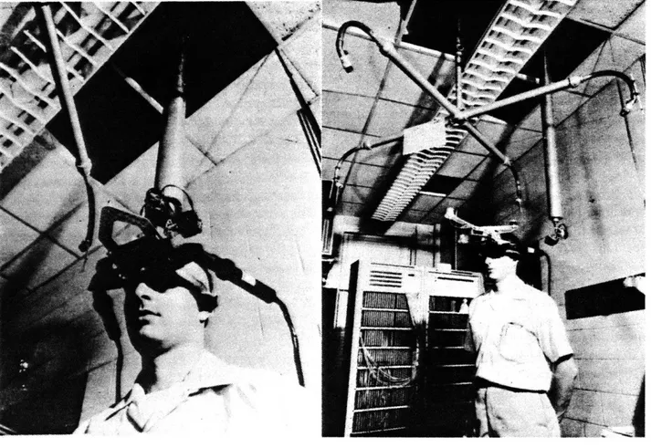
advantages and disadvantages. The most brute force method of three-dimensional input was a mechanical arm attached to
Sutherland's head mounted display E38] [See Figure 10].
The mechanical arm converted head movements into
translations and rotations within a confined area. The mechanical arm was very uncomfortable to use because of its weight and the physical connection with the head-mounted
display.
Sutherland's group also experimented with two ultrasonic three-dimensional input devices; one a head tracker, and the other a hand operated digitizer. The head tracker was designed to replace the the mechanical arm, and was
designed at the MIT Lincoln Laboratory by Charles Seitz and
Stylianos Pezaris [See Figure 11]. The input device used
three transmitters attached to the helmet and four receivers separately located above the helmet. The
transmitters continuously transmitted ultrasonic sound for reception by the receivers. The hand held 3-D input device
was called the Lincoln Wand [33]. The Wand, when activated
by the user's touch, emitted a short pulse of ultrasonic sound detectable by the receivers. From the correlation of all four receivers the 3-D position of the Wands was
The major problem with ultrasonic devices, especially the above devices, is the occurrence of random sounds
corrupting the three-dimensional data. Most of these random sounds are unavoidable in any but the most
controlled environment. In addition, ambient temperature, motion, local reflections and humidity all effect data
recovery [27, 28]. As an example, the Lincoln Wand was
susceptible to sounds emitted from typewriters. Even today ultrasonic devices are susceptible to random sounds.
Another more humorous example of this happened while I was attending a manufacturer's convention. A vendor was
demonstrating the use of a new ultrasonic digitizer by digitizing a plastic model of an airplane. As the salesperson digitized, a graphics terminal displayed a
splined version of his 3-D data. The digitizer worked fine until the sales person sneezed!
Supplying the position and attitude input for the display head-set is a true three-dimensional magnetic position sensing device manufactured by Polhemus Navigational
Sciences (nicknamed the Polhemus)[31]. The
three-dimensional digitizer consists of two devices; a radiator, which sets up the magnetic field, and the small
sensor [See Figure 12]. The small sensor is attached by a
connected to a dedicated controlling computer. This computer returns the sensor's position (x, y, and z) and the attitude (azimuth, elevation and roll) forty times a second. For accurate data the sensor must be within a four foot radius of the radiator.
Figure 12.
As with other three-dimensional digitizers, the Polhemus has limitations. Within the four foot radius of the
radiator data can be corrupted by external magnetic fields, such as that produced by the yolk of a CRT display. To limit this interference, all devices producing magnetic
4.0 Graphics
Work on the animation system that generated pictures for the display head-set began in the summer of 1982. The goals of the implementation were as follows: to allow easy construction of small three-dimensional entities; to allow the combination of these entities into larger objects; to
include a separate instruction set with each entity or
object for animation, and to provide the options for stereo or PLZT image generation and storage on to the Panasonic Optical Write-Once Recorder,
An important consideration in the animation package was the data structure for the three-dimensional entities and
objects. The structure had to incorporate both a system to combine entities into objects and to provide animation
instructions. Instead of using one large data structure, three smaller structures would be used to statisfy the above requirements. They are:
name.data name.control name.path
data. Name.path contains frame-to-frame transformation data for the animation. Lastly, name.control contains
information about the structures, plus pointers to other control structures, permitting the building of entities into objects.
The package was implemented on a Perkin - Elmer 32 bit computer running magic6 (a home grown operating system at the Architecture Machine Group) and programmed in PL/1. Several different frame buffers were used throughout the project. These included: Ramteck 640 x 490 x 9; AED 512 x
512 x 8; and later a Raster Technology 512 x 512 x 24. The application software was device independent. For input, the graphics system used a touch sensitive screen, data
tablet, and in one instance, the Polhemus position sensor.
For hidden surface removal, the furthest surface away from the viewing plane was drawn first; thus the closer surfaces painted over the surfaces further. This straight forward painter's algorithem was chosen because of its ease of implementation and its lack of complexity. However, it soon became apparent that a three-dimensional clipper would be needed to reduce the needless time consumed in drawing
invisible polygons; the image generation time was reduced by the three-dimensional clipping. An alternative approach
for hidden surface elmination is the use of a Z buffer. Only a bits of the Raster Technology frame buffer's 24 bits will be used to hold the image. The remaining 16 bits of the Raster Technology frame buffer will hold a Z depth
value for determining hidden surface pixel by pixel. The Z buffer will greatly improve the image quality at edges or
at the intersection of objects.
The first test of the graphics system illustrated several problems with the system. First, the objects formed by
polygon surfaces were unattractive [See Figure 13]. Image
quality could be improved by increasing the number of polygons, but image generation time would be increased to
an unacceptable level. Instead of drawing more polygons, smooth surfaces were generated by interpolating the
vertices' color values to produce intermediate colors in the polygon area. This approach actually produced a smooth surface with fewer polygons and at a reduced image
generation time.
4.1 Image Storage
Computer generated images were stored on a Panasonic
Optical write-Once Recorder [See Figure 14]. The recorder
Figure 13.
...
4: .44.4
recording density of 15,000 individual video frames. The Panasonic uses standard NTSC as input for recording and output in play back mode. The Panasonic records in real-time (one thirtieth of a second), but requires a full-half second for cool-down before the next frame can be recorded. The Panasonic Recorder, because of an
improved drive, has search times substantially shorter than the standard industrial video disc player currently
available.- Maximum search time on the Panasonic Recorder from frame 1 to frame 15,000 is less than two seconds. Computer control is provided through a serial port on the Panasonic Recorder. Commands include: search to, step
forward, step back, read frame number, and record.
A problem found in the first test was the importance of the color map selection. Many of the color values used in the first test were too "hot" to record on the sub-NTSC
Panasonic Optical Write-Once recorder. The poor color selection made even more noticeable other limitations such as drop-outs. The solution to the color selection problem was to generally reduce the intensity of the colors in the color look-up table of the graphics frame buffer.
4.2 Pre-Computing Graphics Images
A large portion of the time spent during Ivan Sutherland's head mounted display project was devoted to building and
debugging a hardware real-time 3-D vector processor. Fourteen years later, real-time graphics processors are
still difficult to build and expensive to purchase. The solution was to retrieve in real-time stored, pre-computed video images. This approach was chosen because of
experience with video disc, especially The Movie Map23].
This project photographed the entire city of Aspen,
Colorado, and recorded it on optical video disc. Using the Aspen video disc as a visual data base, an interactive
system was developed which permitted a user to visually drive through the city. Also influencing the decision was the arrival of the Panasonic Write-Once Optical Recorder which has a sophisticated drive mechanism permitting fast
searches. In many situations, there is no longer a need for a dedicated real-time graphics processor, only the fast search video disc player and a optical disc with the
pre-computed images.
The main trade-off when using pre-computed images is the limited number of movements and alternatives available to the user. Therefore, the selection of those images becomes
critical to the eventual success of the system. For the display head-set project, all possible movements and
alternatives were compared with the time limitation to actually generate the required animation. Additional time was then needed to determine the actual frame-to-frame
location of the animated segments on the optical disc.
Several sets of pre-computed view-point dependent animation were recorded on the Panasonic Optical Write-Once. The first set of animation contained two full rotations (120 frames each), of a molecule, plus 60 frames of several bonds changing states. Animated next were several short segments ranging 60 frames each of a field of objects, such as a 180 degree turn, movement left to right, and front to back. All animation was generated and stored in stereo
[See Figure 15,16J. Figure 17 is an illustration of where
the images were stored on the write-once.
4.3.0 Depth Cues
The three-dimensional sensation found in stereo displays or on highly dynamic three-dimensional raster graphics systems is caused by visual depth cues. It was therefore important to consider and take full advantage of these cues when
Figure 15.
Optical Write-Once Disc Log First set 191 192 309 Second set 311 371 372 491 492 609 Figure 17. 3411 3470 3471
3500
3501 3591 3601 3660 3661 3690 3691 3780human visual system uses depth cues for determining the depth, shape and spatial orientation of objects in the
visual field [14]. The selection and emphasis of visual
depth cues for use in a particular application must depend upon the kind of imagery to be generated and the target display hardware. As an example, the optimal combination of depth cues will differ between imagery for a display head-set and a monocular vector display, just as the optimal combination of cues will differ in dynamic verus static imagery.
With or without the designer's knowledge, visual cues are present in any information display. However, cues found in
images are not necessarly "depth" cues, and could reduce or destroy the effect of real depth cues. The use of
incorrect or unknown depth cues will result in anti-cues inhibiting any three-dimensional sensation. A depth cue becomes an anti-cue whenever it occurs contrary to other cues. Several depth cues were used in and experimented with in the animation done. They are binocular parallax, convergence and motion cues, along with perspective imaging and hidden surfaces.
4.3.1 Binocular Parallax and Convergence
Depth cues fall into two categories binocular and monocular. The binocular depth cues are binocular parallax and
convergence, and are used as depth cues in stereoscopic
display systems. Binocular parallax and convergence are
among the strongest depth cues and are both effective up to
30 feet [30]. Binocular parallax occurs when two
dissimilar images of the same view are simutaneously
displayed to each eye. The effect of the cue is caused by the displacement of both images on the eye's retina.
Convergence, like binocular parallax, is present in stereo displays and uses the same mechanisms. Convergence is the angle made by intersecting rays extending from the
observer's eyes to the point where the observer is looking. In most of the animation the closest synthetic object was made to appear a little more than two and one half feet
away from the user.
4.3.2 The Kinetic Depth Effect
When an observer views a two-dimensional projection of a moving three-dimensional object, he will normally perceive
the projection with depth. This effect of perceiving depth
Kinetic Depth Effect" [48). Several studies have shown
that the kinetic depth effect is a powerful factor in depth perception and is therefore important in three-dimensional
computer graphics [12,13].
4.3.3 Relative Motion Cues
The relative motion cue is dependent upon a reference point, with either a field of objects moving while the observer is stationary or with the observer moving and the field of
objects stationary. As an example, a distance cue is
created from the relative motion of objects because of the assumption that distant objects should be moving at a
slower rate than closer objects.
Another motion cue is provided by the motion of the
observer when viewing objects. As the observer moves, the objects remain view-point dependent and are thus seen in the correct perspective. As an example, the display
head-set with attached position sensor can be used in the above fashion by up-dating the display with view-point dependent images. Any system that can generate real-time perspective images can potentially use this cue by adding a three-dimensional position sensor. However, real-time
this motion cue by creating a theoretical observer with his eyes being the graphics screen. Anti-cues will result when the real observer moves his head and senses no
5.0 Display Systems
The following is a look at qualities of head-mounted and
heads-up displays that were used as benchmarks and goals
for the design and implementation of the display head-set discussed in this thesis. These qualities are unique and are only now being implemented in general display systems. They are: portability, unobtrusiveness, stereo, and virtual and view-point dependent images. Highly customized
head-mounted and heads-up display systems are discussed that exhibit these qualities. Some of these systems have displays mounted on helmets, while others mount only
lightweight shutter mechanisms and locate the video source several feet away from the wearer. However, all these dissimilar technologies and techniques provide qualities that have not previously been associated with computer
displays.
5.1 Portability
What is portability? The most obvious answer is a display
that you can literally carry with you: VIMAD (Voice
Interactive Mantenance Aiding Device) is with out a doubt an example of such a system. VIMAD was developed to assist in the maintenance and repair of military equipment in the
field. VIMAD consists of a head-set, beltpack, keyboard,
and a remote personal computer / video disc system E44].
The helmet contans a single video display located above the right eye, an earphone and microphone. Directly above the right eye is an adjustable mirror used for custom
positioning of the reflected video image by any user. Cables connect the helmet to the beltpack where the transmitter and receiver are located.
The goal of VIMAD is to provide audio and visual instructions for repair and maintenance of military
equipment in the field. The VIMAD concept was developed to replace text manuals because of their bulkiness and the high illiteracy rate in the Armed Forces. The training material has been placed on optical video disc and is controlled by a personal computer, but because of VIMAD's portability, the computer equipment does not have to go with the user.
5.2 Unobtrusiveness
very close to portability in importance is the need for the display to be unobtrusive. As an example, the head-mounted or heads-up displays used by pilots (for the sake of the crew) have to be unobtrusive. The physical presence of
these displays must not adversely affect the pilot's
ability to fly the aircraft. Furthermore, the systems must be designed to provide information in an instintive format, since the pilot viewing information must make instantaneous decisions, and thus cannot be bothered by the "presence" of the display devices or the displayed image. Various designs for such head-mounted or heads-up displays have been
implemented for pilots [9,15,36] [See Figures 19,20). While
the success of most of these displays has been limited to the very confined area of a cockpit, some display devices have introduced truly innovative designs. The most
interesting of these is a micro-display that uses a small reflective surface placed in eyeglasses to reflect an
optical image into the user's eye [43].
5.3 Stereo
Different display techniques in many applications are needed to maximize the reception of information; one
example of this has been the display of three-dimensional
stereo [20]. The PLZT viewer is a head-set system which
allows stereo. The head-set consists of electronically
controlled optical shutters [see figure 21]. A
three-dimensional sensation is obtained when the user views a specially composed video source where the two video
Figure 19.
Figure 21.
fields contains separate left and right perspective views of an image. Each eye sees a different perspective image by synchronizing the optical shutters on the head-set with
the video field rate [4].
Once the PLZT viewer is integrated into a graphics system, it becomes a useful tool for three-dimensional viewing in
applications such as simulation and modeling [34,35]. This
can include a personalized three-dimensional workstation where the user is given greater flexiblity of movement plus
3-D. Such a workstation has been designed using a very large half-silvered mirror to reflect a PLZT stereo image
for the observer wearing the PLZT head-set [37].
5.4 Virtual and View-Point Dependent Imaging
Sutherland's head-mounted display implementation in 1968 was the first to include the display of virtual and dynamic view-point dependent images. The head-mounted display
consisted of two miniature cathode ray tubes and display
optics including beamsplitters [See Figure 22]. The cRT's
presented a separate image to each of the user's eyes. As was discussed in Chapter 3 a head tracker gathered data for generating display imagery.
Figure 22.
Sutherland's head mounted display could superimpose images into the user's own environment. The optical beamsplitter reflected the video image into the user's eyes, but still permitted the user to see through into his own environment.
A large portion of the project development time was
dedicated to building hardware for real-time display. Combining the head-set, head-tracker, and the real-time
display hardware a user can look around or walk around a three-dimensional image. The believability of the
displayed images was improved because of the real-time calculations of view-point dependent images.
6.0 Design Of The Display Head-Set: The Video Displays
There have been three generations of display head-sets in the project. The evolution has been mainly dependent upon the use of the video display device. The video displays used in the first display head-set were taken from two Panasonic Travelvision televisions. This particular display is black and white and has a 1.2 inch diagonal
screen CSee Figure 23]. The complete Travelvision
television set is 6 by 3 inches including tuner and four penlight batteries, as discussed in Chapter 2. To make the televisions usable, the video displays were extended by
about four feet from the tuner and power supply. To extend the video display from the Panasonic PC boards, nine wires were lengthened; three from the fly-back transformer and six directly from the PC boards. A shielded coaxial cable was used instead of the thinner type wire found in the Panasonic TV. The high voltage line was arranged
separately using high voltage cable. A grounded shielding was used to prevent possible interference, especially by the magnetic position sensor. Also, two cable connecters were added to allow easy interchange of displays. Once the video displays were mounted, the remainer of the
The other two display head-sets used two Sony Flat TV's for receiving and displaying video images. The Sony Television
is similar in gross size and function to the Panasonic television, being 7 by 4 inches with a black and white 2
inch diagonal screen [See Figure 24]. However, the
innovative difference, as its name suggests, is that the Sony television is flat. The display is not a solid-state display, but is based on standard CRT technology. To
obtain the flatness, electrons from the CRT gun are bent 90 degrees onto a phosphor surface. The viewer looks through a glass window to see the video image, since the phosphor
surface is located on the far side of the CRT ESee Figure
eb].
As with the Panasonic video displays, the Sony video displays were also extended several feet away from their driving PC boards and power supplies. Extending the Sony video displays from the other components was more difficult because of its highly engineered packaging. We literally held our breath when soldering the Sony PC boards for fear
of damaging them. Also, complicating matters was the fact that there was no service manual available for the Sony Flat TV (The Sony Flat TV's were purchased in Japan).
Figure 23.
and the video display were left intact because of the difficulty of cutting and resoldering these very short
cables. Thus, the fly-back transformer had to be mounted
on the display head-set next to the video displays. The
transformers added a little extra weight to the head-set and made designing a cradle to hold the displays a bit more difficult, but made extending the displays straight forward. Seven additional wires were needed to completely extend the
video displays. The major problem was contending with
soldering the new longer wires onto the Sony PC board without damaging or shorting-out a component.
6.1 Plastic Casing
Determining the most effective way of mounting and
positioning the video displays took a considerable amount of thought and was critical to the success of the display
head-set. This system or approach had to statisfy many
requirements to be successful. First, the video displays had to be totally enclosed, proventing outside ambient
light from reducing image quality of the light generating displays. Next, the structure had to be strong and rigid enough to hold the displays and optics, yet the entire structure had to be as light-weight as possible, since it would be resting on a user's head. Lastly, the structure
had to be easy to build and modify; since it was obvious
that the first head-set would not be the last or even the best.
The approach used for design and construction of the display head-set was to divide it into two sections, a helmet and separate attachable casing. The casing would cradle and protect the video displays and optics. Normally the helmet would not be modified, but the casing containing the video displays and the optics would be modified
repeatedly. This way, a new modified casing could be simply interchanged with a older casing without effecting the helmet or lengthening the head-set down time. To make this down-time as short as possible, it was decided that the casings would be made out of molded plastic. A
modification to the head-set entailed modifying a separate model of the casing and then using that model to vacuum mold a new plastic casing.
The plastic casing was constructed by first cutting out a wood model of the casing. The model was cut out to the exact dimensions of the real casing minus one millimeter or so to account for the thickness of the molded plastic. As an example, Figure 25 is a wood model of one of the first head-sets using the Sony displays. On the head-sets using
Panasonic displays, the model was first cut into two upper and lower sections. The model of the casing was then used as a die to vacuum mold a sheet of plastic. As another example, Figure 26 is of a molded sheet of plastic; the
mold was used with the Panasonic displays. After the excess
plastic is cut aside, the upper and lower plastic sections will snap together almost like Tupperware (hopefully). The plastic sheets used for molding came in several
thicknesses. The thinnest plastic, being the most
malleable, was used for the more complex molds.
Finally, the inside of the plastic molds were fiberglassed. The fiberglass is necessary to strengthen and make the
casing more rigid; this was discovered after the first
Panasonic display head-set was built. While the plastic
mold did support the weight of the diplays and optics, the plastic soon began to sag and deform, prohibiting a user
from properly converging the two displayed images. After experimenting with both the location and amounts of
fiberglass, it was found that covering the base of the casing for the Panasonic head-set stopped the plastic from deforming. The main front section of the Sony head-set was also fiberglassed.
Figure 25.
evolution of the display head-set. If a video display or a lens did not fit properly, or if there was a needed
modification, the wood mold would be changed and a new casing made. The first set of plastic casings for the Panasonic were very large, but became smaller with each progressively newer mold. Over the course of the project, between nine and ten molds were constructed and tested.
The basic design approach was "form follows function", with little attention paid to esthetics. Physically, the plastic casings with the fiberglass lining filled all the
requirements for strength and lightness, while protecting the video display and optics.
6.2 The Helmets
The helmet used with the Panasonic video display was
designed by Honeywell, Inc., specifically for their "PLZT"
optical-electrical shutter glasses [See Figure 27]. The
helmet was used in our project, but not the
optical-electrical device. The reason for using the Honeywell helmet was simply that one could easily be
obtained and, more importantly, its design worked well with
the Panasonic displays. The helmet was little more than a
face mask (simular to a welder's mask) and an adjustable plastic head band. The adjustable head band was connected
to the mask on either side, directly above the user's ears. For improved comfort, foam padding was added on the inside of the plastic head band.
A more suitable helmet was needed for mounting the Sony video displays. The Sony displays were to be mounted on top of the helmet instead of on the side of the helmet, like the Panasonic displays. Also, the helmet had to have more padding in addition to being able to distribute the weight of the video display over the users head. The
selected helmet, called the "Skid Lid", is a bicyle helmet purchased at a local bicyle shop near MIT. Skid Lid was
Figure 27.
padding and rounded bowl shape. The only modification neccessary to the Skid Lid was the addition of several
holes to hold brackets and several strips of velcro to help hold the video displays and their cables in place. This
produced a substantially more comfortable and stable head piece than the previous helmet.
6.3 Adjustability
The first prototype display head-set using the Panasonic displays allowed many possible adjustments -- too many, to
be exact ESee Figure 28]. Most adjustments had no impact
on the performance of the head-set and, over time, were literally whittled out of the design. However, several adjustments have remained in the design of the Panasonic head-set. The Panasonic video display is given about 30 mm
of play forward and backward, and about 15 mm left and right. The lens in the Panasonic head-set is given about 15 mm forward and back permitting fine tuning. The current display head-set using the Sony video display allows for no adjustment, but is usually acceptable for most people. In retrospect, adjustability caused more problems than it solved; i.e., something would always move or be moved accidently by someone. Because of the problems caused by adjustability, it makes sense to make the head-set rigid.
The current display head-set using the Sony video displays and eyeglasses is adjustable though orientation. While the video displays in the head-set and the beamsplitters on the eyeglasses are fixed in position, the wearer can orientate the head-set in a more comfortable position.
6.4 Shielding
while both Panasonic and Sony video displays are very low power devices, it was still important to shield the user from any possible radiation. Mu metal was used in both designs, because of its shielding characteristics and its relitive lightness. On the head-set using the Panasonic video display, two strips of Mu metal were bolted with brackets supporting the plastic castings. The Mu metal strips are located inside the helmet on both sides, and extend out of the rear of the helmet to support the video display cables. The Mu metal strips were positioned
directly parallel to the CRT's on either side of the plastic mask. Also, the mask was strengthed by bolting together the Mu metal strip and brackets. Attaching the video cables to the end of the Mu metal strips protects the
cables from being pulled out of the CRT by an accidental tug. On the head-set using Sony video displays, a
rectangular sheet of Mu metal, three by four inches, was cemented onto the bottom of the plastic cradle that holds
the video displays. When assembled, the Mu metal sheet rests between the plastic cradle and two strips of velcro placed between the Mu metal and the top of the helmet.
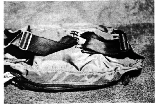
6.5 The Beltpack
For all display head-sets, a beltpack, purchased at a local wilderness outfitters' store, held the video display
receivers, tuners and power [See Figure 29]. The pack is
small, fitting around the waist of the user and buckling like a belt. To hold down the various components stored in the beltpacks, several strips of velcro were added on the
inside of the packs. Cables from the display head-set traveled down the user's back into the beltpack.
6.6 Optics
The selection of the optical system used in the display head-set was difficult because of the hundreds of possible trade-offs and an insufficient knowledge of what to expect. The optics had to fit into a small area and had to be
lightweight. Because of all the variables, the design was kept as simple as possible, using two basic lenses, a
Figure 29. A2 F fb f B A2H" Figure 30. f, fA-A
spherical achromat and a simple magnifier. The spherical achromat lens is, in a sense, a compound lens system [21]. Instead of the lens being separated as in a compound lens,
two lenses have been cemented together (see figure 30].
The spherical achromat was used in an attempt to introduce infinite optics into the Panasonic head-set. The lens used in the Sony display head-set was a simple magnifier of 1.2 magnification for enlarging the image, and seems to work
6.7.0 Configuration
Figure 31.
On the Panasonic head-set, the casings were attached to
both right and left sides of the helmet [See Figure 31].
Located inside the casings are the video displays, a mirror, an achromatic lens, and a beamsplitter. The video display was installed parallel to the viewer's eyes. The mirror was placed in front of the video display at a 45 degree angle to reflect the video image into the achromat lens. The beamsplitter set in front of the achromat reflected the video image another 45 degrees into the viewer's eye [See
Figure 32.
Figures 32,33]. Each plastic casting for the Panasonic displays rested on three brackets bolted onto the Honeywell helmet; one bracket was located in front, the other two
located under the video display [see Figure 28].
For protection of the beamsplitters, a two inch round section of plexiglass was placed on the inside of the
Honywell mask over the eye openings. Light aluminum rings were machined to friction-fit over the plastic casings and the round pellicle beamsplitter (as can be seen in Figures
31 through 33). A piece of plexiglass was cemented onto the ring to protect the beamsplitters from the outside.
The aluminum rings protect the beamsplitters while they act to lock both plastic casings into position.
Because of the Sony video display's unique design, the displays are placed on top of the head-set face down. The video display image passes though a lens and is reflected
at 45 degrees off a beamsplitter into the user's eye [See
Figure 34]. By placing the display face down, the optical
path is shortened, and the area on the left and right side of the head-set can be opened up for increased vision. The head-set using Panasonic video displays severely limits user field of vision. More importantly, the use of the
light-weight solid state displays in a head-set enabling a more compact design.
The casings for the Sony video display consist of two
sections. One section cradles both video displays, side by side, and is located on top of the helmet. The second
section lays on top of and in front of the helmet, and partly covers the CRTs and houses the lenses and the
beamsplitters [See Figure 35]. Both sections are attached
to the helmet by two brackets and velcro. The lenses used in the display are simple magnifiers, and work quite well.
6.7.1 A Final Configuration
In the final configuration (or the third generation), the display head-set using the Sony video displays was modified by cutting away everything below the rim of the helmet [See
Figure 36]. Thus, the beamsplitters and eye piece located below the rim of the helmet were removed from the head-set. Instead, the beamsplitters were attached at 45 degrees to
an eyeglass frame [See Figure 37]. The head-set became two
separate parts, one holding the video displays and the other a pair of glasses housing the beamsplitters. It is now possible to construct small removable beamsplitters that can be added or removed from any pair of glasses. By
Figure 34.
Figure 36.
attaching the beamsplitters directly to the user's normal pair of glasses, the eye piece section of the display head-set is assured to fit and to be comfortable. The approach is one step away from having a very compact
display head-set.
The display head-set using the pair of glasses seems in many ways the best design and implementation. While all head-sets worked, this approach of using glasses
substantially improved the wearability of the head-set (it's just like wearing glasses). Because it is a pair of glasses, the field of vision has been totally opened up
[See Figure 38,39]. Also, the field of vision is not
impaired by either the helmet resting above the user's forehead or the beamsplitters mounted on the glasses. The beamsplitters are unobtrustive because of their relatively
low reflective but high transmission characteristics.
In previous research on head-mounted displays, limited
field of view has been a major problem [46]. Instead of using head-mounted displays for aircraft, head-up systems were developed and used to avoid loss of field of view for pilots. In a way, limited field of vision acts as an
anti-cue associated with the loss of familiarity with the surrounding environment.
Figure 38.
6.8 Head-Set Limitations
One of the most noticeable limitations of the display
head-set is that it is black and white, not color. At this time there are no color displays available in the required size and screen resolution.
The weight of each of the head-sets, about 25 ounces, did not present a problem to the users. However, the comfort of wearing the head-set should be improved, especially if
it is to be worn for an extended period of time. As
display devices become even smaller, it will become easier to design a head-set for comfort.
One of the major problems has been to design a display head-set free of ghost images. Ghost images result from
the reflection of the image off of the uncoated side of the beamsplitter. The first head-set used two five-micron
thick pellicle beamsplitters; because of their thinness,
any ghosting was undetectable by the human eye. However, the pellicle beamsplitters are very delicate and expensive.
For the Sony display head-set, the compromise was to use a one-millimeter thick glass beamsplitter; the thickness and ghosting is hardly noticeable, and requires no cover for
protection.
Ghosting on the Panasonic display head-set is still a
problem because of the plexiglass that is cemented onto the aluminum ring. However, with the success of the thin glass beamsplitters, a permanent solution is to remove the
beamsplitter and replace it with a plexiglass cover on the ring with a custom cut-glass beamsplitter.
Another intermittent and bothersome problem was caused by resoldering several wire leads on PC boards of both Sony and Panasonic video receivers. The soldering was necessary because of the need to extend the CRT's several feet away from the PC boards. However, the leads often shorted out because of normal bending and pulling. In retrospect, the short wires between the CRT and PC board should have been cut and soldered instead, leaving the PC board untouched. Also, the connections on the PC boards should have been cemented with electrical glue for additional strength.
7.0 Implementation of Display Head-Set System
This Chapter examines the implementation of the display head-set as dicussed in Chapter 5. The implementation of a
display head-set system involves a great deal of hardware and software separate from the construction of the head-set, the pre-production of animation stored on the optical
write-once video disc, and the generation of static images. The following is a discussion of this implementation; how it was done, what works, and its limitations. The basic systems involved are shown in the system diagram in Figure 40.
7.1 Transmitting Video To The Display Head-Set
It was assumed from the beginning that for purposes of mobility, the video would be transmitted to the display head-set. The video displays could have been wired up to NTSC, but at a cost of a great deal of time. The benefits
of a slightly better video image did-not seem worth the loss of mobility associated with the additional cables. To receive the transmitted signal, both Sony and Panasonic receivers were kept intact.
32 bit mini-computer Video tion Room Figure 40. once
[7
Oe-R
OR01
transmitter A and B radiator position sensorpurchased [See Figure 41]. The RF modulators accept NTSC
video and transmit it over a range of selectable UHF
channels. The device is normally used by owners of
personal computers who wish to use their home television as a computer monitor. For our purpose the reception was
excellent; receivers placed within 60 feet could easily pick up a transmission. For stereo transmission, two RF
modulators mounted in the Media Room are tuned to separate
UHF channels and are received individually by the two TV
receivers.
7.2 Video Generation
The source of the video images transmitted to the display head-set is the Panasonic Optical Write-Once recorder /
player. As was discussed in Chapter 5, images were
pre-recorded for real-time playback. Until the arrival of a second Panasonic Optical Write-Once recorder, the second group of images needed for stereo came from the
laboratory's EIGEN magnetic video recorder. In concept, the EIGEN magnetic video recorder is very similar to the
optical version, because it records and plays individual static images. However, the EIGEN actually has a read /
write medium, and suffers from limited storage (600 fields of video), and maintains a limited interactive vocabulary.
Since both stereo pairs are stored on the optical
write-once recorder, the images must be down loaded on to the EIGEN recorder. For static images, the laboratory's
frame buffers were used for the video generation.
7.3 Location - Media Room
The Media Room located at the Architecture Machine Group's laboratory has been the sight for much of the testing of the display head-set. The room is about the size of a personal office, but with many more amenities, such as
![Figure 45]. The Glove can simulate the sensation of touching objects and surfaces by controlling tactual](https://thumb-eu.123doks.com/thumbv2/123doknet/13798739.440931/91.918.177.708.456.817/figure-simulate-sensation-touching-objects-surfaces-controlling-tactual.webp)