HAL Id: hal-01313283
https://hal.archives-ouvertes.fr/hal-01313283
Submitted on 9 May 2016
HAL is a multi-disciplinary open access
archive for the deposit and dissemination of
sci-entific research documents, whether they are
pub-lished or not. The documents may come from
teaching and research institutions in France or
abroad, or from public or private research centers.
L’archive ouverte pluridisciplinaire HAL, est
destinée au dépôt et à la diffusion de documents
scientifiques de niveau recherche, publiés ou non,
émanant des établissements d’enseignement et de
recherche français ou étrangers, des laboratoires
publics ou privés.
Simulation of Metal Forming Processes with a 3D
Adaptive Remeshing Procedure
Bessam Zeramdini, Camille Robert, Guénaël Germain, Thomas Pottier
To cite this version:
Bessam Zeramdini, Camille Robert, Guénaël Germain, Thomas Pottier. Simulation of Metal Forming
Processes with a 3D Adaptive Remeshing Procedure. ESAFORM 2016 - 19th International ESAFORM
Conference on Material Forming, Apr 2016, Nantes, France. pp.6, �10.1063/1.4963636�. �hal-01313283�
Simulation of Metal Forming Processes with a 3D Adaptive
Remeshing Procedure
Bessam Zeramdini
1, a), Camille Robert
1, b), Guenael Germain
1, c)and Thomas Pottier
2, d)1
LAMPA, Arts et Métiers ParisTech at Angers
2 Boulevard du Ronceray, BP 93525, F-49035 Angers cedex 01, France 49100 Angers
2Ecole Nationale Supérieure des Mines d’Albi
Mines d’Albi-Carmaux, Campus Jarlard 81013 Albi a) [email protected] b) [email protected] c) [email protected] d) [email protected]
Abstract. In this paper, a fully adaptive 3D numerical methodology based on a tetrahedral element was proposed in order
to improve the finite element simulation of any metal forming process. This automatic methodology was implemented in a computational platform which integrates a finite element solver, 3D mesh generation and a field transfer algorithm. The proposed remeshing method was developed in order to solve problems associated with the severe distortion of elements subject to large deformations, to concentrate the elements where the error is large and to coarsen the mesh where the error is small. This leads to a significant reduction in the computation times while maintaining simulation accuracy. In addition, in order to enhance the contact conditions, this method has been coupled with a specific operator to maintain the initial contact between the workpiece nodes and the rigid tool after each remeshing step. In this paper special attention is paid to the data transfer methods and the necessary adaptive remeshing steps are given. Finally, a numerical example is detailed to demonstrate the efficiency of the approach and to compare the results for the different field transfer strategies.
INTRODUCTION
The numerical simulation of metal forming processes typically involves high strain rates, large inelastic deformations, complex contact conditions with friction and the generation of high temperatures. In addition local and severe distortion of the FE mesh can occur in regions with high gradients in the physical fields (stress/strain/internal variables/temperature…). In this case, the ability to achieve a proper analysis with reasonable CPU cost is limited by the constraint of using a fixed finite element mesh. Indeed the optimal mesh configuration changes continuously throughout the metal forming process. Therefore, successive mesh adaptation is needed during the numerical simulation in order to adaptively control the element size and quality according to the geometrical shape or/and physical solution. Once a new mesh is generated, two approaches are possible: either the simulation is totally recomputed, or all the state variables and history -dependent variables at the end of the previous load step must be transferred from the old mesh to the new one, in order to continue the simulation. In this work the second approach is adopted. This is a delicate issue because if these new field variables are not adequately determined, the simulation accuracy can be severely affected [1].
In the present paper, after a presentation of the shape function approaches for transferring nodal field s, the case where the information is stored at integration points will be detailed. Then, the 3D adaptive remeshing methodology is discussed. Finally, the numerical simulation of metal forming is presented with three data transfer methods.
MAPPING OF VARIABLES
The transferring approach strongly depends on the type of state variable field s which needs to be transferred. At least, when transferring the continuous variables stored at nodal positions (such as displacements, velocity and temperature) the interpolation can be available via the finite element shape function. However, when transferring discontinuous variables (between two elements) stored at integration points (such as stress, strain and internal variables) the transfer is not straight forward.
Method suited to nodal field transfer: Transfer operator P1
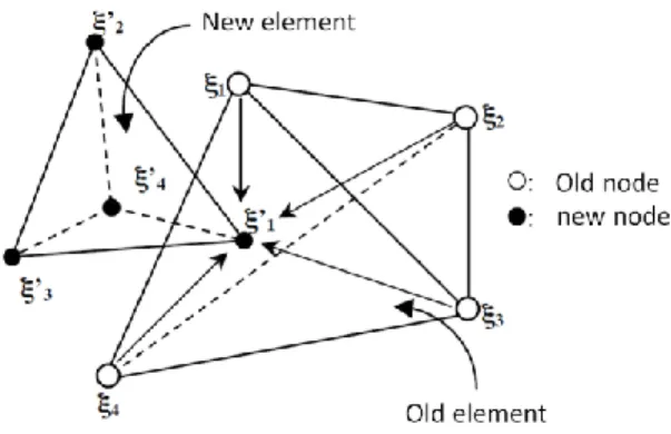
This operator, transfers the values stored at the nodes from the old mesh to the nodes of the new mesh. As shown in figure 1, the overall procedure is split into several steps:
1- Find which element of the old mesh contains a particular node of the new mesh. 2- If case 1 fails, search the nearest element.
3- Search the local coordinates of the new node in the old element.
4- Interpolate (or extrapolate, if case 1 failed) the nodal fields at the new nodal point.
FIGURE 1. The several steps data transfer operators P1
Method suited to element field transfer: Transfer operator P0
A wide range of element data transfer methods between meshes have been reported [1-3]. Basically all these methods can be categorized into two types :
- Direct transfer - Indirect transfer
The oldest method used for direct transfer is “direct projection V1”. The value at an integration point of the new mesh is directly copied from the nearest integration point of the old mesh. This method has the advantage of being applicable to any type of cloud by not having to consider the discretization of the two meshes involved. Moreover, this method will not violate the compatibility of the internal states variables because a similar projection will be applied for all the element fields. Bérard et al. [4] further improved this direct approach “direct projection V2”. They proposed not only to affect the value at the integration point of the final mesh from the nearest initial integration point, but also impose the condition that the two integration points must be geometrically located within the same initial element.
Concerning indirect transfer methods, the procedure for transferring element fields adopted in this work is split into three distinct steps which are summarized in figure 2. First the average values of the internal variables are transferred from the old integration points to the old nodes. Then, as mentioned above, the new nodal values are computed by simple interpolation of the old nodal values using the shape functions of the old mesh. Finally, the state variables at the Gauss point of the new mesh are obtained by employing the shape function of the new elements. The numerical result with these three Methods will be compared, in order to study the compatibility of the state transfer with the initial field and the numerical diffusion solution.
FIGURE 2.A tree-step procedure illustrating the indirect element field transfer
3D ADAPTIVE REMESHING METHODOLOGY
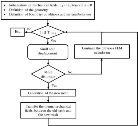
In this work, an algorithm was developed to manage the h-adaptive [5] analysis methodology. A global flowchart of this algorithm is given in figure 3.
Initialization of mechanical fields, t 0 = 0s, iteration n = 0
Definition of the geometry
Definition of boundary conditions and material behavior
Small test displacement
Generation of the new mesh Mesh
distortion
t n ≤Ttotal
End
Transfer the thermomechanical fields between the old mesh and
the new mesh
Continue the previous FEM calculation Yes
Yes
No No
FIGURE 3.Flow chart of the customized FE-simulation for 3D remeshing module
During the first step, an initial mesh based on tetrahedral elements of the struct ure is generated. Then, for each step an ABAQUS/Explicit finite element calculation is performed to numerically simulate the forming process with a small tool displacement. The resulting simulation is analyzed throughout each step. If the number of fully distorted elements does not exceed a given threshold the previous FEM calculation will be continued. Otherwise, if the total number of distorted elements exceeds the threshold, the simulation is cancelled for this loading sequence and a new mesh is then refined and / or coarsened automatically according to the constantly changing physical fields and geometrical shape. If a new mesh is created all field variables are transferred from the old mesh to the new one and the simulation is restarted from the previous FEM calculation.
Interpolation with new mesh shape function Interpolation with old mesh
shape function Extrapolation
Mesh generation
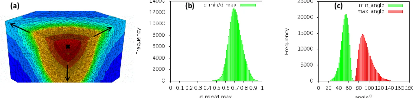
After each small test displacement, the remeshing step is divided into two main steps: the definition of t he new deformed boundary and remeshing of the domain with respect to the geometric size map and the physical s ize map. The geometric size map is defined to reduce the gap between the new mesh geometry and the current boundary discretization. The physical size map is defined to govern the mesh size in the critical areas. A minimal element size hmin is use in the critical areas, and for the others areas an exponential size function is used to increase the element
size, as shown in figure 4 a.
The estimation of the element quality generated by such an adaptive remeshing procedure is critical to the accuracy and validity of the solutions calculated by the finite element method. In this paper, the quality of the mesh is assessed by the following indicators: the dihedral angle and the aspect ratio of the length of the element edges . In this work, an element is classified as being distorted if one of his dihedral angles is larger than 160° or smaller than 10°, or if the second criterion of the element is smaller than 0.2.
(a) (b) (c)
FIGURE 4.M esh size and elements quality : (a) elements size function, (b) aspect ratio of the length of the element edges and (c) dihedral angle
Contact management
At the end of the remeshing step new nodes are created. Sometimes these nodes may artificially penetrate the tool (as show Figure 5).
Surface of the rigid tool
Old Mesh New Mesh
Penetration problem Projected nodes
ModifiedNew Mesh Deformed mesh configuration
FIGURE 5.Schematic representation of the mesh correction for the contact enhancement
Indeed, in numerical simulations of sheet forming operations , the deformation occurs by contact between the workpiece and rigid tools. The workpiece takes the external form of these tools during the deformation steps. However, if one of the new nodes created is located inside the rigid tool, the finite element solution will be erroneous. Therefore, it is necessary to build a relocation procedure. An "r-method" [6] operator is used to project this node outside the tool surface to avoid the interpenetration.
NUMERICAL APLICATION
The three interpolation techniques for the element fields tested here are the “nearest integration point” technique, the “new version of the nearest integration point technique” proposed by Bérard et al. [4] and “the indirect element field transfer” technique. To illustrate the response of these three different techniques, a rigid tool penetrating a
homogeneous workpiece with uniform vertical displacement has been analyzed. According to the symmetry conditions, only one quarter of the workpiece is analyzed as shown in Figure 6.
The element distortion indicators, dihedral angle and the ratio of the length of th e element edges (see figure 4 b and 4 c) are chosen to demonstrate the effective performance of the proposed algorithm after 3 remeshing steps.
FIGURE 6.A metal forming processes: geometry and boundary conditions
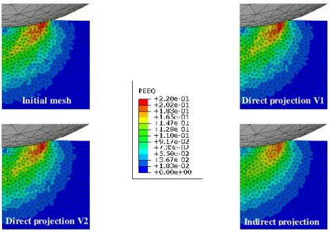
Figure 7 shows the distribution of the total plastic deformation (element variable) using the three different adaptive strategies. In all cases, the same minimum element size is used with hmin=0.002mm. Both the two direct
transfer techniques result in a poor continuous evolution and are in good agreement with the initial distribution while the third transfer method give a good continuous evolution but with smooth diffusion.
FIGURE 7.The distribution of the total plastic deformation using the three different adaptive strategies
The load–displacement curves corresponding to the different adaptive strategies are shown in Figure 8. The results show good correlation of the load–displacement curves for the different strategies. However the results of the adaptive technique compared with the direct transfer procedure shows a small fluctuation in the load -displacement response after each interpolation which can be caused by a small degree of numerical diffusion during the transfer of variables between subsequent meshes. This non -smooth pattern is also observed using various others approaches such as Superconvergent Patch Recovery (SPR) [7] or the unique element method (UEM) [8].
Initial mesh Direct projection V1
FIGURE 8.The load-displacement curves using the different adaptive strategies
CONCLUSION
In the present paper, an adaptive remeshing methodology based on a tetrahedral element was proposed to simulate a wide variety of 3D forming processes. This methodology is implemented step by step in order to adapt automatically to the constantly changing geometrical shapes and physical fields. The load-displacement curves using the different adaptive strategies show that the indirect transfer strategy can significantly reduce the fluctuation after each remeshing step. The proposed approach was validated by the numerical analysis of the metal forming process and is shown to be efficient. In further works, a Zienkiewicz-Zhu type error estimator [9] will be use in order to adaptively control the element size and optimize the finite mesh according to the physical solution.
REFERENCES
1. D. Dureisseix and H. Bavestrello, Information transfer between incompatible finite element meshes: Application to coupled thermo-viscoelasticity, Computer Methods in Applied Mechanics and Engineering. 85, 6523-6541 (2006).
2. S. Kumar, L. Fourment and S. Guerdoux, Parallel, second-order and consistent remeshing transfer operators for evolving meshes with superconvergence property on surface and volume, Finite Elements in Analysis and Design. 93, 70-84 (2015).
3. O.C. Zienkiewicz and J.Z. Zhu, The superconvergent patch recovery (SPR) and adaptive finite element refinement, Comput. Methods Appl. Mechan. Eng. 101, 207–224 (1992).
4. A. Bérard, P. Hild, V. Cano and S. Meunier, Transfert de champs entre maillages de type éléments finis et applications numériques en mécanique non linéaire des structures, 10e Colloque National en Calcul des Structures (2011).
5. P. Díez, and A. Huerta, A unified approach to remeshing strategies for finite element h adaptivity. Computer Methods in Applied Mechanics and Engineering. 176, 215–229 (1999).
6. A. Tezuka and O. Okuda, Trial by the r-method - An adaptive mesh refinement for the finite-element method. JSME International Journal - Series I, 31(1), 50 (1988).
7. A.R. Khoei, S.A. Gharehbaghi, A.R. Tabarraie and A. Riahi, Error estimation, adaptivity and data transfer in enriched plasticity continua to analysis of shear band localization, Applied Mathematical Modelling. 31, 983-1000 (2007).
8. Y. Hu and M.F. Randolph, H-adaptive FE analysis of elasto-plastic non-homogeneous soil with large deformation, Computers and Geotechnics. 23, 61-83 (1998).
9. O.C. Zienkiewicz and J.Z. Zhu, A simple error estimator and adaptive procedure for practical engineering analysis, Int. J. Numer. Methods Eng. 24, 337–357 (1987).