HAL Id: hal-01421335
https://hal.archives-ouvertes.fr/hal-01421335
Submitted on 28 Dec 2016
HAL is a multi-disciplinary open access
archive for the deposit and dissemination of
sci-entific research documents, whether they are
pub-lished or not. The documents may come from
teaching and research institutions in France or
abroad, or from public or private research centers.
L’archive ouverte pluridisciplinaire HAL, est
destinée au dépôt et à la diffusion de documents
scientifiques de niveau recherche, publiés ou non,
émanant des établissements d’enseignement et de
recherche français ou étrangers, des laboratoires
publics ou privés.
A compact circularly-polarized array based on
superdirective elements
Abdullah Haskou, Ala Sharaiha, Sylvain Collardey
To cite this version:
Abdullah Haskou, Ala Sharaiha, Sylvain Collardey. A compact circularly-polarized array based on
superdirective elements. IEEE Middle East Conference on Antennas and Propagation (MECAP), Sep
2016, Beirut, Lebanon. pp.1 - 3, �10.1109/MECAP.2016.7790082�. �hal-01421335�
A Compact Circularly-Polarized Array Based on
Superdirective Elements
Abdullah Haskou, Ala Sharaiha and Sylvain Collardey
IETR UMR CNRS 6164- Université de Rennes 1, Rennes, France
Corresponding author email: [email protected]
Abstract—In this paper, a new strategy for designing compact
Circularly-Polarized (CP) arrays is proposed. This approach consists of using small parasitic superdirective arrays as unit elements. An array is designed for 866M Hz RFID band and a parametric analysis on the inter-element distance is performed to highlight the trade-offs between the antenna- dimensions, -directivity and radiation efficiency. For total dimensions of
220× 220 × 25.8mm3(0.58λ× 0.58λ × 0.075λ), the array has
a CP directivity of 10.3dBic and a radiation efficiency of 38.5%.
Keywords—Superdirective arrays, parasitic elements, circular polarization.
I. INTRODUCTION
Novel wireless technologies require increasingly compact antennas. However, conventional arrays lead to a significant increase in their size. Meanwhile, in superdirective arrays the unit-elements are put very closely together and their excitation coefficients are controlled to achieve the maximum directivity (in the end-fire direction) predicted by Uzkov [1]. Recently, there has been a renewed interest in superdirective arrays and in particular electrically small ones [2]-[11]. In this paper, we propose a new strategy for designing compact Circularly-Polarized (CP) arrays by using small superdirective arrays as unit-elements. The constraints including the maximum directivity, the efficiency, the antenna dimensions are studied. Results are validated through the realization and measurement of a 2× 2 array.1
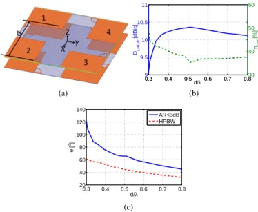
II. ARRAYGEOMETRY ANDPARAMETRICSTUDY
In [10] a design methodology for superdirective arrays was detailed. It was shown that, by exciting one element and loading the others, the same excitation coefficients, and hence the same directivity radiation pattern, as in the fully driven array can be achieved. This method was used in [11] to design a two-element array for 866M Hz RFID band. The unit-element used in the array is a short-circuited half loop antenna [8]. In the array, one element was excited while the other was loaded with a capacitor of 3.3pF . The antenna had a size factor of ka = 1.1 and it had a simulated (HFSS [12]) total ditrectivity of 7dBi and radiation efficiency of 43.4%. Four elements of this array are integrated in 2× 2 planar CP array (using the classical sequential rotation method) as shown in Fig. 1(a). The four elements are excited with phases of 0, 90o, 180o and 270o to achieve a Left-Hand
1This work was done with the funding of the French National Research
Agency as part of the project "SOCRATE" and the support of the "Images et Reseaux" cluster of Brittany region, France.
Circular-Polarization (LHCP). It should be noticed that these excitations can be reversed to achieve Right-Hand Circular-Polarization (RHCP). The spacing between the elements d (calculated as a straight line between the excitation ports as shown in Fig. 1(a)) is changed from 10.1cm to 27.6cm. Fig. 1(b) shows the antenna maximum LHCP directivity and the efficiency as a function of the distance. It can be noticed that as the distance increases the coupling effect decreases and the achieved directivity increases till it reaches its maximum value around 0.5λ where it starts decreasing again. We can also note that as the distance increases the radiation efficiency decreases and it reaches its minimum when the maximum directivity occurs. Fig. 1(c) shows the antenna Half Power BeamWidth (HPBW) and CP aperture for an Axial Ratio (AR) < 3dB. As it can be noticed, CP aperture is always higher than the the HPBW. Moreover, AR is lower than 1dB in the entire HPBW.
(a) 0.3 0.4 0.5 0.6 0.7 0.8 9 9.5 10 10.5 11 DLHCP [dBic] d/λ 0.3 0.4 0.5 0.6 0.7 0.830 40 50 60 ηrad [%] (b) 0.3 0.4 0.5 0.6 0.7 0.8 20 40 60 80 100 120 140 θ [ o] d/λ AR<3dB HPBW (c)
Fig. 1. Planar CP array simulated parameters as a function of the separation. (a) Geometry, (b) LHCP directivity and radiation efficiency and (c) HPBW and CP aperture.
III. SIMULATION ANDEXPERIMENTALRESULTS
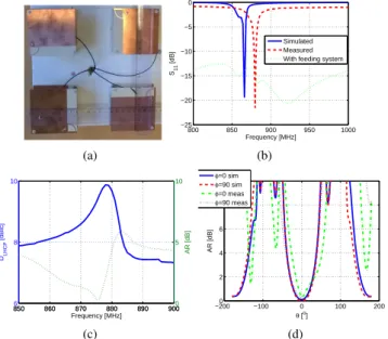
A prototype of the antenna was fabricated and measured for a distance of 15.6cm ≈ 0.45λ (Fig. 2(a)). Two ZX10-2-20+ power dividers (0, 180o) [13], a hybrid coupler (0, 90o) from KDI/triangle [14], and four 30cm-long UFL cables [15] are used for the feeding system. Fig. 2(b) shows the antenna input reflection coefficient magnitude in dB. The antenna has a
simulated/measured resonance frequency of 866/879.8M Hz (a frequency shift of 1.6%). The antenna with the feeding system is well matched in all the observed band. This is mainly due to the losses in the feeding system. The antenna measured LHCP directivity given in Fig. 2(c) shows it increases till it reaches its maximum value of 10dBic at the resonance frequency then it starts decreasing again. The measured AR is also minimal around the resonance frequency. The antenna has a measured CP bandwidth (AR < 3dB) of 21M Hz. Fig. 3(a) shows the antenna 3D LHCP directivity radiation pattern. It can be observed that the measured result is in a good agreement with the simulated one. The antenna has a simulated/ measured directivity of 10.3/10dBic in broadside direction (oZ). The antenna cross-polar (RHCP) 3D directivity radiation pattern is given in Fig. 3(b). The measured result is in acceptable agreement with the simulated one. The antenna 2D main- and cross-polar -directivity radiation patterns are given in Fig. 4. It can be noticed that the measured results in the main-polar are in a good agreement with the simulated ones. The simulated/ measured HPBW in E (XoZ) and H (YoZ) planes are respectively 48/45o and 40.3/50.6o and FBR is 40.3/19.8dB. The small difference in the cross-polar levels is mainly due to the measurement environment (the feeding system and the support). The antenna has a simulated radiation efficiency of 38.5% and reveals a measured one of about 40% after compensating the losses in the feeding system.
(a) 800 850 900 950 1000 −25 −20 −15 −10 −5 0 Frequency [MHz] S11 [dB] Simulated Measured With feeding system
(b) 8506 860 870 880 890 900 8 10 DLHCP [dBic] Frequency [MHz] 850 860 870 880 890 9000 5 10 AR [dB] (c) −2000 −100 0 100 200 2 4 6 8 10 θ [o ] AR [dB] φ=0 sim φ=90 sim φ=0 meas φ=90 meas (d)
Fig. 2. Planar CP array with d = 15.6cm. (a) Fabricated prototype, (c) input reflection coefficient magnitude in dB, (d) measured LHCP directivity and AR as a function of the frequency and (e) AR.
IV. CONCLUSION
In this paper, a new design approach for compact CP arrays was presented. This approach consisted of using small parasitic superdirective arrays as unit elements. An array of total dimensions of 0.58λ× 0.58λ × 0.075λ having a LHCP directivity of 10.3dBic and a radiation efficiency of 38.5% was designed for RFID applications. The experimental results were in a good agreement with the simulated ones.
(Simulated) (Measured)
(a)
(Simulated) (Measured)
(b)
Fig. 3. Planar CP array 3D directivity radiation pattern for d=15.6cm. (a) Co-polar and (b) cross-polar.
−25 −15 −5 5 15 30 210 60 240 90 270 120 300 150 330 180 0 θ [°] Directivity [dBic] LHCP Simulated LHCP Measured RHCP Simulated RHCP Measured (a) −25 −15 −5 5 15 30 210 60 240 90 270 120 300 150 330 180 0 θ [°] Directivity [dBic] LHCP Simulated LHCP Measured RHCP Simulated RHCP Measured (b)
Fig. 4. Planar CP array 2D LHCP and RHCP directivity radiation pattern for d=15.6cm. (a) E plane and (b) H plane.
REFERENCES
[1] I. Uzkov, "An Approach to the Problem of Optimum Directive Antennae
Design", Comptes rendues (Doklady) de l’académie des sciences de
l’URSS, vol. 53, no. 1, 1946.
[2] E. E. Altshuler, T. H. O’Donnell, A.D. Yaghjian, and S. R. Best, "A
Monopole Superdirective Array", IEEE Transactions on Antennas and
Propagation, vol. 53, no. 8, pp. 2653-2661, August 2005.
[3] T. H. O’Donnell, and A. D. Yaghjian, "Electrically Small Superdirective
Arrays Using Parasitic Elements", IEEE Antennas and Propagation
Society International Symposium 2006, pp. 3111,3114, 9-14 July 2006. [4] S. Lim, and H. Ling, "Design of Electrically Small Yagi Antenna",
Electronics Letters, vol. 43, no. 5, pp. 3-4, 1 March 2007.
[5] A. D. Yaghjian, T. H. O’Donnell, E. E. Altshuler, and S. R. Best
"Electrically Small Supergain End-Fire Arrays", Radio Science, vol. 43,
2008.
[6] P. Sharma, D. Arora, and H. Gupta, "Designing Superdirective Patch
An-tenna Array Using Metamaterial", International Journal of Engineering
Research & Technology (IJERT), vol. 1, issue 8, October 2012. [7] O. S. Kim, S. Pivnenko, and O. Breinbjerg, "Superdirective Magnetic
Dipole Array as a First-Order Probe for Spherical Near-Field An-tenna Measurements", IEEE Transactions on AnAn-tennas and Propagation,
vol. 60, no. 10, pp. 4670-4676, October 2012.
[8] B. Sentucq, A. Sharaiha, and S. Collardey, "Superdirective
Metamaterial-Inspired Electrically Small Antenna Arrays", 7th European Conference
on Antennas and Propagation (EuCAP 2013), pp.151,155, 8-12 April 2013.
[9] A. Clemente, M. Pigeon, L. Rudant, and C. Delaveaud, "Design of a
Super Directive Four-Element Compact Antenna Array Using Spherical Wave Expansion, IEEE Transactions on Antennas and Propagation,
vol. 63, no. 11, pp. 4715-4722, November 2015.
[10] A. Haskou, A. Sharaiha, and S. Collardey, "Design of Small Parasitic
Antennas and Propagation, vol. 63, no. 12, pp. 5456-5464, December 2015.
[11] A. Haskou, A. Sharaiha, and S. Collardey, "Compact Planar Arrays Based on Parasitic Superdirective Elements", 10th European Conference on Antennas and Propagation (EuCAP 2016), Davos, Switzerland, 10-15 April 2016.
[12] ANSYS HFSS, Pittsburg, PA 15219, USA.
[13] [Online]. Available: www.minicircuits.com/pdfs/ZX10-2-20.pdf [14] [Online]. Available: http://www.datasheetarchive.com/dl/Scans-060/
DSA2IH0075492.pdf
[15] [Online]. Available: http://docs-europe.electrocomponents.com/ webdocs/12a7/0900766b812a766a.pdf