Desenvolvimento de nanocatalisadores suportados em
nanocompósitos magnéticos contendo sílica, céria e
titânia
Design of nanocatalysts supported on magnetic
nanocomposites containing silica, ceria and titania
Tese apresentada ao Instituto de Química da Universidade de São Paulo e à Université Toulouse III – Paul Sabatier para obtenção do título de Doutor em Ciências (Química)
Orientadora: Profª Dar. Liane Marcia Rossi Coorientadora: Drª Karine Philippot
São Paulo
2015
For Natália You are the light of my life
For my mother and my uncle You are not here, but you will always be with us
To Prof. Dr. Liane M Rossi for her long time support and supervision of this thesis. To Dr. Karine Philippot for all the support during my time in Toulouse and the co-supervision of this thesis.
To Prof. Dr. Jivaldo R. Matos for thermal analysis, Prof. Dr. Alcindo A. Dos Santos for gas chromatography, Prof. Dr. Renato F. Jardim for magnetic measurements, Prof. Dr. Marcia C. A. Fantini for X-ray Diffraction, Prof. Dr. Pedro K. Kiyohara for Transmission electron microscopy, Prof. Dr. Richard Landers for X-ray photoelectron spectroscopy and Prof Dr Renato F. Jardim for SQUID measurements.
To my wife who is the reason for finishing this text
To my aunt that provided a comfortable place to write and awesome food To the colleagues in Brazil and in France that helped me in the lab
To the Brazilian Nanotechnology National Laboratory (LNNano) for the Transmission electron microscopy facilities (JEOL JEM 2100).
To the Brazilians agencies that gave financial support the Fundação de Amparo à Pesquisa do Estado de São Paulo (FAPESP), that provided a PhD fellowship in Brazil, and the Coordenação de Aperfeiçoamento de Pessoal de Nível Superior (CAPES), that provided a PhD fellowship connected to the CAPES-COFECUB (Comité Français d’Évaluation de la Coopération Universitaire et Scientifique avec le Brésil) project 695/10 during the time in France.
Je vois la vie en rose
La Vie en Rose Edith Piath
Vono, L.L.R. DESENVOLVIMENTO DE NANOCATALISADORES SUPORTADOS EM NANOCOMPÓSITOS MAGNÉTICOS CONTENDO SÍLICA, CÉRIA E TITÂNIA. 2016. (205p). Tese de Doutorado – Programa de Pós-Graduação em Química. Instituto de Química, Universidade de São Paulo, São Paulo, Brasil e Université Toulouse III – Paul Sabatier, Toulouse, França.
A separação magnética tem recebido muita atenção como uma tecnologia robusta, altamente eficiente e rápida para recuperar catalisadores sólidos após uso em reações em fase líquida. Muitos estudos têm focado nas metodologias para a imobilização de espécies cataliticamente ativas, mas o desenvolvimento de suportes magnéticos tem se limitado a nanopartículas magnéticas revestidas com sílica, polímeros ou carbono. O desenvolvimento de nanocompósitos magnéticos com a incorporação de outros óxidos é muito desejável para ampliar a aplicação dessa tecnologia de separação em catálise. Nesse contexto, estudos da estabilidade térmica de magnetita revestida com sílica (Fe3O4@SiO2) foram realizados para
avaliar a possibilidade de calcina-la sem perder as propriedades magnéticas do suporte. Uma etapa de calcinação é necessária para a deposição de diferentes óxidos na superfície da sílica, tais como céria e titânia. O Fe3O4@SiO2 calcinado preservou a morfologia “core-shell” e as
propriedades magnéticas, porém apresentou um aumentou de seis vezes na área superficial. Novos suportes magnéticos foram desenvolvidos pela deposição de céria e titânia sobre magnetita previamente revestida com sílica. Nanocatalisadores magneticamente recuperáveis de Rh, Pd e Ru foram preparados. Os catalisadores foram utilizados na hidrogenação de ciclo-hexano, benzeno ou fenol e o principal objetivo dessa tese foi o estudo da influência de cada suporte na atividade catalítica. Os catalisadores foram preparados de duas formas diferentes: impregnação-redução e imobilização de nanopartículas (NPs) metálicas pré-formadas. As NPs coloidais foram preparadas pela redução de sais metálicos e, também, pela decomposição de complexos organometálicos. Catalisadores de ródio preparados pela impregnação de cloreto de ródio(III) e redução com H2 mostraram alguns problemas de reprodutibilidade, que foram
superados utilizando NaBH4 ou hidrazina como agentes redutores. A preparação de
catalisadores pela imobilização de NPs coloidais é uma alternativa interessante para obter catalisadores reprodutíveis e muito ativos. Nanopartículas de Pd, Rh e Ru foram preparadas a partir de organometálicos e imobilizadas em Fe3O4@SiO2 calcinada, Fe3O4@SiO2CeO2 e
Fe3O4@SiO2TiO2. A eliminação do agente estabilizante torna os catalisadores mais ativos
durante os reusos. O catalisador de Rh sobre o suporte de céria foi o catalisador mais ativo na hidrogenação de ciclohexeno (TOF 125000 h-1). O catalisador de Pd foi o catalisador mais seletivo para a hidrogenação de fenol em ciclo-hexanona, independente do suporte usado. A formação de ciclo-hexanol é favorecida pelo suporte de titânia e a hidrodesoxigenação para produzir ciclo-hexano ocorreu principalmente no suporte de sílica.
Palavras-chave: Catálise, suporte magnético, nanopartículas, sílica, céria, titânia, hidrogenação, paládio, ródio, rutênio e ouro.
Vono, L.L.R. DESIGN OF NANOCATALYSTS SUPPORTED ON MAGNETIC NANOCOMPOSITES CONTAINING SILICA, CERIA AND TITANIA. 2016. (205p) PhD Thesis – Graduate program in Chemistry. Instituto de Química, Universidade de São Paulo, São Paulo, Brazil and Université Toulouse III – Paul Sabatier, Toulouse, France.
Magnetic separation has received a lot of attention as a robust, highly efficient and rapid catalyst separation technology. Many studies have focused on developing methodologies for the immobilization of catalytic active species, but the development of magnetic supports has been mainly limited to silica, polymer or carbon-coated magnetic nanoparticles (NPs). The design of magnetic nanocomposites and the incorporation of other oxides are highly welcome to broaden the application of this separation technology in the field of catalysis. In this context, studies of the thermal stability of silica-coated magnetite (Fe3O4@SiO2) were performed to evaluate the possibility of calcining it without losing the
magnetic properties of the support. The calcination would permit the deposition of different oxides on the silica surface, such as ceria and titania. The calcined Fe3O4@SiO2 material
preserved the core-shell morphology and magnetic properties, but increased its surface area six times. New magnetic supports were developed by using post-coating process for the deposition of ceria and titania onto silica-coated magnetite. Magnetically recoverable Rh, Pd and Ru nanocatalysts were prepared. The catalysts were employed in hydrogenation of cyclohexene, benzene or phenol and the study of the influence of each support on the catalytic activity was a main objective of this thesis. The catalysts were prepared by two different approaches: the impregnation and the sol-immobilization of pre-formed metal NPs. The colloidal metal NPs were prepared by reduction of metal salts and also by decomposition of organometallic complexes. Rhodium catalysts prepared by impregnation of rhodium(III) chloride and reduction with H2 showed some reproducibility issues that were surpassed by
using NaBH4 or hydrazine as reducing agents. The preparation of catalysts by the
immobilization of colloidal NPs is an interesting alternative to obtain reproducible and very active catalysts. Nanoparticles of Pd, Rh and Ru were prepared by an organometallic approach and immobilized on calcined Fe3O4@SiO2, Fe3O4@SiO2CeO2 and
Fe3O4@SiO2TiO2. The elimination of the stabilizing agent leads to more active catalysts upon
recycling. Rhodium catalysts supported on ceria support was the most active catalyst in the hydrogenation of cyclohexene (TOF 125,000 h-1). Palladium catalysts were the most selective catalyst for the hydrogenation of phenol to cyclohexanone, no matter the support used. The formation of cyclohexanol is enhanced with titania and the hydrodeoxygenation to produce cyclohexane occurred mainly with silica.
Keywords: Catalysis, magnetic support, nanoparticles, silica, ceria, titania, hydrogenation, palladium, rhodium, ruthenium and gold.
Vono, L.L.R. ELABORATION DE CATALYSEURS SUPPORTES PAR DEPOT DE
NANOPARTICULES METALLIQUES SUR DES COMPOSITES MAGNETIQUES
CONTENANT DE LA SILICE, DE L'OXYDE DE CERIUM ET DE L'OXYDE DE TITANE. 2016. (205p) Thèse de doctorat – Programme d'études supérieures en chimie. Instituto de Química, Universidade de São Paulo, São Paulo, Brésil et Université Toulouse III – Paul Sabatier, Toulouse, France.
Introduction
L'une des principales différences entre les catalyseurs homogènes et hétérogènes est la séparation du catalyseur des produits de réaction. En général, les catalyseurs hétérogènes sont assez facilement séparés, mais cela peut s’avérer parfois difficile en fonction de la granulométrie et de la densité du support de catalyseur et nécessiter le recours à des méthodes telles que filtration et centrifugation. De ce fait, la séparation magnétique a reçu beaucoup d'attention, offrant une technologie de séparation aisée, rapide et efficace du catalyseur solide. Par ailleurs, la séparation magnétique du catalyseur peut être effectuée sans le retirer du réacteur, évitant ainsi la perte de masse et l'oxydation due à l'exposition à l'air. La caractéristique essentielle pour un bon support magnétique est la propriété de superparamagnétisme. Le superparamagnétisme se caractérise par une aimantation à saturation élevée lors de l’application d‘un champ magnétique et l'absence de magnétisation résiduelle lorsque le champ magnétique n’est plus appliqué. Des matériaux magnétiques massifs présentent une structure de multidomaines, mais lorsqu’ils sont préparés de façon à obtenir une taille de grains en dessous d'un diamètre critique, la formation d’un domaine unique est énergétiquement favorable. La magnétite (Fe3O4) est un matériau magnétique
atteindre cette caractéristique. De nombreuses études ont été focalisées sur l'immobilisation d'espèces actives catalytiques, mais le développement de supports magnétiques est souvent limité à des nanoparticules enrobées par du carbone, un polymère ou une silice. Par conséquent, l’élaboration de nanocomposites magnétiques incorporant d'autres oxydes que la silice apparait comme une voie intéressante pour élargir l'application de la technologie de séparation magnétique dans le domaine de la catalyse.
Préparation de supports magnétiques
Préparation et comportement thermique de particules de magnétite recouvertes de silice
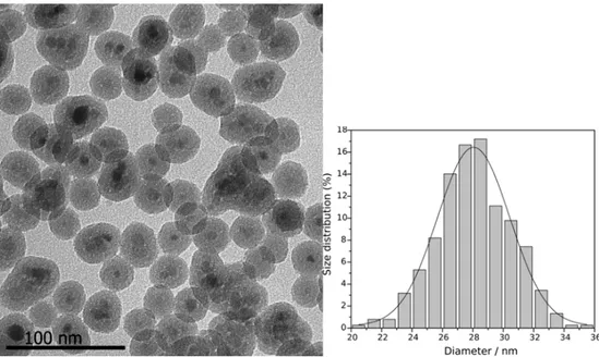
Un nanocomposite constitué de particules de magnétite recouvertes de silice (Fe3O4@SiO2) a été préparé par la méthode de micro-émulsion inverse, conduisant à des
matériaux de haute qualité. L'influence de la durée de la réaction a été évaluée en prélevant des échantillons à différents temps de réaction typiquement: 1, 2, 6, 12, 24 et 48 h (figure 1a). Le matériau préparé en 6 h présente une taille de particules de 28,0 ± 2,0 nm (figure 1b).
micrographie obtenue par MET.
Le comportement thermique a été évalué par thermogravimétrie (TG) et la calorimétrie à balayage différentiel (DSC). L’analyse par thermogravimétrie a montré que le résidu organique présent dans l’écorce de silice est principalement composé de tensioactif qui demeure après lavage (figure 2a). L’analyse par DSC a indiqué que l'écorce de silice protège les noyaux de magnétite contre l'oxydation (figure 2b). Après calcination sous air à 500 ° C pendant 2 h le matériau obtenu (Fe3O4@SiO2Cal) a montré une morphologie et une taille de
particules core-shell préservées. (figure 3) Les solides Fe3O4@SiO2 et Fe3O4@SiO2Cal ont été
caractérisés par diffraction des rayons X sur poudres et la comparaison des pics de diffraction de la magnétite montre qu’elle a été préservée.
Figure 2. (a) TG (ligne solide) et DTG (ligne pointillés) obtenu avec l’énchantilion Fe3O4@SiO2 sous l’air (noir)
et azote (rouge). (b) DSC obtenues pour la magnétite pure (rouge) et de magnétite revêtues d'oxyde de silicium (noir).
Figure 3. Micrographie obtenue par MET d’échantilion Fe3O4@SiO2 aprés calcination.
Les mesures magnétiques ont montré que les deux matériaux sont superparamagnétiques et que l’aimantation à saturation est réduite à 13% après calcination (figure 4). La calcination a permis d’augmenter de 6 fois la surface spécifique. Ainsi, la calcination devrait permettre le dépôt de différents oxydes sur la surface de la silice, tels que l'oxyde de cérium et l'oxyde de titane.
-0 100 200 300 400 500 600 700 800 900 Temp [C] 84 86 88 90 92 94 96 -6.191 % -9.002 % 449.21C -8.964% 390.69C 100.00 200.00 300.00 400.00 500.00 Temp [C] -0.00
Post-revêtement avec d’oxyde de cérium ou d’oxyde de titane
Un processus de post-revêtement a été développé pour le dépôt d'oxyde de cérium et d'oxyde de titane sur Fe3O4@SiO2. Malgré plusieurs tentatives, le dépôt de TiO2 à la surface
de Fe3O4@SiO2 n’a pas pu être réalisé. Le dépôt de TiO2 sur Fe3O4@SiO2 a donc été effectué
par modification d'une méthode décrite pour la préparation de composites « jaune d’œuf » conduisant au matériau Fe3O4@SiO2TiO2. Pour le dépôt de CeO2 le solide Fe3O4@SiO2 a été
traité avec une solution de cérium (IV) et le sel solide a ensuite été séché pour obtenir Fe3O4@SiO2CeO2. Les solides Fe3O4@SiO2TiO2 et Fe3O4@SiO2CeO2 ainsi obtenus ont été
calcinés sous air à 500 °C pendant 2 h. La caractérisation par microscopie électronique en transmission (MET) de l'échantillon Fe3O4@SiO2TiO2 (figure 5a) a montré que la
morphologie cœur-coquille a été préservée et que le dépôt de TiO2 a eu lieu principalement
sous la forme de nanoparticules d’environ 5 nm. Le diffractogramme DRX enregistré pour Fe3O4@SiO2TiO2 n’a révélé que les pics de la magnétite, malgré la présence d’environ 8% en
Figure 5. Micrographie de Fe3O4@SiO2TiO2 obtenu par (a) MET et (b) MEHR.
L’analyse MET de Fe3O4@SiO2CeO2 a montré le dépôt de nanoparticules de CeO2 de
2,6 ± 0,4 nm à la surface du matériau initial (figure 6). Le diffractogramme DRX de Fe3O4@SiO2CeO2 a révélé la présence de pics correspondant à la magnétite d’une part et à
l'oxyde de cérium (phase cubique) d’autre part. Sur les deux diffractogrammes un large pic lié à la silice amorphe est observé.
Les solides Fe3O4@SiO2, Fe3O4@SiO2TiO2 et Fe3O4@SiO2CeO2 ont aussi été
caractérisés par spectroscopie de photoélectrons X-ray. Les spectres XPS de tous les échantillons ont révélé la présence de pics de photoélectrons correspondant à C 1s, O 1s et Si 2p. Les pics de photoélectrons pour Ti 2p ont montré les composantes Ti4+ et Ti3+ mais augmentées de 0,7 eV, par rapport au TiO2 massif. Les pics du Ce ont montré une
augmentation de 2,1 eV, par rapport au CeO2 massif. Le pic de photoélectrons O 1s montre
deux composantes attribuées à SiO2 massif et à des groupes Si-OH de surface. Par ailleurs, le
dépôt d'oxyde de cérium et d'oxyde de titane augmente l’intensité de cette composante, ce qui peut être attribué à O résultant de CeO2 et TiO2.
Catalyseurs de rhodium préparé avec trichlorure de rhodium (III)
Des nanocatalyseurs de rhodium (Rh) supportés ont été préparés par imprégnation d’un support Fe3O4@SiO2 préalablement fonctionnalisé par des groupements amines
(Fe3O4@SiO2NH2) avec une solution de trichlorure de rhodium(III). La réduction du Rh(III)
en Rh(0) a été réalisée en utilisant le dihydrogène H2, le borohydrure de sodium NaBH4 ou
l’hydrazine N2H4. Les catalyseurs préparés par réduction sous H2 n’ont montré pas une bonne
reproductibilité. La réduction par NaBH4 a permis la préparation d'un catalyseur très actif
dans l'hydrogénation du cyclohexène. Toutefois, il a été observé que l'activité de ce catalyseur est dépendante de la charge en métal (tableur 1), alors que les images MET ont révélé des nanoparticules de rhodium de tailles similaires. Les nanoparticules de Rh obtenues en utilisant l’hydrazine comme agent réducteur ont montré une taille de nanoparticules très proche de celle observée pour le catalyseur préparé avec NaBH4. Cependant une différence majeure a
été observée en ce qui concerne la dispersion des nanoparticules sur le support qui s’est avérée bien meilleure dans le cas du catalyseur préparé avec NaBH4. L'activité catalytique en
hydrogénation du cyclohexène obtenue pour le catalyseur préparé avec N2H4 (TOF = 48,700
h-1) s’est révélée inférieure à celle du catalyseur issu de la réduction par NaBH4. Par contre, le
contraire a été observé pour l'hydrogénation du benzène: l'activité catalytique pour le catalyseur préparé par N2H4 (TOF = 1600 h-1) est supérieure à celle déterminée pour le
(nm) (h) 1 0,1 2,8 ± 0,5 0,57 153190 2 0,5 2,2 ± 0,4 0,65 85440 3 1,0 3,1 ± 0,5 0,58 133300 4 1,5 2,8 ± 0,7 0,87 65469 a
Cyclohexène (14,6 mmol), catalyseur (0,4 mol de Rh), substrat/catalyseur = 35600, 75 ºC, 6 bar H2. b Le
temps de conversion complète (> 99 % conversion déterminé par CG). c Turnover frequency défini par mole de substrat consommé x mole de catalyseur introduit x temps de réaction (h) (obtenu à partir de la pente de la
courbe d'hydrogénation dans la conversion < 20 %).
Un autre aspect de ce travail de thèse a consisté en la préparation de nanoparticules de rhodium stabilisées par le polyvinylalcool (PVA) pour obtenir des suspensions colloïdales de rhodium (Rh@PVA) (figure 7a). Pour ce faire, le trichlorure de rhodium(III) a été réduit par NaBH4 en présence de PVA. La suspension colloïdale Rh@PVA ainsi obtenue s’est montrée
très active pour l'hydrogénation du cyclohexène dans des conditions de catalyse biphasique, mais elle s’est avérée instable au cours du temps, la formation d’un précipité ayant été observée après la réaction. Les résultats de l’hydrogenation ont montré que la réaction était limitée par le transfert de masse. L'immobilisation de cette suspension colloïdale par imprégation sur le support Fe3O4@SiO2NH2 (figure 7b) a conduit à une meilleure stabilité du
catalyseur et a permis plusieurs recyclages successifs pendant lesquels une augmentation drastique de l’activité catalytique a été observée.
Catalyseurs de palladium préparé avec disodium tetrachloropalladate(II)
Des catalyseurs de palladium (Pd) supportés ont été préparés par imprégnation de différents supports (Fe3O4@SiO2, Fe3O4@SiO2NH2, Fe3O4@SiO2CalNH2 et Fe3O4@SiO2Cal)
avec une solution de disodium tetrachloropalladate(II) suivie d’une étape de réduction par H2.
Les supports se sont avérés capables d'adsorber des ions Pd2+ sauf le support Fe3O4@SiO2Cal.
Le support sans fonctionnalisation ultérieure a montré une activité supérieure en hydrogénation du cyclohexène, mais au 5ème cycle catalytique, l'activité catalytique a été réduite à 63% de la valeur initiale (figure 8). Les catalyseurs obtenus avec les supports fonctionnalisés ont montré une activité catalytique similaire, mais l'activité de Fe3O4@SiO2NH2Pd était plus constante. Cela pourrait être dû à la faible quantité de
groupements amines sur ce support comparativement au système Fe3O4@SiO2CalNH2. Pour
comparaison, des nanoparticules de Pd stabilisées par la polyvinylpyrrolidone (PVP) ont été préparées en chauffant au reflux une solution aqueuse de Na2PdCl4 en présence de PVP et
Fe3O4@SiO2CalNH2 comme support pour le Pd a été observée inférieure de 22% par rapport
à celle du catalyseur préparé avec Fe3O4@SiO2NH2.
Figure 8. L’activité du Fe3O4@SiO2Pd (gris clair), Fe3O4@SiO2NH2Pd (gris) et Fe3O4@SiO2CalNH2Pd (gris
foncé) dans l’hydrogénation du cyclohexène. Les conditions de réaction: 75 ºC, 6 bar H2 et TON 10000.
Il résulte des résultats obtenus avec les catalyseurs préparés à partir de Fe3O4@SiO2
que la préparation par imprégnation n’est pas triviale et que les caractéristiques du support peuvent avoir une forte influence sur l'activité du catalyseur.
La préparation de nanoparticules métalliques à partir de précurseurs organométalliques est un procédé très prometteur du fait de l’obtention de surfaces métalliques très propres mis à part la coordination du ligand introduit comme stabilisant. Des suspensions colloïdales de Rh, Pd et Ru ont été stabilisées par la PVP. Elles ont été préparées en utilisant des précurseurs organométalliques Rh(C3H5)3, Pd2dba3 ou Ru(COD)(COT) et la réduction avec H2 réalisée en
solution dans le THF. Les suspensions colloïdales ainsi obtenues sont constituées de petites nanoparticules métalliques bien dispersées dans la matrice polymère (figure 9) et leur immobilisation sur Fe3O4@SiO2Cal, Fe3O4@SiO2TiO2 et Fe3O4@SiO2CeO2 a pu être
effectuée directement à partir des suspensions dans le THF (figure 10).
Fe3O4@SiO2Cal, ('') Fe3O4@SiO2CeO2 et (''') Fe3O4@SiO2TiO2.
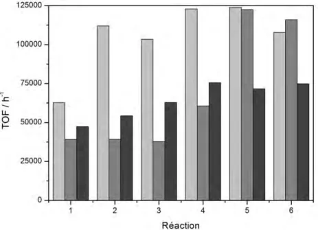
Les catalyseurs au Rh ainsi obtenus ont montré l'influence du support sur l'activité catalytique et l’utilisation du support Fe3O4@SiO2CeO2 a permis d’atteindre une activité
catalytique plus élevée (TOF 125000 h-1). Le catalyseur préparé avec l'oxyde de titane (Fe3O4@SiO2TiO2) a atteint une activité similaire, mais après plusieurs cycles catalytiques.
Le catalyseur préparé avec la silice (Fe3O4@SiO2Cal) a atteint une activité de 40% inférieure
par rapport aux autres (figure 11). La température de conversion maximale pour l'hydrogénation en phase gazeuse du cyclohexène est en accord avec l'activité catalytique observée en phase liquide. Les catalyseurs de Pd ont montré un comportement différent et la meilleure combinaison avec de la silice pour l'hydrogénation en phase liquide, mais les températures pour l’hydrogénation en phase gazeuse a été la même pour tous les supports
Figure 11. L’activité catalytique de Rh@PVP supporté sur Fe3O4@SiO2CeO2 (gris clair), Fe3O4@SiO2TiO2
(gris) et Fe3O4@SiO2Cal (gris foncé) dans l’hydrogenation du cyclohexène. Les conditions de réaction: 6 bar H2,
75 °C et TON = 35600.
Figure 12. L’activité catalytique de Pd@PVP supporté sur Fe3O4@SiO2CeO2 (gris clair), Fe3O4@SiO2TiO2
(gris) et Fe3O4@SiO2Cal (gris foncé) dans l’hydrogenation du cyclohexène. Les conditions de réaction: 6 bar H2,
PVP comme agent stabilisant présente l'inconvénient de lixiviation dans des solvants polaires, comme les alcools et l'eau, c’est pourquoi l'hydrogénation du phénol a été menée en utilisant du n-hexane comme solvant. L'utilisation de n-hexane rend également inutile l'extraction des produits alors que c’est nécessaire avec l'eau. Les catalyseurs au palladium ont montré la plus grande sélectivité pour la formation de la cyclohexanone, indépendamment du support utilisé (tableur 2). Cependant, le support d'oxyde de titane a amélioré la conversion en cyclohexanol pour toutes les nanoparticules métalliques supportées (figure 13).
Tableur 2. L’hydrogenation du phénol en untilisant organométalliques NPs supporté.a
Entrée Catalyseur Conv.
(%)b
Selectivité (%)b
Cyclohexanone Cyclohexanol Cyclohexane
2 h 20 h 2 h 20 h 2 h 20 h 2 h 20 h 1 Fe3O4@SiO2CalPdPVP 94 100 90 82 6 12 4 6 2 Fe3O4@SiO2CePdPVP 86 99 86 80 12 17 2 3 3 Fe3O4@SiO2TiPdPVP 91 99 82 78 16 19 2 3 4 Fe3O4@SiO2CalRhPVP 100 100 26 1 71 87 3 12 5 Fe3O4@SiO2CeRhPVP 100 100 39 5 61 94 0 1 6 Fe3O4@SiO2TiRhPVP 100 100 12 0 88 99 0 1 7 Fe3O4@SiO2CalRuPVP 93 100 24 1 73 92 3 7 8 Fe3O4@SiO2CeRuPVP 99 100 17 0 83 100 0 0 9 Fe3O4@SiO2TiRuPVP 100 100 0 0 100 100 0 0 a
Les conditions de réaction: phènol (75 µmol), solvant n-hexane (3 mL), catalyseur (36 mg, 3,7 µmol), et substrat/catalyseur = 20, 75 °C, 6 bar H2. b Conversion et selectivité déterminé par CG.
sur Fe3O4@SiO2Cal (noir), Fe3O4@SiO2Ce (rouge) et Fe3O4@SiO2Ti (bleu). Conversion du phènol (carrés
vides) et sélectivité pour cyclohexanol (cercles), cyclohexanone (triangles) et cyclohexane (carrés)
Une autre réaction qui peut se produire est l’hydrodéoxygénation conduisant à l’obtention de cyclohexane en tant que produit. La formation de cyclohexane a été observée principalement avec les supports de silice. Le catalyseur Fe3O4@SiO2CalPdPVP, après un
temps de réaction de 20 h, a montré une sélectivité en 12% en cyclohexane dans des conditions douces (75 °C et 6 bar H2). Les catalyseurs au Rh ont montré une activité très
élevée, ce qui a permis de réaliser la réaction avec un ratio substrat/catalyseur plus élevé (Figure 14). Toutefois, l'augmentation du ratio substrat/catalyseur a conduit à la modification de la sélectivité, tous les catalyseurs ayant montré une réduction de la sélectivité en cyclohexanol et la composition du cyclohexanol et de la cyclohexanone était d'environ 50%
Figure 14. L’hydrogenation/hydrodesoxygénation du phenol en utilisant (a) Fe3O4@SiO2CalRhPVP, (b)
Fe3O4@SiO2CeRhPVP et (c) Fe3O4@SiO2TiRhPVP. TON = 20 (noir) et 200 (bleu). Conversion du phènol
(carrés vides) and selectivité pour cyclohexanol (cercles), cyclohexanone (triangles) and cyclohexane (carrés).
Le catalyseur Fe3O4@SiO2CalPdPVP a également été étudié pour l'hydrogénation du
phénol sous 1 et 3 bar de H2 à 55 ºC (figure 15). La formation de cyclohexène n'a pas été
observée à des pressions inférieures à 6 bar de H2. La conversion du phénol était également
plus faible pour les pressions inférieures (16, 24 et 34% de 1, 3 et 6 bar H2). Cependant, la
(rouge) et 1 bar de H2 (bleu). Conversion du phènol (carrés vides) et selectivité pour cyclohexanol (cercles),
cyclohexanone (triangles) et cyclohexanol (carrés).
Les catalyseurs de Pd ont été calcinés sous air à 300 °C pendant 2 h pour éliminer la PVP et évaluer l'hydrogénation du phénol en phase aqueuse (tableur 3). Le mélange réactionnel dans l'eau a montré 100 % de sélectivité en cyclohexanone. Seul le catalyseur avec de l'oxyde de cérium a conduit à 7 % de cyclohexane alors que celui avec de l'oxyde de titane a montré 100 % de conversion du phénol. Les catalyseurs au Pd calcinés ont montré une activité légèrement améliorée par rapport aux catalyseurs de Pd bruts. L'inconvénient de l'eau en tant que solvant est l'impossibilité de séparer magnétiquement les catalyseurs du fait de la plus grande affinité des supports avec l’eau.
Entrée Catalyseur Conv.
(%)b Selectivité (%)
b
cyclohexanone cyclohexanol cyclohexane
1 Fe3O4@SiO2CalPdPVPc 79 100 0 0 2 Fe3O4@SiO2CeO2PdPVPc 70 93 0 7 3 Fe3O4@SiO2TiO2PdPVPc 100 100 0 0 4 Fe3O4@SiO2CalPdPVPd 98 95 5 0 5 Fe3O4@SiO2CeO2PdPVPd 25 95 5 0 6 Fe3O4@SiO2TiO2PdPVPd 99 96 4 0 a
Les conditions de réaction: phènol (75 µmol, in 3 mL c water ou d n-hexane), catalyseur (36 mg, 3,7 µmol) et substrat/catalyseur = 20, 75 °C, 6 bar H2. b Conversion and selectivité déterminé par CG.
Mots clés: Catalyse, support magnétique, nanoparticule, silice, oxyde de cérium, oxyde de titane, hydrogénation, palladium, rhodium, ruthénium et or
APTES. (3-Aminopropyl)triethoxysilane
Au@PVP. Polyvinylpirrolidone stabilized gold nanoparticles BE. Binding energy
BET. Brunauer-Emmett-Teller
COD. Crystallographic open database DSC. Diferential scanning calorimetry EDS. Energy-dispersive X-ray spectroscopy FAAS. Flame atomic absorption spectroscopy FC/ZFC. Field cooling/Zero field cooling Fe3O4@SiO2.Silica-coated magnetite
Fe3O4@SiO2Pd. Palladium catalyst supported in Fe3O4@SiO2
Fe3O4@SiO2NH2. Amino functionalized silica-coated magnetite
Fe3O4@SiO2NH2Pd. Palladium catalyst supported in Fe3O4@SiO2NH2
Fe3O4@SiO2NH2PdPVP-1. Pd@PVP-1 NPs supported in Fe3O4@SiO2NH2
Fe3O4@SiO2NH2RhPVA. Rh@PVA NPs supported in Fe3O4@SiO2NH2
Fe3O4@SiO2Cal. Calcined silica-coated magnetite
Fe3O4@SiO2CalPd. Palladium catalyst supported in Calcined silica-coated magnetite
Fe3O4@SiO2CalNH2. Amino functionalized calcined silica-coated magnetite
Fe3O4@SiO2CalNH2Pd. Palladium catalyst supported in Fe3O4@SiO2CalNH2
Fe3O4@SiO2CalNH2PdPVP-1. Pd@PVP-1 NPs supported in Fe3O4@SiO2CalNH2
Fe3O4@SiO2CeO2. Ceria deposited on silica-coated magnetite
Fe3O4@SiO2TiO2. Titania deposited on silica-coated magnetite
Fe3O4@SiO2CalPdPVP. Pd@PVP NPs supported in Fe3O4@SiO2Cal
Fe3O4@SiO2CalRhPVP. Rh@PVP NPs supported in Fe3O4@SiO2Cal
Fe3O4@SiO2CalRuPVP. Ru@PVP NPs supported in Fe3O4@SiO2Cal
Fe3O4@SiO2CeO2PdPVP. Pd@PVP NPs supported in Fe3O4@SiO2CeO2
Fe3O4@SiO2CeO2RhPVP. Rh@PVP NPs supported in Fe3O4@SiO2CeO2
Fe3O4@SiO2CeO2RuPVP. Ru@PVP NPs supported in Fe3O4@SiO2CeO2
Fe3O4@SiO2TiO2PdPVP. Pd@PVP NPs supported in Fe3O4@SiO2TiO2
Fe3O4@SiO2TiO2RhPVP. Rh@PVP NPs supported in Fe3O4@SiO2TiO2
Fe3O4@SiO2TiO2RuPVP. Ru@PVP NPs supported in Fe3O4@SiO2TiO2
FID. Flame ionization detector
FTIR. Fourrier transformed infrared spectroscopy GC. Gas chromatography
ICDD. International Centre for Diffraction Data
ICP OES. Inductively coupled plasma optical emission spectroscopy IF-USP. Instituto de Física da Universidade de São Paulo
IMP. Impregnation method for the preparation of supported metal nanoparticles IQ-USP. Instituto de Química da Universidade de São Paulo
LCC-CNRS. Laboratoire de Chimie de Coordination du Centre National de la Recherche Scientifique
PVA. Polyvinyl alcohol PVP. Polyvinylpirrolidone
Rh@PVA. Polyvinyl alcohol stabilized rhodium nanoparticles Rh@PVP. Polyvinylpirrolidone stabilized rhodium nanoparticles Ru(COD)(COT). (cyclo-octadiene)(cyclo-octatriene)ruthenium(0) Ru@PVP. Polyvinylpirrolidone stabilized ruthenium nanoparticles
SI. Sol-immobilization method for the preparation of supported metal nanoparticles SQUID. Superconducting quantum interference device
TEM/HRTEM. Transmission electron microscopy/High resolution transmission electron microscopy
TEO. Titanium(IV) 2-ethylhexyloxide TEOA. Triethanolamine
TEOS. Tetraethoxysilane
TG/DTG. Thermogravimetry/derivative thermogravimetry THF. Tetrahydrofuran
TOF. Turnover frequency TON. Turnover number
TTIP. Titanium(IV) isopropoxide XRD. X-ray diffraction
Figure 1. (a) L'influence de le temps de la réaction sur la taille des particules de Fe3O4@SiO2
et (b) micrographie obtenue par MET. ... 2 Figure 2. (a) TG (ligne solide) et DTG (ligne pointillés) obtenu avec l’énchantilion Fe3O4@SiO2 sous l’air (noir) et azote (rouge). (b) DSC obtenues pour la magnétite pure
(rouge) et de magnétite revêtues d'oxyde de silicium (noir). ... 3 Figure 3. Micrographie obtenue par MET d’échantilion Fe3O4@SiO2 aprés calcination... 3
Figure 4. Mesures magnétiques de Fe3O4@SiO2. ... 4
Figure 5. Micrographie de Fe3O4@SiO2TiO2 obtenu par (a) MET et (b) MEHR. ... 5
Figure 6. Micrographie obtenue par MET de Fe3O4@SiO2CeO2. ... 6
Figure 7. Micrographie obtenue par MET de (a) Rh@PVP NPs et de (b) Fe3O4@SiO2NH2RhPVA. ... 9
Figure 8. L’activité du Fe3O4@SiO2Pd (gris clair), Fe3O4@SiO2NH2Pd (gris) et
Fe3O4@SiO2CalNH2Pd (gris foncé) dans l’hydrogénation du cyclohexène. Les conditions de
réaction: 75 ºC, 6 bar H2 et TON 10000. ... 10
Figure 9. Micrographie obtenu par MET: (a) Rh@PVP, (b) Pd@PVP et (c) Ru@PVP. ... 11 Figure 10. Micrographie obtenu par MET: (a) Rh@PVP, (b) Pd@PVP et (c) Ru@PVP NPs supporté sur (') Fe3O4@SiO2Cal, ('') Fe3O4@SiO2CeO2 et (''') Fe3O4@SiO2TiO2. ... 12
Figure 11. L’activité catalytique de Rh@PVP supporté sur Fe3O4@SiO2CeO2 (gris clair),
Fe3O4@SiO2TiO2 (gris) et Fe3O4@SiO2Cal (gris foncé) dans l’hydrogenation du cyclohexène.
Les conditions de réaction: 6 bar H2, 75 °C et TON = 35600. ... 13
Figure 12. L’activité catalytique de Pd@PVP supporté sur Fe3O4@SiO2CeO2 (gris clair),
Fe3O4@SiO2TiO2 (gris) et Fe3O4@SiO2Cal (gris foncé) dans l’hydrogenation du cyclohexène.
Les conditions de réaction: 6 bar H2, 75 °C et TON = 10000. ... 13
Figure 13. L’hydrogenation/hydrodesoxygénation du phenol en utilisant (a) Pd, (b) Ru et (c) Rh NPs supporté sur Fe3O4@SiO2Cal (noir), Fe3O4@SiO2Ce (rouge) et Fe3O4@SiO2Ti
(bleu). Conversion du phènol (carrés vides) et sélectivité pour cyclohexanol (cercles), cyclohexanone (triangles) et cyclohexane (carrés) ... 15 Figure 14. L’hydrogenation/hydrodesoxygénation du phenol en utilisant (a) Fe3O4@SiO2CalRhPVP, (b) Fe3O4@SiO2CeRhPVP et (c) Fe3O4@SiO2TiRhPVP. TON = 20
Figure 15. L’hydrogenation/hydrodesoxygénation du phenol en utilisant Fe3O4@SiO2CalPdPVP. 6 (noir), 3 (rouge) et 1 bar de H2 (bleu). Conversion du phènol
(carrés vides) et selectivité pour cyclohexanol (cercles), cyclohexanone (triangles) et cyclohexanol (carrés). ... 17 Figure 1.1. Illustration of different preparation methods of supported metal nanoparticles. Adapted from Okumura et al.22. ... 48 Figure 1.2. Magnetic separation of silica-coated magnetite ... 70 Figure 3.1. Constructive reflection of an X-ray beam. ... 92 Figure 3.2. Illustration of a transmission electron microscope ... 93 Figure 3.3. Scheme of the hydrogenation system ... 100 Figure 3.4. Example of the determination of TOF value ... 102 Figure 4.1. Micrographs obtained by TEM of the silica-coated magnetite prepared with reaction time of (a) 1h, (b) 2 h – 20.1 ± 1.3 nm, (c) 6 h – 28.0 ± 2.0 nm, (d) 12 h – 31.2 ± 1.0 nm, (e) 24 h – 33.8 ± 1.2 nm and (f) 48 h – 34.7 ± 1.2 nm. The corresponding size distribution histograms fitted to Gaussian function are shown in ('). ... 106 Figure 4.2. Silica-coated magnetite particle size as a function of reaction time. ... 107 Figure 4.3. TG (solid) and DTG (dashed) obtained with the Fe3O4@SiO2 at a heating rate of
10 ºC min-1 and dynamics atmosphere of air (black) and nitrogen (red). ... 109 Figure 4.4. TG curves (solid) and DTG (dashed) obtained with (a) oleic acid and (b) IGEPAL CO-520 at a heating rate of 10 ºC min-1 and dynamic atmosphere of air (black) and of nitrogen (red). ... 109 Figure 4.5. DSC curves obtained for (a) pure magnetite and (b) silica-coated magnetite. ... 110 Figure 4.6. Micrograph obtained by TEM of Fe3O4@SiO2 after calcination and the
correspondent size distribution histogram fitted to a Gaussian function ... 111 Figure 4.7. XRD diffraction pattern for silica-coated magnetite (a) before and (b) after calcination... 112 Figure 4.8. Magnetization curves for the materials Fe3O4@SiO2 (solid) and Fe3O4@SiO2Cal
(dashed). ... 113 Figure 4.9. ZFC and FC curves for Fe3O4@SiO2 (solid) and Fe3O4@SiO2Cal (dashed)
obtained under magnetic field of 50Oe. ... 115 Figure 4.10. XPS spectra of O 1s, Si 2p and C 1s core-level obtained with Fe3O4@SiO2 ... 117
Figure 4.12. Characterization of Fe3O4@SiO2TiO2: micrograph obtained by (a) TEM and by
(b) HRTEM and Energy dispersive X-ray spectroscopy (EDS) analysis of the (c) particle surface and (d) whole particle. ... 122 Figure 4.13. XRD pattern for Fe3O4@SiO2TiO2 (a) and Fe3O4@SiO2 (b). ... 123
Figure 4.14. XPS spectra of O 1s, Si 2p, C 1s and Ti 2p core-level obtained with Fe3O4@SiO2TiO2 ... 124
Figure 4.15. Characterization of Fe3O4@SiO2CeO2: (a) micrograph obtained by TEM, (b)
Energy dispersive X-ray spectroscopy (EDS) analysis and (c) Lognormal adjusted size distribution histogram. ... 127 Figure 4.16. XRD pattern of (a) Fe3O4@SiO2CeO2 and (b) Fe3O4@SiO2. The peaks attributed
to magnetite are indicated with ■ and to ceria with *. ... 128 Figure 4.17. XPS spectra of O 1s, Si 2p, C 1s and Ce 3d core-level obtained with Fe3O4@SiO2CeO2 ... 129
Figure 4.18. Hydrogenation of cyclohexene by Rh catalysts containing 0.1 (empty squares) and 1.5 (squares) wt% Rh supported on Fe3O4@SiO2NH2 and reduced by H2. Reaction
conditions: 6 bar H2, 75 ºC and substrate/catalyst = 35600. ... 133
Figure 4.19. Hydrogenation of cyclohexene by Rh containing catalysts (0.1 to 1.5 wt% Rh) supported in Fe3O4@SiO2NH2 and reduced by NaBH4. Reaction conditions: 6 bar H2, 75 ºC
and substrate/catalyst molar ratio = 35600. Metal content: 0.1 (squares), 0.5 (empty squares), 1.0 (circle) and 1.5 % (circle). ... 135 Figure 4.20. TEM micrographs of supported Rh catalysts reduced by NaBH4: (a) 0.1; (b) 0.5;
(c)1.0 and (d) 1.5 wt% Rh. The corresponding size distribution histograms fitted to Gaussian function are shown in (a'), (b'), (c') and (d'). ... 136 Figure 4.21. Hydrogenation of benzene by Rh containing catalysts (1.5 wt% Rh) supported on Fe3O4@SiO2NH2 and reduced by NaBH4. Reaction conditions: 6 bar H2, 75 ºC and
substrate/catalyst molar ratio = 500. ... 138 Figure 4.22. Hydrogenation of (a) cyclohexene and (b) benzene by Rh containing catalysts (1.5 wt% Rh) supported on Fe3O4@SiO2NH2 and reduced by N2H4. Reaction conditions: 6
bar H2, 75 ºC and substrate/catalyst molar ratio= 35600 (cyclohexene) and 500 (benzene). 140
Figure 4.23. TEM micrograph of supported Rh catalyst (1.5 wt.%) reduced by hydrazine and the correspondent size distribution histogram fitted to a Gaussian function. ... 140
Figure 4.25. Hydrogenation of cyclohexene by aqueous colloidal Rh@PVA NPs at different temperatures. Reaction conditions: 6 bar H2, 25-100 ºC and substrate/catalyst molar ratio =
35600. ... 145 Figure 4.26. Catalytic activity of Rh@PVA in the hydrogenation of cyclohexene in function of substrate/catalyst ratio. Reaction conditions: 6 bar H2, 75 ºC and substrate/catalyst ratio =
35600-569600. ... 146 Figure 4.27. Hydrogenation of (a) cyclohexene and (b) benzene by Rh@PVA supported in Fe3O4@SiO2NH2 (1.5 wt%). Reaction conditions: 6 bar H2, 75 ºC and substrate/catalyst molar
ratio = 35600 (cyclohexene) and 1000 (benzene). ... 149 Figure 4.28. Micrograph obtained by TEM of Fe3O4@SiO2NH2RhPVA (A) as prepared and
(B) after benzene hydrogenation cycle 4 and the correspondent size distribution histogram fitted to a Gaussian function. ... 149 Figure 4.29. Activity of Fe3O4@SiO2Pd (light grey), Fe3O4@SiO2NH2Pd (grey) and
Fe3O4@SiO2CalNH2Pd (dark grey) in the hydrogenation of cyclohexene. Reaction conditions:
75 ºC, 6 bar H2 and TON 10,000. ... 151
Figure 4.30. Hydrogenation of cyclohexene by Pd containing catalysts (1.0 wt% pd) supported in (a) Fe3O4@SiO2, (b) Fe3O4@SiO2NH2 and (c) Fe3O4@SiO2CalNH2. Reaction
conditions: 6 bar H2, 75 ºC and substrate/catalyst molar ratio = 10000. ... 153
Figure 4.31. Hydrogenation of cyclohexene by colloidal Pd@PVP-1 (1.0 wt% Rh) supported in Fe3O4@SiO2, Fe3O4@SiO2NH2 (squares) and Fe3O4@SiO2CalNH2 (circles). Reaction
conditions: 6 bar H2, 75 ºC and substrate/catalyst molar ratio = 10000. ... 156
Figure 4.32. Structure of the organometallic compounds used: (a) Rh(C3H5)3, (b)
Ru(COD)(COT) and (c) Pd2dba3 ... 159
Figure 4.33. Micrograph obtained by TEM of (a) Rh@PVP, (b) Pd@PVP and (c) Ru@PVP. The corresponding size distribution histograms fitted to Gaussian function are shown in (a'), (b') and (c'). Scale bar = 50 nm. ... 160 Figure 4.34. TEM micrographs of (a) Rh@PVP, (b) Pd@PVP and (c) Ru@PVP NPs supported on Fe3O4@SiO2Cal, (') Fe3O4@SiO2CeO2 and ('') Fe3O4@SiO2TiO2. Scale bar = 50
nm... 161 Figure 4.35. Catalytic hydrogenation of cyclohexene using Rh@PVP supported NPs on (a) Fe3O4@SiO2Cal, (b) Fe3O4@SiO2CeO2 and (c) Fe3O4@SiO2TiO2. Reaction conditions: 6 bar
gray). Reaction conditions: 6 bar H2 and 75 °C and TON of 35600. ... 165
Figure 4.37. Catalytic hydrogenation of cyclohexene using Pd@PVP supported NPs (a) Fe3O4@SiO2Cal, (b) Fe3O4@SiO2CeO2 and (c) Fe3O4@SiO2TiO2. Reaction conditions: 6 bar
H2, 75 °C and substrate/catalyst molar ratio = 10,000. ... 166
Figure 4.38. Catalytic activity in the hydrogenation of cyclohexene of Pd@PVP supported NPs in Fe3O4@SiO2CeO2 (light gray), Fe3O4@SiO2TiO2 (gray) and Fe3O4@SiO2Cal (dark
gray). Reaction conditions: 6 bar H2, 75 °C and TON of 10,000. ... 168
Figure 4.39. Gas composition by mass spectrometry of hydrogenation of cyclohexene in gas phase by Fe3O4@SiO2CalRhPVP (black), Fe3O4@SiO2CeO2RhPVP (light gray) and
Fe3O4@SiO2TiO2RhPVP (dark gray). Mass response of (a) cyclohexane (m/z = 84) and (b)
benzene (m/z = 78)... 170 Figure 4.40. Gas composition obtained by mass spectrometry during dehydrogenation of cyclohexene in gas phase by Fe3O4@SiO2CalRhPVP (black), Fe3O4@SiO2CeO2RhPVP (light
gray) and Fe3O4@SiO2TiO2RhPVP (dark gray). Mass response of benzene (m/z = 78). ... 171
Figure 4.41. Gas composition by mass spectrometry of hydrogenation of cyclohexene in gas phase by Fe3O4@SiO2CalPdPVP (black), Fe3O4@SiO2CeO2PdPVP (light gray) and
Fe3O4@SiO2TiO2PdPVP (dark gray). Mass response of (a) cyclohexane (m/z = 84) and (b)
benzene (m/z = 78)... 172 Figure 4.42. Conversion of CO (black) to CO2 (gray) by (a) Fe3O4@SiO2CalRhPVP, (b)
Fe3O4@SiO2CeO2RhPVP, (c) Fe3O4@SiO2TiO2RhPVP and (d) reuse of the
Fe3O4@SiO2TiO2RhPVP catalyst. ... 174
Figure 4.43. Phenol adsorption by basic and acidic sites and enhanced product selectivity. Adapted from Cheng et al.187 ... 175 Figure 4.44. Hydrogenation and hydrodeoxygenation of phenol reaction and side reactions. ... 176 Figure 4.45. Phenol hydrogenation/hydrodeoxygenation using Fe3O4@SiO2CalPdPVP
(black), Fe3O4@SiO2CeO2PdPVP (red) and Fe3O4@SiO2TiO2PdPVP (blue). Conversion of
phenol (empty squares) and selectivity to cyclohexanol (circles), cyclohexanone (triangles) and cyclohexane (squares)... 178 Figure 4.46. Phenol hydrogenation/hydrodeoxygenation using Fe3O4@SiO2CalRuPVP
Figure 4.47. Phenol hydrogenation/hydrodeoxygenation using Fe3O4@SiO2CalRhPVP
(black), Fe3O4@SiO2CeO2RhPVP (red) and Fe3O4@SiO2TiO2RhPVP (blue). Conversion of
phenol (empty squares) and selectivity to cyclohexanol (circles), cyclohexanone (triangles) and cyclohexane (squares) ... 180 Figure 4.48. Phenol hydrogenation/hydrodeoxygenation using Fe3O4@SiO2CalRhPVP (a),
Fe3O4@SiO2CeO2RhPVP (b) and Fe3O4@SiO2TiO2RhPVP (c) with substrate/catalyst molar
ratio = 20 (black) and 200 (blue). Conversion of phenol (empty squares) and selectivity to cyclohexanol (circles), cyclohexanone (triangles) and cyclohexane (squares). ... 181 Figure 4.49. Phenol hydrogenation/hydrodeoxygenation using Fe3O4@SiO2CalPdPVP at H2
pressure of 6 bar (black), 3 (red) and 1 bar (blue). Conversion of phenol (empty squares) and selectivity to cyclohexanol (circles), cyclohexanone (triangles) and cyclohexane (squares). 183 Figure 4.50. Micrograph obtained by TEM of (a) Au@PVP, (b) Rh@PVP and (c)Ru@PVP after benzyl alcohol oxidation and the correspondent size distribution histogram adjusted to a Gaussian function. Scale bar = 50 nm... 186 Figure 4.51. Structure of AuCl(THT) ... 188 Figure 4.52. Infrared transmission spectrum of AuCl(THT) obtained using CsBr pellets ... 189 Figure 4.53. Micrograph obtained by TEM of gold particles prepared by reduction of AuCl(THT) with (a) NaBH4 and PVP and (a) H2 and hexadecylamine. ... 190
Figure 4.54. Micrograph obtained by TEM of Au@PVP (a) after and (b) before dialysis and (a’) the size distribution histogram adjusted to a Gaussian function of the Au@PVP after dialysis. ... 192 Figure 4.55. Micrograph obtained by TEM of Rh@PVA prepared using as precursor (a) Rh(C3H5)3 and (b) RhCl3.xH2O. Scale bar = 100 nm. ... 193
Figure 4.56. Micrograph obtained by TEM of Rh@PVA prepared by organometallic approach after hydrogenation of cyclohexene. ... 194
Tableur 1. L’activité des catalyseurs de Rh préparé pour imprégnation ... 8 Tableur 2. L’hydrogenation du phénol en untilisant organométalliques NPs supporté.a ... 14 Tableur 3. L’hydrogenation du phénol en untilisant Pd NPs supporté et calciné et l’eau or n-hexane comme solvanta ... 18 Table 4.1. Summary of silica-coated magnetite properties obtained by different techniques. ... 116 Table 4.2. Binding energies of O 1s, Si 2p and C 1s core levels observed in XPS analysis of Fe3O4@SiO2 ... 117
Table 4.3. Binding energies of O 1s, Si 2p, C 1s and Ti 2p core levels observed in XPS analysis of Fe3O4@SiO2TiO2 ... 124
Table 4.4. Binding energies of O 1s, Si 2p, C 1s and Ce 3d core levels observed in XPS analysis of Fe3O4@SiO2CeO2 ... 129
Table 4.5. Catalytic activity of supported Rh catalysts reduced by H2 in the hydrogenation of
cyclohexene.a ... 133 Table 4.6. Catalytic activity of supported Rh catalysts reduced by NaBH4 in the
hydrogenation of cyclohexene and Rh NPs size... 135 Table 4.7. Catalytic activity of supported Rh catalyst (1.5 wt%) reduced by NaBH4 in the
hydrogenation of benzene.a ... 138 Table 4.8. Catalytic activity of supported Rh catalyst (1.5 wt%) reduced by hydrazine.a .... 139 Table 4.9. Catalytic activity of colloidal suspension of Rh@PVA in the hydrogenation of cyclohexene.a ... 144 Table 4.10. Catalytic activity of Fe3O4@SiO2NH2RhPVA catalyst.a ... 148
Table 4.11. Quantification of Pd in the magnetic supports by FAAS ... 150 * Below the quantification limit. ... 150 Table 4.12. Catalytic activity of Pd catalyst prepared by IMP in the hydrogenation of cyclohexene.a ... 152 Table 4.13.Catalytic activity of Pd catalyst prepared by SI of Pd@PVP-1 in the hydrogenation of cyclohexene.a ... 156 Table 4.14. Influence of the support on the catalytic activity of immobilized Rh@PVP NPs prepared by organometallic approach in the hydrogenation of cyclohexene.a ... 164
Table 4.16. Hydrogenation of phenol using supported metal NPs obtained by organometallic approach.a ... 176 Table 4.17. Hydrogenation of phenol using supported Rh NPs obtained by organometallic approach.a ... 181 Table 4.18. Hydrogenation of phenol with calcined Pd using water and n-hexane as solvent.a ... 184 Table 4.19. Oxidation of Benzyl alcohol ... 185 Table 4.20. Elemental analysis of AuCl(THT) ... 189
1. Introduction ... 41
1.1. Nanocatalysis ... 41 1.1.1. Structure and size sensitive and insensitive reactions...43 1.2. Nanocatalyst ... 44 1.2.1. Supported nanocatalysts...46 1.2.2. Synthesis of supported nanocatalysts ...47 1.2.3. Catalytic activity of supported nanocatalysts ...52
1.2.3.1. Supported Palladium nanocatalysts ...54 1.2.3.2. Supported Rhodium nanocatalysts ...63 1.2.3.3. Supported Ruthenium nanocatalysts ...64 1.2.3.4. Deactivation of supported nanocatalysts ...67
1.3. Magnetically recoverable and recyclable nanocatalysts ... 68 1.4. Justification ... 72
2. Objectives ... 74
2.1. General ... 74 2.2. Specifics ... 743. Materialsand Methods ... 76
3.1. Materials ... 76 3.1.1. Reagents ...76 3.1.2. Equipments ...77 3.2. Methods ... 78 3.2.1. Synthesis of silica-coated magnetite supports ...783.2.1.1. Functionalization of silica surface with amine groups ...79 3.2.1.2. Quantification of amine groups ...80
3.2.2. Deposition of metallic oxides in silica-coated magnetite ...81
3.2.2.1. Deposition of titanium oxide ...81 3.2.2.2. Deposition of cerium oxide ...81
3.2.3. Synthesis of metal precursors ...82
3.2.3.1. Synthesis of Tris(allyl)Rhodium(III) complex ...82 3.2.3.2. Synthesis of Chloro(tetrahydrothiophene)gold(I) ...82
3.2.4. Synthesis of metal nanoparticles ...83
3.2.4.1. Synthesis of palladium nanoparticles by reduction of metal salts ...83 3.2.4.2. Synthesis of rhodium nanoparticles by reduction of metal salts ...84
3.2.5. Catalysts preparation by impregnation method ... 86
3.2.5.1. Rhodium catalysts ... 86 3.2.5.2. Palladium catalysts ... 87
3.2.6. Catalyst preparation by immobilization of preformed metal nanoparticles ... 87
3.2.6.1. Immobilization of preformed metal nanoparticles prepared with salt precursors ... 87 3.2.6.2. Immobilization of preformed metal nanoparticles prepared with organometallic precursors .... 88
3.2.7. Catalytic reactions ... 89
3.2.7.1. Hydrogenation of cyclohexene and benzene in liquid phase ... 89 3.2.7.2. Hydrogenation of cyclohexene in gas phase ... 89 3.2.7.3. Hydrogenation of phenol in liquid phase ... 90 3.2.7.4. Oxidation of Benzyl alcohol ... 91
3.3. Analysis techniques ... 91 3.3.1. X-ray diffraction ... 91 3.3.2. Transmission electron microscopy ... 93 3.3.3. Thermogravimetry Analysis and Differential Scanning Calorimetry ... 94 3.3.4. Inductively Coupled Plasma Optical Emission Spectroscopy and Flame Atomic Absorption Spectroscopy ... 95 3.3.5. Gas Chromatography... 96 3.3.6. Magnetic measurements ... 98 3.3.7. Hydrogen monitoring system ... 99 3.3.8. X-ray photoelectron spectroscopy (XPS) ... 102
4. Results and Discussion ... 104
4.1. Development of magnetic supports ... 104 4.1.1. Preparation and thermal behavior of silica-coated magnetite ... 105 4.1.2. Preparation of titania-coated magnetite: post-coating process ... 118 4.1.3. Preparation of ceria-coated magnetite: post coating process... 126 4.2. Development of magnetically recoverable metal nanoparticle catalysts ... 131
4.2.1. Rhodium catalysts prepared using RhCl3.xH2O ... 131
4.2.1.1. Rhodium catalysts prepared by the impregnation method ... 131 4.2.1.2. Rhodium catalysts prepared by the sol-immobilization method... 142
4.2.2. Catalysts prepared with Na2PdCl4 ... 150
4.2.2.1. Palladium catalysts prepared by the impregnation method ... 150 4.2.2.2. Palladium catalysts prepared by the sol-immobilization method ... 154
4.3.1. Synthesis of Rh, Pd and Ru NPs stabilized with PVP ... 158 4.3.2. Rh, Ru and Pd catalysts prepared by the sol-immobilization method ... 160 4.3.3. Catalytic reactions ... 162
4.3.3.1. Hydrogenation of cyclohexene ... 162 4.3.3.2. Hydrogenation of phenol ... 174 4.3.2.4. Benzyl alcohol oxidation ... 184
4.3.3. Difficulties found in the preparation of preformed metal nanoparticles... 187
4.3.3.1. Gold nanoparticles stabilized with PVP ... 187 4.3.3.2. Rhodium nanoparticles with PVA and organometallic approach ... 192
5. Conclusion ... 195
6. Perspectives ... 200
7. References ... 201
1. INTRODUCTION
1.1. Nanocatalysis
The transformation of raw materials into countless valuable chemical products involves catalytic processes in at least one step. Catalysis is not only a tool for the chemical industry, but is also considered as a key to solve environmental challenges, mainly related to energy production and consumption and to waste minimization or prevention.1 Catalysis is one of the 12 principles of green chemistry2 and can be directly related to the principles of atom economy, design for energy efficiency and derivatives reduction.
Traditionally, catalysis is divided in two major groups: homogeneous and heterogeneous catalysis. Homogeneous catalysis is defined by the presence of catalyst and substrate in the same phase and soluble molecular and ionic compounds are used as catalysts. On the other hand, heterogeneous catalysis is defined by the presence of catalyst and substrate in different phases. Typically in the heterogeneous catalysis, metals and metal oxides are used as catalysts. Due to the different phases, the separation of heterogeneous catalysts from the products is easier and more effective when compared to homogeneous catalysts. Homogeneous catalysts may require solvent addition, distillation and other time and energy consuming procedures. However, homogeneous catalysts are more selective and more active than heterogeneous catalysts. Even though, homogeneous catalysts are less interesting for industrial processes than heterogeneous catalyst due to the onerous separation, the increase in the regulation of trace amounts of catalytic moieties in commodity chemicals and pharmaceutical products, and the typical higher price.3
The effort to surpass the disadvantages of homogeneous catalysis and to integrate the advantages of heterogeneous catalysis brought the attention of the catalysis research to nanocatalysis. The term nanocatalysis adopted by the literature corresponds to application of nanoparticles as catalysts. For example, bulk gold does not show catalytic activity, but when reduced to nanoscale (less than 20 nm) gold nanoparticles act as a remarkable catalyst for diversified reactions.4 A typical example of the gold nanoparticles catalytic activity is the CO oxidation demonstrated by Haruta.5 The remarkable activity and selectivity of metal and metal oxide nanocatalysts are basically related to two effects: the size effect and the electronic effect.
The size effect is considered because there is a huge increase of surface area with the reduction of bulk metals to nanoscale. This means also that the amount of corner and edge atoms, with lower coordination number, are increased in the nanoscale. The metal atoms with low-coordination number in a solid metal structure are often responsible for the active sites of the catalyst.6
The electronic effect is mainly related to the surface stress. With the reduction of the bulk metal to nanoscale arises a surface stress that corroborates to an increase of broken bonds of surface atoms when compared to the bulk, resulting in an increase of surface energy that is not negligible. The surface stress also contributes to the decrease of the lattice parameter by inducing a pressure towards the center of the nanoparticle. Then, in many cases the equilibrium shape of a nanoparticle does not correspond to the equilibrium shape of the bulk material, and as consequence different facets are displayed in the nanoparticle. The outcome induced by the surface stress directly influences the electronic band structure: the valence band is reduced and its center of gravidity is shifted on the way to the Fermi level. These changes in electronic band structure affect directly the chemisorption of the substrate on the surface of the catalyst in a catalytic process, resulting in different activity and selectivity as
compared to the bulk catalyst.7 Even though the size effect is related to the enhancement of surface area, the electronic effects are also connected with nanoparticle size, since the surface stress is proportional to the nanoparticle size and morphology. As a result, the variation of nanoparticle size and shape also affects their catalytic performance, which opens a huge possibility of studies in this area.8
1.1.1. Structure and size sensitive and insensitive reactions
The idea of size reduction in order to maximize the surface area to obtain more surface metallic atoms can suggest higher activity, once there is more metal able to interact with substrate. However, this is not always true. It is clear that we have a inumerous combination of catalyst, substrate and type of reaction, but those combinations will resume into three main groups: size-insensitive, negative and positive size-sensitive reactions.9 These groups are characterized by the behavior of the turnover frequency (TOF, mol substrate converted per mol (normalized by surface atom) catalyst per time) as function of particle size. The size-insensitivity is characterized by the independence of TOF with nanoparticle size. The positive size-sensitivity is observed when the TOF increases with the decrease in nanoparticle size and the negative size-sensitivity observed when the TOF decreases.9-10
The size-sensitivity dependence is related to the particle surface characteristics, because the chemical properties of the substrate bond that needs to be activated will determined the characteristics of surface atom where the lowest activation energy can be achieved.10 For the formation or dissociation of π-bond there is a step-edge atom dependence, which leads to negative size-sensitivity due to the reduction of this type of atom on particle surface with decrease in particle size.9 On the other hand, reaction where the cleavage of σ
C-C bonds is limiting typically shows a positive size-sensitivity.9 The hydrogenation of hydrocarbons is typically size-insensitive reactions.10 On the same way of nanoparticle size, the nanoparticles structure can also play a role in the characteristic of size-sensitivity because some structures can result in the presence of more surface atom of certain type.9-10
1.2. Nanocatalyst
The efforts to develop nanocatalysts started from the initial observations made by different research groups concerning the advantages of using nanoparticles as catalysts:11
1) The possibility of the size and shape control of the nanoparticles by preparation conditions;
2) Colloidal metal nanoparticles can be dispersed in solution like homogeneous catalyst acting in mild conditions (temperature below the boiling point of the solvent);
3) Colloidal metal nanoparticles can be explored as photocatalysts;
4) Metal nanoparticles can be functionalized promoting different catalytic activity; 5) A huge variety of bimetallic and trimetallic nanoparticles with different
composition can be studied;
6) Supported nanocatalysts can be used in gaseous phase reaction;
7) Colloidal and supported metal nanoparticles are commonly more active and selective than conventional industrial catalysts.
Nanoparticle catalysts have already been used successfully in hydrogenation, oxidation, C-C coupling, H2 generation, hydrogenolysis, water splitting and photocatalysis
Their large applicability in increasingly explored green conditions turned nanocatalysts strong candidates to create new sustainable pathway for chemical processes.3b
Nanocatalysts can be used in their colloidal form or as supported nanoparticle catalysts. Usually colloidal nanoparticles are dispersed in a liquid phase and will have limited thermal stability. The liquid phase can be a homogeneous or a heterogeneous mixture with the substrate. Typically, the synthesis of colloidal nanoparticles requires a metal precursor, a reducing agent, a stabilizing agent and a solvent. The ability to disperse nanoparticles in the reaction media, the control of their size and shape can be tuned by choosing the stabilizing agent (polymer, surfactant, charged compounds, organic ligands, etc.), which makes the choice of this reactant extremely important to the design and performance of colloidal nanocatalysts.12 The reducing agent can be replaced for some reactant or condition that destabilizes the metal precursor, for example, when the metal precursor is a zero valance organometallic compound.13
Generally, the colloidal nanoparticles are synthesized, purified and suspended in the reaction media. Depending on the reaction conditions, colloidal nanoparticles are easy deactivated by sintering, morphological changes and leaching.14 Colloidal metal nanoparticles can also show some deactivation due to destabilization of the colloidal suspension.15 Therefore, supported nanoparticles are more versatile when used as catalyst to a variety of reactions because of the easy recovery and enhanced stability. Supported nanoparticles can be successfully explored in a larger range of reaction conditions than colloidal nanoparticles, which can enlarge their applicability as catalyst.
1.2.1. Supported nanocatalysts
Catalysis by supported metal nanoparticles is somehow more complex because of the support, which can present some effects in the catalytic activity. These effects are linked to the interactions of the metal nanoparticles and the reactants with the support, which can direct the catalytic process to different ways of selectivity and activity. The most important effects of support and metal particle interaction are the reverse-spillover and the morphology and edges.7
Reverse-Spillover effect is known as the diffusion of molecular species from the metal surface to the support surface. The reverse-spillover is the most known phenomenon in heterogeneous catalysis and corresponds to the inverse of spillover: the diffusion of adsorbed molecular species from the support to the catalyst particles. This phenomenon provides a different way for chemisorption of reactants on the metal particle surface that can be energetically more favorable. The structures of the support surface and support defects are extremely important to reverse-spillover effect. In some cases, a step of the reaction can occur previously on support surface followed by diffusion of intermediaries to the metal nanoparticles. The addition of promoter on the support may also influence the reverse-spillover effect.16
The Morphology and Edges effect is more related to structure sensitive reactions, as for example, the reduction of NO by CO on Pd that occurs preferably over the plane (1 1 1) of Pd nanoparticles. The high bind energy of CO on Pd edges at low coverage is also an example of structure sensitivity. The supported nanoparticles have the disadvantage (or advantage) of having a part of its structure encapsulated by the support, not being available for catalysis. The resulting encapsulation of the metal nanoparticle by the support is defined as “Strong Metal-Support Interaction (SMSI)” and is used to explain the decreased chemisorption
capacity for CO and H2 on supported metal particles on oxides after heating treatment.17 The
SMSI depends on the nature of the oxide support and also contributes for the decrease of sintering of nanoparticles, which is an advantage compared to colloidal nanoparticles. For example, Ag particles are more strongly attached on CeO2 and Fe3O4 (1 1 1) surfaces than on
MgO (1 0 0), which means that the undesired sintering of nanoparticles occurs easily on MgO (1 0 0).18
The dependence of the catalytic activity with the nanoparticle morphology and support structure requires the rigorous control of their size, shape and composition in order to ensure the reproducibility of their properties and also of the results for a given application. In that context, nanoparticles studies are of interest only if their synthesis is reproducible with a well-defined or tunable size and morphology. The variety of nanocatalysts presented in the literature seems wide, but the synthetic process is not simple. Both colloidal and supported nanoparticles are not the thermodynamically stable form of a metal aggregate. Thus, their synthesis has to be kinetically controlled, with the help of stabilizing agents. The synthesis of supported nanoparticles with a narrow size distribution and good dispersion is still a challenge in the field of nanocatalysis.
1.2.2. Synthesis of supported nanocatalysts
The preparation of supported metal nanoparticles can be achieved by physical, chemical or physicochemical approaches. In the physical approach, also known as the top-down-type method, the supported nanoparticles are prepared from bulk metal treatment in the presence of a support. The treatment of the bulk metal can be done with techniques that provide energies higher than the bond energy of metal as mechanical force, vaporization or
laser ablation, for example. The Physical Vapor Deposition, that includes sputtering deposition method, was originally developed for the production of thin films, but was later adapted for the deposition of metal nanoparticles on liquid (ionic liquids, silicon oil and vegetable oils) and solid substrates.19 In the chemical approach, also known as bottom-up-type method, metal ions are reduced to metal atoms,11 that aggregate to form metal nanoparticles. The aggregation occurs in two steps: nucleation and growth.20 The physicochemical approach involves a combination of the physical and chemical approaches. A good example is the sonoelectrochemistry method that is a combination of sonochemistry (physical) and electrochemistry (chemical).
This thesis will focus exclusively in the preparation of supported metal nanoparticles by chemical approaches. There are innumerous chemical methods to prepare supported metal nanoparticles, among then the impregnation (IMP), sol-immobilization (SI), co-precipitation (CP), deposition-precipitation (DP), deposition-reduction (DR), microemulsion, photochemical, chemical vapor deposition (CVD) and electrochemical reduction (ER) can be highlighted.21 Figure 1.1 shows a schematic illustration of the different methods mentioned for the preparation of supported metal nanoparticles.
Figure 1.1. Illustration of different preparation methods of supported metal nanoparticles. Adapted from Okumura et al.22.
The impregnation (IMP), also called incipient wetness impregnation or dry impregnation, is the most used synthetic approach to prepare supported nanocatalysts. It consists in the mixture of a metal precursor solution and the support, followed by the removal of the solvent with rotary evaporator or centrifugation.21a Then, the metal loaded solid is submitted to a reduction process which can be a reducing agent solution or thermal reduction. If previously to the metal reduction the solid was washed to remove the excess of metal, the metal loading will depend strongly on the affinity of the metal ion with the support. The improvement of this affinity can be done by the functionalization of the support surface with organic ligands that can be further removed by calcination. However, if the ligand is not removed, it can also have an influence the catalytic activity of the supported metal.23
In the co-precipitation (CP) method, the support and the metal ions precipitation occurs at the same time and is followed by reduction.21a As a result, it is possible to obtain metal nanoparticles immersed on the support matrix, and the catalytic activity will depend strongly on the support’s porosity. In some cases, the metal ion can interfere on the polymerization or condensation reaction of the support formation. This influence can lead to a non-desirable material, which will hardly result in a good nanoparticle dispersion and narrow size distribution. An interesting modification of this method is the precipitation of the support in the presence of preformed metal nanoparticles.24 In this way, the preparation of desired materials can be easily achieved, because the size and morphology of the metal nanoparticles were previously controlled in the colloidal synthesis.
The Deposition-precipitation (DP) method was first reported by Haruta et al.25 It consists in preparation of a solution containing the solubilized metal precursor and the support precursor followed by slow precipitation of the support by pH adjustment and reduction of the metal precursor by subsequent calcination process. However, the precipitation-deposition