UNIVERSITÉ DE MONTRÉAL
DEVELOPMENT OF AN AUTOMATED IN-LINE RESIN METERING AND MIXING SYSTEM FOR COMPOSITES IN THE AUTOMOTIVE INDUSTRY
PHILIPPE MURRAY
DÉPARTEMENT DE GÉNIE MÉCANIQUE ÉCOLE POLYTECHNIQUE MONTRÉAL
MÉMOIRE PRÉSENTÉ EN VUE DE L’OBTENTION DU DIPLÔME DE MAÎTRISE ÈS SCIENCES APPLIQUÉES
(GÉNIE AÉROSPATIAL) FÉVRIER 2019
UNIVERSITÉ DE MONTRÉAL
ÉCOLE POLYTECHNIQUE MONTRÉAL
Ce mémoire intitulé :
DEVELOPMENT OF AN AUTOMATED IN-LINE RESIN METERING AND MIXING SYSTEM FOR COMPOSITES IN THE AUTOMOTIVE INDUSTRY
présenté par : MURRAY Philippe
en vue de l’obtention du diplôme de : Maîtrise ès sciences appliquées a été dûment accepté par le jury d’examen constitué de :
M. VADEAN Aurelian, Doctorat, président
M. LABERGE-LEBEL Louis, Ph. D., membre et directeur de recherche M. DUBÉ Robin, M. Sc. A., membre et codirecteur de recherche
DEDICATION
To Mom and Dad, who encouraged me to go on every adventure, especially this one.
ACKNOWLEDGMENTS
The work presented in this thesis was performed at Centre technologique en aérospatiale, École nationale d’aérotechnique and Cegep Édouard-Montpetit with the financial support of Magna Exteriors Inc. and the Natural Sciences and Engineering Research Council.
The completion of this undertaking would not have been possible without the assistance and knowledge of many people. Their contributions are greatly appreciated and sincerely acknowledged. However, I would like to express my deep appreciation to the following:
Mr. Robin Dubé, P.Eng. M.A.Sc., for this project opportunity, his technical assistance throughout the project and his expertise on system design.
Pr. Louis Laberge-Lebel, P. Eng. Ph.D., for his academic rigour and help on how to be a better researcher.
Mr. Bruno Croteau-Labouly, P. Eng. M.A.Sc., for teaching me his project management knowledge and for his good and funny attitude in the workplace.
Daniel Gareau, M.A.Sc. and Carl Ouellet, M.A.Sc. for their help and review on FTIR analysis and polymer chemistry.
To all relatives, friends and others who in one way or another shared their support, financially or morally, thank you.
RÉSUMÉ
L’utilisation de composites structuraux pour les applications automobiles est considérée comme un moyen d’atteindre les nouvelles réglementations à venir en matière d’émission de CO2
des véhicules et les initiatives d’allégement. Le composé de moulage en feuille (SMC) de résine vinyle ester et de fibre de carbone utilisé avec le moulage par compression à chaud est actuellement l'une des solutions les plus performantes pour atteindre les cadences de production élevées requises par l'industrie. Les résines à polymérisation rapide utilisées contiennent une large gamme de charges et d’additifs permettant de réduire le coût de la matière et d’améliorer diverses propriétés. Les entreprises automobiles souhaitant rester compétitives doivent disposer d'une machine permettant le dosage et le mélange de cette résine, ainsi que de ses multiples additifs et charges, pour une distribution en continu à la chaîne de production. Magna International, un des principaux fournisseurs automobiles au monde, est actuellement en phase de validation d’un nouveau sous-châssis SMC et a demandé au Centre technologique en aérospatiale (CTA) de développer un nouveau prototype de système de dosage et de mélange de la résine en ligne. Le projet a été rendu possible grâce à la combinaison d’un étudiant à la maîtrise de l’École polytechnique de Montréal à travers une subvention Mitacs et d’une subvention RDA niveau 3 du CRSNG. Les objectifs du projet étaient de démontrer les performances de l’utilisation d’un mélangeur statique pour obtenir un échantillon de résine homogène, de développer et de fabriquer un nouveau système de dosage et de mélange de résine à deux composants et de valider la performance et les capacités du système. Les systèmes de dosage et de mélange à deux composants présentement disponibles ne sont pas adaptés pour traiter des fluides abrasifs et opérer dans des zones dangereuses de Classe 1 Division 1. En ce qui concerne le mélange, les mélangeurs statiques semblent offrir des performances suffisantes pour mélanger un système de résine à deux composants, mais leur performance est difficile à prédire à l’aide de modèles et de simulations. La performance d'un mélangeur statique de type Kenics a été évaluée par spectroscopie infrarouge à transformée de Fourier à réflexion totale atténuée (ATR-FTIR). Les résultats des travaux ont démontré que l'utilisation d'un mélangeur statique permet de mélanger les composants avec 98% d'homogénéité. Le nouveau système de mélange a été conçu, fabriqué et testé au CTA avant d'être installé et intégré à la ligne expérimentale de production de préimprégné SMC de Magna International. Il offre une large plage de ratio de mélange de 0,8:1 à 320:1 et un débit allant jusqu'à 2500 ml/min à un ratio de mélange nominal de 20,5:1. Le dosage de la machine repose sur un ensemble innovant de pompes à plongeur
multiplex. Il présente une précision de ratio de mélange de ± 1% et une homogénéité de mélange de 98,5% (CoV de 1,5%). Le système est automatisé et ajuste sa cadence de mélange et distribution automatiquement via une boucle de rétroaction de contrôle PID avec la ligne de production. Mots clés: système de mélange en ligne, FTIR, mélange statique, composites, durcissement rapide, industrie automobile
ABSTRACT
The use of structural composites for automotive applications is seen as a means of reaching the upcoming new regulations regarding CO2 emission of vehicles and light-weighting initiatives.
Carbon fibre vinyl ester Sheet Moulding Compound (SMC) used with hot compression moulding is currently one of the leading solutions to achieve high-volume production cadences required by the industry. The fast-cured resins used contain a wide range of fillers and additives to lower the material costs and improve various properties. Automotive companies wishing to remain competitive must have a machine that allows the dosing and mixing of this resin, along with its multiple additives and fillers, for delivery to the production line continuously. Magna International, a world-leading tier one automotive supplier, is currently in the validation phase of a new SMC front car subframe and mandated Centre technologique en aérospatiale (CTA) to develop a new prototype in-line resin metering and mixing system. The project was made possible with the combination of a master’s student from Polytechnique Montréal through a Mitacs grant and an NSERC ARD level 3 grant. The objectives of the project were to demonstrate the performance of using a static mixer to obtain a homogeneous sample, develop and manufacture a new two-component resin metering and mixing system and validate its performance and capabilities. Commercially available two-component metering and mixing system are not capable of processing abrasive fluids while operating in Class 1 Division 1 classified locations. With respect to mixing, static mixers seem to offer adequate performance to mix two-component resin system but their performance is hard to predict with models and simulations. The performance of a Kenics static mixer was evaluated using attenuated total reflection Fourier transform infrared spectroscopy (ATR-FTIR). The use of a static mixer allows the resin and thickening agent to be mixed to 98 % homogeneity. The new system was designed, manufactured and tested at CTA before being installed and integrated to Magna International SMC prepreg development line. It offers a wide range of mixing ratio of 0,8:1 to 320:1 and flow rate of up to 2500 ml/min at a nominal mixing ratio of 20,5:1. The machine’s metering relies on an innovative multiplex assembly of plunger pumps. It has a mixing ratio precision of ± 1 % and a mixing homogeneity of 98,5 % (CoV of 1,5 %). The system is automated and adjusts its production rate automatically through a PID control feedback loop.
TABLE OF CONTENTS
DEDICATION ... iii
ACKNOWLEDGMENTS ... iv
RÉSUMÉ ... v
ABSTRACT ... vii
TABLE OF CONTENTS ... viii
LIST OF TABLES ... xii
LIST OF FIGURES ... xiv
LIST OF APPENDICES ... xviii
CHAPTER 1 INTRODUCTION ... 1
CHAPTER 2 LITERATURE REVIEW ... 4
2.1 Composite materials in the automotive industry ... 4
2.2 Manufacturing processes ... 5
2.3 Applications of composites in the automotive industry ... 8
2.4 Thermoset resins, the importance of mix homogeneity and characterization methods . 10 2.4.1 Mixing homogeneity ... 13
2.5 Mixing technologies for in-line mixing systems ... 20
2.5.1 Static mixing ... 20
2.5.2 Dynamic mixing ... 26
2.5.3 Impingement mixing ... 28
2.6 Pumping technologies for in-line mixing systems ... 30
2.6.1 Positive displacement pumps ... 31
2.6.2 Importance of flow rate linearity ... 35
2.7.1 Hazardous classified locations ... 37
2.7.2 Resin abrasiveness ... 39
2.7.3 Two-component metering and mixing systems ... 39
2.7.4 Summary of current systems limitations ... 43
2.8 Summary and knowledge gaps ... 43
2.9 Project objectives ... 44
CHAPTER 3 DEMONSTRATION OF THE PERFORMANCE OF A STATIC MIXER TO OBTAIN AN HOMOGENEOUS RESIN SAMPLE ... 45
3.1 Materials ... 45
3.2 Equipment ... 46
3.3 Procedure ... 49
3.3.1 FTIR spectroscopy as a technique to evaluate the homogeneity of a resin sample ... 49
3.3.2 Performance of a static mixer to obtain a homogeneous resin sample ... 52
3.3.3 Qualitative evaluation of the impact of mixing ratio variation on mix homogeneity 53 3.4 Results and analysis ... 54
3.4.1 FTIR spectroscopy as a technique to evaluate the homogeneity of a resin sample ... 54
3.4.2 Performance of a static mixer to obtain a homogeneous resin sample ... 62
3.4.3 Qualitative evaluation of the impact of mixing ratio variation on mix homogeneity 64 3.5 Conclusions ... 66
CHAPTER 4 DEVELOPMENT AND MANUFACTURING OF A PROTOTYPE IN-LINE METERING AND MIXING SYSTEM ... 68
4.1 Requirements ... 68
4.1.1 Process requirements ... 68
4.1.2 System requirements ... 69
4.2 Preliminary design ... 73
4.2.1 Resin preparation ... 75
4.2.2 Metering system ... 76
4.2.3 Mixing and delivery ... 77
4.2.4 Equipment technology choice ... 77
4.3 Detailed design ... 80
4.3.1 Computer-assisted design (CAD) ... 81
4.3.2 Automation and control logic ... 85
4.3.3 HMI ... 87
4.3.4 System technical and performance data ... 89
4.4 Manufacturing ... 90
4.4.1 Metering system ... 90
4.4.2 Mixing and delivery system ... 91
4.4.3 Control panel ... 92
CHAPTER 5 VALIDATION OF THE SYSTEM’S PERFORMANCE ... 95
5.1 Flowmeter precision validation ... 95
5.2 Control logic ... 98
5.2.1 Overpressure safety ... 98
5.2.2 Doctor box level control ... 99
5.3 Flow rate linearity ... 101
5.4 Cleaning ... 105
5.5 Mix homogeneity ... 106
5.6 System performance summary ... 107
CHAPTER 6 CONCLUSION AND RECOMMENDATIONS ... 111 6.1 Future work and recommendations ... 112 BIBLIOGRAPHY ... 114
LIST OF TABLES
Table 1 – Price and tensile strength comparison of polyester, vinyl ester and epoxy resins ... 11
Table 2 – Common additives and fillers and their effect on resin properties ... 13
Table 3 - Advantages and disadvantages of mix homogeneity characterization methods ... 19
Table 4 – Popular types of static mixers ... 21
Table 5 - Mixing performance analysis of static mixers ... 23
Table 6 – Pressure drop and interfacial stretch of different static mixers ... 25
Table 7 - Comparison of static, dynamic and impingement mixers ... 30
Table 8 - Project relevant flammable gas and vapour classification definitions in Canada ... 38
Table 9 - Reviewed metering and mixing system technical data ... 41
Table 10 – Parts A and B technical information ... 46
Table 11 - Beer-Lambert law sample composition ... 50
Table 12 – Raw, time compensated and normalized isocyanate absorbance peak height and CoV of hand mixed samples ... 61
Table 13 – Raw, time compensated and normalized isocyanate absorbance peak height and CoV of samples mixed using the Kenics static mixer ... 63
Table 14 – Isocyanate absorbance peak height coefficient of variation ... 65
Table 15 - Mixing ratio precision requirements ... 68
Table 16 – System’s operating range ... 69
Table 17 - Resin system properties ... 69
Table 18 - In-line metering and mixing system component identification ... 75
Table 19 - Pressure drop calculations from the outlet of the metering pump to the outlet of the static mixer ... 81
Table 20 - Programmable logic controller (PLC) inputs and outputs list ... 85
Table 22 - Developed system theoretical technical and performance data ... 89
Table 23 - Stack light colour code definition ... 94
Table 24 - Flow rate linearity and dampening efficiency at 100 psig ... 103
Table 25 - Coefficient of variation of samples mixed with the system ... 107
Table 26 - System's performance, capabilities and features ... 108
Table 27 - Chemical compatibility of various chemicals of interest with metals, plastics and elastomers ... 121
LIST OF FIGURES
Figure 1 - SMC material manufacturing process and hot compression moulding [13] ... 6
Figure 2 – Use of structural composites in the automotive industry: (a) BMW i3's cabin made using HP-RTM [27] and (b) BMW’s 7-series hybrid-construction Carbon-Core [26] ... 9
Figure 3 – SMC use in the automotive industry: (a) SMC carbon fibre subframe and (b) inner door panel, JEC Show 2018 ... 9
Figure 4 - SMC front subframe by Magneti Mirelli [29] ... 10
Figure 5 - Typical SMC resin formulations additive and filler content [17] ... 12
Figure 6 – FTIR transmittance spectra of polyvinyl acetate (left) and methyl isocyanate (right) [65] ... 15
Figure 7 - FTIR calibration graph for aspirin dissolved in chloroform [63] ... 16
Figure 8 - Visual evaluation of the homogeneity of a two-component product mix through a static mixer [70] ... 18
Figure 9 - SMX mixer geometrical configuration (n, NP, NX, θ) = (3, 5, 9, 90°) ... 22
Figure 10 - Mixing profiles and layers as a function of the number of mixing elements [73] ... 24
Figure 11 – Actual interfaces produced (Scheme 2) per mixing element ... 25
Figure 12 – In-line dynamic mixer by Silverson [81] ... 27
Figure 13 – Static-Dynamic mixing heads: (a) Static-Dynamic by DOPAG [82] and (b) LC 5/3 by Tartler [83] ... 28
Figure 14 –Impingement mixer: (a) Schematic of a typical impingement mixing head and (b) Simulation of impingement mixing for a two-component fluid [85] ... 29
Figure 15 – Rotary positive displacement pumps: (a) gear, (b) lobe, (c) progressive cavity and (d) peristaltic ... 32
Figure 16 – Reciprocating positive displacement pumps: (a) double diaphragm pump, (b) piston (left) and plunger (right) pump ... 34
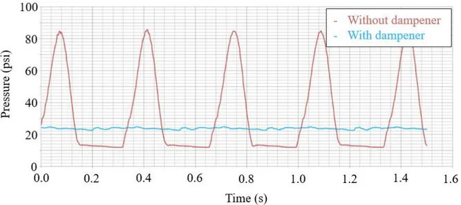
Figure 17 - Pulsation dampening on a 1" air operated double diaphragm positive displacement
pump ... 36
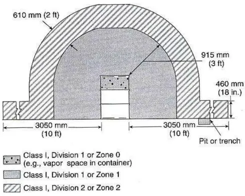
Figure 18 - Electrical area classification around an open container in a ventilated area ... 38
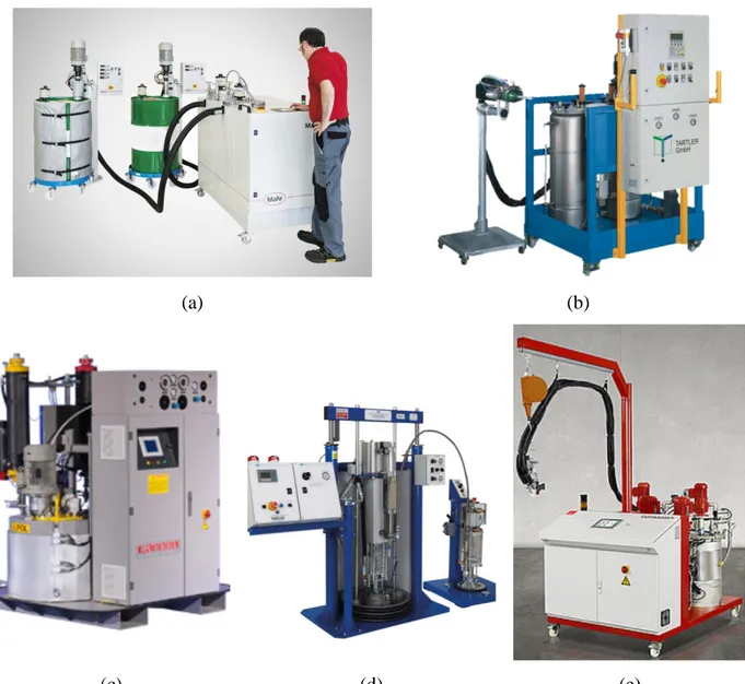
Figure 19 – Commercially available two-component metering and mixing system: (a) Mahr MarMax, (b) Tartler Nodopur, (c) Cannon B-System, (d) Meter Mix PAR200 and (e) DOPAG Compomix ... 40
Figure 20 - Kenics RL 180 static mixer ... 47
Figure 21 – Pumps used during testing: (a) Resin injection piston, (b) laboratory scale syringe pump, and (c) peristaltic pump ... 48
Figure 22 - Perkin Elmer UATR Two ... 49
Figure 23 – (a) FTIR sample positions and (b) mixing jar ... 50
Figure 24 - shaped sample collector: (a) Puller and (b) output of the static mixer into the V-shaped container ... 52
Figure 25 - Sampling positions within the V-shaped container to validate the performance of the static mixer ... 53
Figure 26 - Sampling positions within the V-shaped container using the static mixer and the peristaltic pump ... 53
Figure 27 - Overlay FTIR spectra of parts A and B ... 54
Figure 28 - Beer-Lambert law isocyanate absorbance peak height versus mix concentration ... 56
Figure 29 - FTIR spectra of samples mixed by hand for 2 minutes, data collected 1 hour after mixing ... 57
Figure 30 – Overlay FTIR spectra of hand mixed sample with parts A and B of the resin ... 58
Figure 31 – FTIR spectra evolution of a mixed sample over 48h ... 59
Figure 32 - Amplitude of the isocyanate absorbance peak at one and two hours after mixing ... 60
Figure 33 - FTIR spectra of samples mixed with the static mixer, data collected 1h after mixing 62 Figure 34 - Overlay of isocyanate absorbance peak height and pulsed flow rate model ... 65
Figure 35 – 1" Sanitary Stainless Steel Ball Valves: (a) amateur brewery application [101] and (b)
industrial food and pharmaceutical applications [102] ... 71
Figure 36 - Use of an intrinsic safety barrier for instrumentation located in a hazardous location The safety barrier, installed in the control panel, falls outside the hazardous location [103] 72 Figure 37 - In-line metering and mixing system process and instrumentation diagram: resin preparation, metering system and mixing and delivery areas ... 74
Figure 38 - Working principal of a plunger pump - Image courtesy of TKM LLC ... 78
Figure 39 - Sanitary tri-clamp piping connection with PTFE gasket: (a) assembled [104] and (b) disassembled [105] ... 80
Figure 40 - Resin preparation 3D CAD ... 82
Figure 41 - Metering system 3D CAD ... 83
Figure 42 - Mixing and delivery 3D CAD ... 84
Figure 43 - HMI Screens: (a) Home, (b) Status, (c) Calibration, (d) Manual Mode, (e) Data Logging and (f) Alarms ... 88
Figure 44 – Metering system assembly ... 91
Figure 45 - Mixing and delivery system mock-up ... 92
Figure 46 – Control panel ... 93
Figure 47 - Coriolis flowmeter precision validation: (a) Experimental data with error bars for the individual measurements and (b) Average of experimental data with error bars representing the standard deviation for each flowrate ... 96
Figure 48 - Gear flowmeter precision validation: (a) Experimental data with error bars for the individual measurements and (b) Average of experimental data with error bars representing the standard deviation for each flowrate ... 97
Figure 49 - Validation of doctor boxes level control logic ... 100
Figure 50 - Flow rate dampening of part A of the metering system at 100 psig ... 102
Figure 52 - Part B (top) and Part A (bottom) acetone samples colour evolution following three clean-in-place flush procedures ... 105 Figure 53 - SMX mixer used in the final system ... 106 Figure 54 – System resin outlet to doctor box one at the partner’s facility: (a) Level sensor and
system output and (b) system in operation with the prepreg line ... 109 Figure 55 - SMC prepreg material manufactured using the new in-line metering and mixing system
at the partner's facility ... 110 Figure 56 - Doctor box individual control logic ... 122 Figure 57 - PID cases for metering system output control ... 123
LIST OF APPENDICES
Appendix A – Chemical compatibility ... 121 Appendix B – Doctor box level control logic ... 122
CHAPTER 1
INTRODUCTION
To address climate change, Canada set an aim to reduce its greenhouse gas emissions by 30% by 2030 compared to current predictions [1]. Of the current emissions, the transportation industry is responsible for almost a quarter [2]. In fact, the Passenger Automobile and Light Truck Greenhouse Gas Emission Regulations, from the Canadian Environmental Protection Act, forces car manufacturers to find new solutions to reduce the fuel consumption of their vehicles [3]. Throughout its complete lifecycle, a vehicle’s useful life accounts for up to 80% of its total environmental footprint and among this impact, the vehicle’s mass has the most direct effect [4]. Recently, this industry has turned to the use of composite materials for structural applications. The use of such materials is mainly aimed at reducing weight when compared to traditional metallic materials. Consequently, these advanced materials provide a significant reduction in the emission of greenhouse gases throughout the useful life of the part and as a result, predictions suggest that more than one-third of global production of carbon-reinforced composites will be made by the automotive industry by 2021 [5]. To compensate for this higher demand, the development of rapid and low-cost manufacturing methods for composite materials is essential.
The high-performance composite materials used for load-bearing applications are generally formed of a high-temperature thermosetting matrix reinforced with high strength fibres. A common example is the combination of a vinyl ester resin matrix with a carbon fibre reinforcement [6]. Sheet Molding Compound (SMC) is a composite material that is best suited to manufacture large parts at high production volumes [7]. In fact, Magna International (Magna) and Ford Motor Co. are currently in the validation phase of a carbon fibre reinforced polymer front subframe manufactured using this material [8]. SMC is composed of a fast cure resin, short fibres reinforcement, fillers and a pre-mixed catalyst (hardener). This mixture, ready for hot compression moulding, is in the form of sheets and can be stacked at various thicknesses and put into a mould. To improve the applicability of these materials, additives (or fillers) are mixed with the resin. The type and amount of additives can influence several properties of the resin like reducing gas permeability, improve solvent resistance, increase mechanical and thermal properties and improve flame retardancy. With these multiple additives, automotive companies wishing to remain competitive must have a machine that allows the mixture of this resin with its multiple additives and allow the delivery to the production line continuously. Resin mixing systems play an important
role in the fabrication of composite parts and can range from the simple open top container with manual batch mixing, to the fully automated in-line resin mixing system that allows for continuously mixed resin dispensing. Ultimately, no matter the system used for the mixing process, resin homogeneity must be very high for manufacturers to get consistency in their products’ properties.
The use of composites for structural parts in the automotive industry is now of interest for mass market production cars. Many companies are in search of a resin mixing system that is versatile and robust enough to allow for the development and optimization of these new materials. Systems readily available do not offer enough versatility to adapt to new resin formulations. Resin properties are adjusted by modifying the manufacturing process parameters, mixing ratio of the various chemical components and adding additives to the resin. Unfortunately, these changes often alter the physical characteristics of the resin, requiring a versatile mixing system that performs well with a wide range of fluid viscosities and chemical compatibility. Currently available metering and mixing systems do not allow to process abrasive fluids in a Class 1 Division 1 hazardous location, limiting the manufacturers’ room for development and improvement. Likewise, the systems generally work in batches, making it difficult to manufacture the material continuously, a major drawback when high production output is the required.
To address these issues, Magna Exteriors Inc. (Magna), a division of Magna International Inc., worked jointly with the Centre technologique en aérospatiale (CTA) and Polytechnique Montréal on a research project. The objective was to develop a new and tailored in-line resin metering and mixing system to address the commercially available systems’ problems. The project team has great knowledge on system design, resin chemistry, composite manufacturing processes and project management, four important assets to the success of such an undertaking.
This thesis presents the results of the project and is divided into five (5) chapters. The first chapter goes over background information on composites in the automotive industry, mixers, pumps and resin mixing systems to put the reader in context. The second chapter demonstrates the performance of using a static mixer to obtain a homogeneous resin sample. Then, chapter three presents the development and assembly of the new automated in-line metering and mixing system. The fourth chapter is on the validation of the new system’s performance. Finally, the last chapter
draws conclusions and traces the path for future research work along with various recommendations.
CHAPTER 2
LITERATURE REVIEW
2.1 Composite materials in the automotive industry
Composite materials, or simply composites, are mostly known for their excellent mechanical properties. They are an assembly of two or more immiscible components with different properties that, when combined, create a material with usually better mechanical properties and lower weight than traditional metals. These high-performance materials, already used extensively for trim parts of niche vehicles1 in the automotive industry, have made little to no appearance in high production volume cars as of now, especially for structural parts [9], [10].
There is no proper definition for what a high production volume car is. Sales number vary greatly depending on the country, year and car model. Looking at the statistics of various popular cars of today’s industry, high-volume production vehicles sell somewhere in the mid to high hundreds of thousands of units per year. For example, Ford Motor Co. sells about 200,000 Focus and 900,000 F-series per year in the U.S. alone [11]. In a production perspective, considering a high-volume vehicle to sell on average 300,000 units per year with three 8 hour shifts per day, this means that original equipment manufacturers (OEMs) target part cycle times of 1 to 2 minutes. The manufacturing cost of composites is the main challenge the industry must overcome to implement these new materials to the production lines. Automakers must find ways to simplify and automate the production cycle to bring the cost down for structural composite materials to compete with traditional metals [10].
Composites are made of a matrix and a reinforcement. The fundamental role of the reinforcement is to carry the mechanical loads and to increase the mechanical properties of the matrix. In the automotive industry, fibre reinforcements are mostly made of glass or carbon in the form of chopped fibres, filament yarns and fabric.
On a mechanical level, the matrix is made of a polymer, multiple additives and a catalyst that binds the reinforcement and transfer the load between the fibres as well as protect them from the environment. On a physical level, the matrix gives the component shape and has an impact on the
quality of the surface finish. Matrices come in three main categories: polymer, ceramic or metallic. The use of polymer matrices is most common because of their lower processing temperature when compared to ceramic or metallic matrices and therefore allow for simpler tooling. Polymeric matrices are then subdivided into two categories: thermosets and thermoplastics.
A thermoset resin is a polymer that, through polymerization, exhibits a modification of its molecular chain called crosslinking. This chemical change results in a three-dimensional network of bonds. Advantages of thermoset matrices over thermoplastics include low processing temperatures and viscosity, liquid state at room temperature and excellent mechanical resistance. However, they cannot be recycled due to the chemical reaction they exhibit during cure. On the other hand, thermoplastics can be melted and reshaped if heated above a certain temperature. In addition, they have the advantage of having high impact resistance but have a characteristic high processing viscosities and show low heat resistance when compared to thermosets [12].
2.2 Manufacturing processes
Depending on a part’s geometry, application and production volume, different composite manufacturing processes are employed. In most high production volume parts, hot compression moulding using sheet moulding compound (SMC) is used. SMC combines short chopped fibres pre-impregnated with thermoset resins to produce a material in which only the concentration of the strengthening fibres is controlled but not their exact dimensions or orientation [6]. Figure 1 shows a typical SMC line from material manufacturing to hot compression moulding of the part.
Figure 1 - SMC material manufacturing process and hot compression moulding [13] The first step in manufacturing SMC is cutting the carbon fibre roving feed into small strands of approximately 25 mm. According to a study by Boylan et al., the SMC constituent that has the most influence on the required moulding force is reinforcement length. Results obtained show that the moulding force increases significantly over 25 mm. As a tradeoff between mechanical properties and material flow during moulding, the industry mostly uses reinforcement of 25 mm in length [14], [15]. These chopped fibres then fall onto a carrier film covered with a thin layer of resin. The resin is evenly spread onto the surface of the film using what is called a doctor box. These boxes collect the mixed resin at the output of the mixing system. Two resin covered films sandwich the chopped fibres before encountering a series of compaction rollers that compress the stack to impregnate the fibres with resin. Finally, depending on the resin chemistry, the produced
prepreg sheets are then stored for 24 to 48 hours to mature. During this time, the resin thickens and allows the sheets to be manipulated by a robot or an operator to be put in a heated mould. Finally, the material is compressed at high pressures of about 1,000 psi and the part cures in minutes to produce the final product [16].
Still allowing high production volumes, bulk moulding compound (BMC) is used in the same way as SMC but the material put in the compression mould, the charge, is in the form of a paste. During moulding, the charge is compressed and flows to fill the mould cavities. BMC parts tend to have lower mechanical resistance than SMC because the charge flow is harder to predict than with sheets that have already been stacked and positioned before moulding. In addition, the fibre length is shorter with BMC than SMC because the material paste requires significantly more flow to fill the mould cavities [17]. This makes BMC’s use limited to parts without significant load bearing applications [18].
Another manufacturing process that is currently used in production is high-pressure resin transfer moulding (HP-RTM). In this process, the resin is injected at high pressure in a closed mould where a dry composite preform is placed. Unfortunately, this manufacturing method is not suitable for high production volume because of the higher cycle time. More complex parts tend to be made using HP-RTM, while simple parts tend to use hot compression moulding methods like SMC.
Other composite materials and processes are used in the automotive industry but they do not meet the criteria for structural applications. For interior parts like dashboards, short fibre reinforced thermoplastic injection is used at high production volumes. This manufacturing method allows cycle time to drop below 90 seconds, making it perfect for high production volume. In addition, glass mat thermoplastics (GMT) is used for medium volume production and has become highly automated over the years. It can be compared to SMC in terms of manufacturing method but mechanical properties of the glass and thermoplastic combination do not meet structural requirements [19].
SMC compression moulding offers a lower cycle time and less expensive tooling and material costs than HP-RTM [20]–[22]. Nevertheless, HP-RTM is best suited for high performance and complex structural parts for low to medium volume production cars while SMC ideal for simpler structural parts for high production volume. Global Market Insights Inc. evaluated that
SMC hot compression moulding would soon dominate the automotive composite market as a manufacturing method. This growth is attributed to investment aimed at reducing cycle time, improving ease of manufacturing and offering competitive prices of the process. The same report predicts that the automotive composite market for structural applications will exhibit a compound annual gross rate of 7% until 2024 [10]. On a technical perspective, SMC technology seems to be in the best position to eliminate the industry’s dominant problems of cycle time and cost. Finally, this growing industry of high resistance structural parts is at the core of recent advancements in the automotive industry in the last decade.
2.3 Applications of composites in the automotive industry
Among the first production cars to make extensive use of composites was the 1953 Chevrolet Corvette. With its all-fibreglass exterior body, the Corvette had a production volume of only 300 cars during its introductory year. Since then, the Corvette has featured composite body parts and production has increased to an average of 36,250 cars per year for the latest generation [23], [24]. Yet, the Corvette’s composite body panels are not considered structural parts, as the car can still operate normally should they be removed or damaged.
Starting in 2013, the BMW i3 features an all-composite passenger cell, shown in Figure 2. The cabin is made from carbon fibre reinforced epoxy resin manufactured mostly through HP-RTM. The BMW i3 sold 31,482 vehicles globally in 2017 [25]. Yet, the BMW i3 is currently the largest composites serial production in the automotive industry, followed by BMW’s 7-series [26]. The 7-series uses a hybrid construction method for its cabin, also shown in Figure 2. The use of structural composites in the automotive industry can, therefore, be considered as limited to high performance or luxury cars with relatively low production volumes.
(a) (b)
Figure 2 – Use of structural composites in the automotive industry: (a) BMW i3's cabin made using HP-RTM [27] and (b) BMW’s 7-series hybrid-construction Carbon-Core [26]
Figure 3 shows SMC carbon fibre prototype parts intended for mass market vehicles. The picture on the left shows a front subframe manufactured by Magna. The subframe, a primary structural part supporting the motor and wheels, allows weight reduction by up to 34 percent and brings the number of parts from 45 to 6 when compared to the current mass produced metallic version [8]. The picture on the right shows an inner door panel manufactured in a partnership between HYM Haiyuan and Ranger Compositi using the same technology.
(a) (b)
Figure 3 – SMC use in the automotive industry: (a) SMC carbon fibre subframe and (b) inner door panel, JEC Show 2018
Like Magna, Magneti Marelli is currently developing a subframe made of SMC compression moulding. The subframe assembly, shown in Figure 4, is currently being tested on four-door compact sedan vehicles [28].
Figure 4 - SMC front subframe by Magneti Mirelli [29]
2.4 Thermoset resins, the importance of mix homogeneity and
characterization methods
The most commonly used matrices for structural applications in the automotive industry are epoxies and vinyl esters for their higher mechanical resistance and thermal performance [30], [31]. Vinyl ester polymers have been widely used for their good mechanical properties, thickening and curing performance as a matrix for SMC [32].
Vinyl ester polymers are a hybrid between polyester and epoxy polymers that feature two catalytic reactions. They are produced by the esterification of epoxy with carboxylic acid, usually bisphenol A and methacrylic acid. The prepolymer is usually dissolved in styrene to decrease the viscosity and to allow the reaction with the methacrylate [33].
In SMC applications, the resin is mixed with a thickening agent to allow the sheets to be manipulated and put into a mould. Physical and chemical thickening methods can be employed. Physical thickening uses crystalline resins but their research difficulty and cost limit their use [32]. In contrast, chemical thickening can be accomplished with isocyanates to form covalent bonds between the hydroxyl and carboxyl groups of the resin, known as urethane linkage [34].
For SMC manufacturing, the resin is made of two major components, part A (vinyl ester monomer, catalyst, inhibitor) and part B (isocyanate). The first reaction is a typical polyurethane reaction which involves isocyanate (Part B) reacting with amines in the vinyl ester resin (Part A)
to thicken the resin. This reaction increases the size of the molecules, notable via the thickening of the resin. This allows rolls of prepreg material to be manufactured and manipulated. The secondary reaction involves vinyl ester crosslinking for part manufacturing and is activated through heat when the product is moulded to its final shape. The increase in thermal energy makes the catalyst sufficiently reactive to initiate the crosslinking reaction of the vinyl ester. This final reaction is what gives the product its properties.
It is important to note that part B, containing mostly a mix of various forms of isocyanate, is very sensitive to humidity [34]. Moisture in the air, a polar compound, reacts with the isocyanate functional group and releases carbon dioxide as a product. This product is undesirable for a resin system because it can create porosity and decrease its mechanical properties. Therefore, during all the manufacturing phase, great care must be given to ensure the resin is stored in an airtight container in a dry environment.
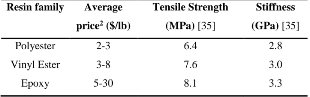
Vinyl ester’s mechanical properties and cost fall between polyesters and epoxies. Table 1 lists prices and tensile strength for polyester, vinyl ester and epoxy resin families.
Table 1 – Price and tensile strength comparison of polyester, vinyl ester and epoxy resins Resin family Average
price2 ($/lb) Tensile Strength (MPa) [35] Stiffness (GPa) [35] Polyester 2-3 6.4 2.8 Vinyl Ester 3-8 7.6 3.0 Epoxy 5-30 8.1 3.3
Mechanical properties of polyesters do not allow the resin to be used for structural applications. Even though epoxy resins have higher mechanical properties than vinyl ester resins, their higher cost may affect the business case viability in high production volumes. As seen above, BMW uses Huntsman’s Araldite LY 3585/Hardener XB 3458 epoxy system for its i3 passenger
2 Dubreuil, Personal discussion. 2018-10-04. Price listed are a rough estimate. Price will vary greatly depending on the desired properties and purchased volume. Price listed considers a high-volume purchase.
cell, but the car’s low production volume and high price, starting at 48,750 $ before taxes, makes it a niche model [36], [37]. In contrast, Magna uses vinyl ester resin for its prototype carbon fibre reinforced polymer front subframe in its development partnership with Ford [38]. The composite part, manufactured using SMC technology, is currently being tested on Ford Fusion models, a car that sold over 200,000 units in 2017 in the U.S. alone with a price starting at 22,838$, about half of BMW’s i3 [39], [40].
SMC part manufacturers add multiple additives and fillers to improve the resin properties and bring the cost down. Additives are used to improve performance and alter properties of the resin while fillers are mostly used to reduce cost. Figure 5 breaks down typical SMC resin formulations additive and filler weight content.
Figure 5 - Typical SMC resin formulations additive and filler content [17]
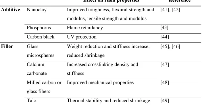
Filler content is much higher than additives, motivated by the economic advantage they offer. Table 2 lists common additives and fillers with their effect on resin properties.
Table 2 – Common additives and fillers and their effect on resin properties
Effect on resin properties Reference Additive Nanoclay Improved toughness, flexural strength and
modulus, tensile strength and modulus
[41], [42]
Phosphorus Flame retardancy [43]
Carbon black UV protection [44]
Filler Glass
microspheres
Weight reduction and stiffness increase, reduced shrinkage
[45], [46]
Calcium carbonate
Increased crosslinking density and stiffness
[47]
Milled carbon or glass fibers
Improved mechanical properties [48]
Talc Thermal stability and reduced shrinkage [49]
2.4.1 Mixing homogeneity
Two conditions are required for the polymer to reach the highest degree of polymerization; the components must be present in the right concentration and location [50], [51]. The first condition is dictated by the homogeneity of the mix while the second is a result of good dosage of the resin’s constituents. In process engineering, industrial mixing is the control of segregation and is used to obtain a homogeneous distribution of the components in the entire volume [52]. In the field of thermosetting polymers, because slight changes to the formulation can significantly affect the curing and properties of the resin, it is important to make sure that the homogeneity of the resin is sufficient and that the mixing process is well controlled [53].
Depending on the products to be mixed, a wide range of tests can be performed to evaluate homogeneity. Mix homogeneity is a statistical measure of the spatial dispersion of the components and is quantified using the coefficient of variation (CoV) of the products, also known as the intensity of segregation [54]. The CoV is the most commonly used metric to quantify the homogeneity of a mixture [55]. It is calculated by dividing the standard deviation 𝜎𝑐 by the mean
𝐶𝑜𝑉% = (𝜎𝐶
𝜇) ∗ 100 (1)
the standard deviation of the tested property is calculated by,
𝜎𝑐 = √1
𝑁∑(𝐶𝑖 − 𝜇)2
𝑁 𝑖=1
(2)
where 𝐶𝑖 represents the chosen numerical index, 𝜇 is the average of the index’s data set and 𝑁 is
the sample size, by the mean. In other terms, the coefficient of variation is a measure of the dispersion of a data set to the mean, or in this case, how equal are the component concentrations in the polymer. The index used for CoV calculations should be associated with the mixture, characterize the final stage of the mixture, be independent of the mixing method and easily determined [56]. The technique used to obtain the index will depend on the materials to be mixed and their properties.
In most industrial processes, a product with a CoV of less than 5% (or. 0.05) is considered adequately mixed [57], [58]. In other terms, a CoV of 0.05 means that the product is 95% homogeneous. For example, a CoV limit of 0.05 is also required by the Canadian Food Inspection Agency for dilute drug mixing processes in the food industry for animals [59].
2.4.1.1 Determination of the index used for CoV calculations
Infrared (IR) spectroscopy is by far one of the most versatile technique to characterize organic compounds. This technique exposes a sample of material to an infrared radiation. The energy absorption of the material with respect to the infrared wavelength is derived and can be related to the substance’s chemical functional groups. The machine expresses the results as absorbance or transmittance spectra, both of which are related using,
𝐴 = −log (𝑇) (3)
where A and T are respectively the substance’s infrared absorbance and transmittance at a given wavenumber. More details on the working principle of FTIR can be found in reference [60]. This test method can be used for quantitative monitoring of chemical reactions as well as sample
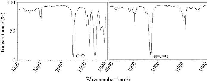
homogeneity [61]–[64]. More specifically, Fourier Transform Mid-Infrared Spectroscopy (FTmIR), analyzing a sample at wavenumbers from 4000 to 1000 cm−1, is best suited for organic polymers like isocyanate thickened vinyl ester resins and allows the detection of important functional groups. Figure 6 presents the FTIR transmittance spectra of polyvinyl acetate and methyl isocyanate. Polyvinyl acetate has a chemical composition that is very similar to vinyl ester resin.
Figure 6 – FTIR transmittance spectra of polyvinyl acetate (left) and methyl isocyanate (right)
[65]
Figure 6 shows the characteristic peak of the carbonyl group and isocyanate at 1738 cm-1
and 2810 cm-1 respectively. In the event of mixing both components together, as would be the case
in SMC manufacturing, mostly the same absorbance peaks would be observed in the new spectrum unless rapid chemical reactions occur and modify the composition of the sample. Then, depending on the mixing ratio of both components, the spectrum of one of the components would dominate. In SMC, the chemical thickening agent is added in very low quantity to the resin [66]. This suggests the spectrum of the mixed sample will closely resemble the one for vinyl ester resin with the addition of the major absorbance peaks of the isocyanate infrared spectrum in diminished amplitude.
To use FTIR data to quantitatively evaluate the mixing homogeneity, the Beer-Lambert law is used. The law is expressed as,
where 𝐴 is the absorbance, 𝜀 is the molar extinction coefficient, 𝑙 is the light path length and 𝑐 is the concentration, states that the FTIR absorbance of a functional group is proportional to its concentration in the sample [63].
This means the height of a characteristic peak on an FTIR absorbance spectrum graph can be measured and used for quantitative analysis to obtain the coefficient of variation between multiple samples. Figure 7 visually presents the Beer-Lambert law using the linearity of the correlation between FTIR absorbance and the concentration of aspirin dissolved in chloroform.
Figure 7 - FTIR calibration graph for aspirin dissolved in chloroform [63]
Applying this correlation to vinyl ester resin and isocyanate, the absorbance peak height of isocyanate at 2810 cm-1 can be measured and compared between multiple samples to determine the homogeneity of parts A and B of the resin. The result is expressed using the coefficient of variation (CoV).
Unfortunately, the Beer-Lambert law is only applicable under certain conditions. Non-linearities can be caused if the concentration is too high, if the sample contains solids that scatter the light or if the sample is fluorescent or phosphorescent. SMC vinyl-ester resin systems usually contain solid fillers and additives that could potentially make the Beer-Lambert law inapplicable.
Luckily, the resin does not contain conjugated double-bond systems which suggest it is not fluorescent.
Polymers mix homogeneity can also be evaluated by the mechanical property variations of the cured state. For thermoset polymers, mechanical properties can be directly correlated to the resin/hardener ratio [67]. Therefore, if the mixing is not homogeneous, specimens will show variance in their mechanical properties. On a microscopic scale, badly mixed samples will present areas with a higher or lower concentration of hardener, thus influencing the consistency of the results obtained from mechanical testing. Unfortunately, the test’s macroscopic scale does not inform about the intensity of segregation of the products.
A widely spread analytical technique for the characterization of thermosetting materials is differential scanning calorimetry (DSC). DSC essentially measures the energy required to change the temperature of the sample. Usually, this test allows the determination of glass transition and melting temperatures of a polymer compound. Studies have shown the dependence of the glass transition temperature on the composition of a sample [68]. Therefore, DSC analysis results can be compared to a reference sample to evaluate the variance in the mixing ratio. Unfortunately, DSC testing is a relatively slow and expensive test to perform and evaluating the homogeneity of a sample requires a modestly sized sample population to draw meaningful conclusions.
TGA measures the weight loss of a sample as a function of temperature. Applied to thermosetting polymers, this means that TGA testing records the change in mass due to the nature of the matter, monitoring the volatile and solid components. In a similar way to DSC, TGA test results can be used to evaluate the homogeneity of the sample as a different hardener to resin ratio will influence the cure reaction and consequently the weight loss behaviour of the sample. As with mechanical testing, TGA results do not explicitly allow quantifying the concentration of the products.
Other techniques using electrical property measurements can be used to evaluate the mix homogeneity of a two-component product. Unfortunately, it is hard to link the electrical properties of the polymer to its mixing ratio and draw meaningful conclusions because limited information is available on this characterization technique.
Finally, optical tests like spectrophotometry can be used when both components have different colours. For example, Figure 8 shows the homogeneity of two mixed fluids through a
static mixer. The colour difference between the two fluids allows for optical inspection to be used. Spectrophotometers can be used to obtain the red-green-blue (RGB) colour coordinates of a sample and compute the coefficient of variation [69].
Figure 8 - Visual evaluation of the homogeneity of a two-component product mix through a static mixer [70]
Of all testing methods discussed, FTIR spectroscopy is the most suitable for the project because of its versatility and widespread use for chemical characterization of organic compounds. Table 3 lists the advantages and disadvantages and of the reviewed characterization methods.
Table 3 - Advantages and disadvantages of mix homogeneity characterization methods Characterization
method
Advantages Disadvantages
FTIR Spectroscopy • Versatile and widely used to characterize chemical compounds • The data obtained can be linked to
the concentration of the samples and homogeneity
• Usually employed as a qualitative characterization method
Mechanical testing • Equipment easily accessible • It is hard to derive the relations between the mechanical properties of a sample to the homogeneity (intensity of segregation) DSC • Results are precise and can be
linked to the resin to hardener ratio
• Testing is relatively slow and expensive to perform TGA • Results can be linked to the resin
to hardener ratio
• It is hard to derive the relations between the TGA results of a sample to the homogeneity (intensity of segregation)
Electrical testing • N/A • Cannot be applied to all
substances and results cannot be explicitly linked to the mixing ratio and homogeneity of a sample Spectrophotometry • Results can directly be associated
with the homogeneity of a sample
• Only applies to samples that show colour differences between the components
2.5 Mixing technologies for in-line mixing systems
There are three broad categories for industrial in-line mixing devices: static, dynamic and impingement. Depending on the application and the products, different mixing technologies offer different advantages. The following literature review will focus on static mixers as they are used extensively in the polymer industry [71]. Dynamic and impingement mixing technologies will also be briefly reviewed.
2.5.1 Static mixing
Static mixers are simple mixing devices and consist of blades positioned in-line within a tube where the fluids to be mixed are forced trough. There are no moving parts and the mixing process relies mainly on splitting the flow multiple times. Static mixers do not require an external energy source to operate in the sense that no electrical, hydraulic or pneumatic motor is attached to the mixer. Instead, the energy required to mix both components is drawn from the fluid itself, resulting in a pressure drop across the equipment. A wide variety of mixer geometries are developed for different applications but their working principle remains the same: splitting and/or twisting the flow to produce a multitude of layers [72]. Table 4 below lists the three (3) most used static mixers for industrial processes [73].
Table 4 – Popular types of static mixers
Type/Name 3D model [73]
Kenics (twisted blades)
SMX (Static Mixer using crossbars X)
LPD (Low Pressure Drop)
The Kenics mixer consists of a series of right and left-twisted plates, positioned so that each leading edge is at 90 degrees offset to the trailing edge of the previous element.
The SMX mixer is built of small stacked lamellae positioned in an X shaped formation. Each lamellae stage is rotated by 90 degrees compared to the previous stage. These mixers come in multiple lamella configurations denoted by n, NP, NX and θ which respectively represent the
number of lamellae over the height of the channel, the number of parallel lamella along the length of one element, the number of lamella over the width of the channel, and the angle between the lamella. The standard SMX mixer is (2, 3, 8, 90°) as shown in Figure 9 [74].
Figure 9 - SMX mixer geometrical configuration (n, NP, NX, θ) = (3, 5, 9, 90°)
The LPD mixer is made of a series of semi-elliptical plates positioned at a 90-degree plane to plane offset from one another. Each mixing stage is also rotated by 90 degrees along the pipe axis.
2.5.1.1 Static mixer performance
Many research groups investigated the performance of static mixers using computational fluid dynamics. Among these groups, the most important contributions were performed by Rauline et al. and Meijer et al.
Rauline et al. made a quantitative analysis of the performance of six static mixer geometries including the Kenics, SMX (2, 3, 8, 90°), and LPD by computing the velocity field of the three-dimensional flow using POLY3DTM [54]. The analysis compared the mixers on many metrics that are considered to have an influence on mix homogeneity. The most significant analysis metrics are pressure drop, mean shear rate, interfacial stretching and intensity of segregation. The analysis was performed numerically. Results compared to the literature showed good agreement. A summary of the results obtained by Rauline et al. is presented in Table 5 for the Kenics, LPD and SMX mixers.
Table 5 - Mixing performance analysis of static mixers ΔP (MPa) Mean shear rate (s-1) Interfacial stretching Intensity of segregation Kenics 0.71 10 0.57 0.57 LPD 0.75 8.8 0.54 0.60 SMX 1.8 21 4.2 0.13
The pressure drop is the differential pressure between the inlet and outlet of a three-element mixer. Higher pressure drop can be problematic for high flow and high viscosity applications. In addition, as the pressure drop is the static mixer’s energy source, it must be considered for efficiency analysis. The mean shear rate measures the mixers’ ability to shear or “work” the fluid. Higher shear indicates better performance. Interfacial stretching is the length stretch ratio of a fluid element over a time t. A higher interfacial stretching means a greater contact area between the liquids to be mixed [75]. Finally, the intensity of segregation is the spatial distribution of the phases in the sample. For a chemical mixing application in the polymer industry, this metric is significantly important as having an excellent spread of the chemical functional groups ensures the highest degree of the cure can be reached. Results show that the SMX mixer offers the best performance as it shows the lowest intensity of segregation with the higher shear rate and interfacial stretching. However, the ratio of shear rate to pressure drop, which can be used to quantify the efficiency of the mixer because the pressure drop is directly related to the shear rate since the power is lost to friction, shows the Kenics is more efficient.
Moreover, the team developed empirical relations for the pressure drop as a function of mixer length. This allowed them to conclude that the SMX mixer was the most efficient if space is limited to mix the products.
Meijer et al. made computational fluid dynamics flow simulations of the most popular static mixers as a function of the number of mixing elements [73]. Flow simulations of a two-component flow are shown in Figure 10. Each row represents a different mixer geometry while each column shows the cross section of the mixer after various numbers of mixing elements (Nelem). Column 1
is a cross-section of the mixer at the fluid entrance where both fluids are clearly visible in black and white with no mixing performed yet. The following columns are the cross sections after 1, 2, 3, 4 and 8 mixing elements.
Figure 10 - Mixing profiles and layers as a function of the number of mixing elements [73] Visually comparing the mixing profiles after eight (8) mixing elements, the SMX mixing profile is more chaotic compared to the Kenics and LPD. Small aggregation areas can be seen on the outer edge of the SMX mixing profile at this stage while the Kenics shows a more predictable and organized mixing pattern. These results correlate with the intensity of segregation presented in Table 5 by Rauline et al. Overall, Meijer et al. also conclude that higher mixing homogeneity can be achieved using the SMX static mixer.
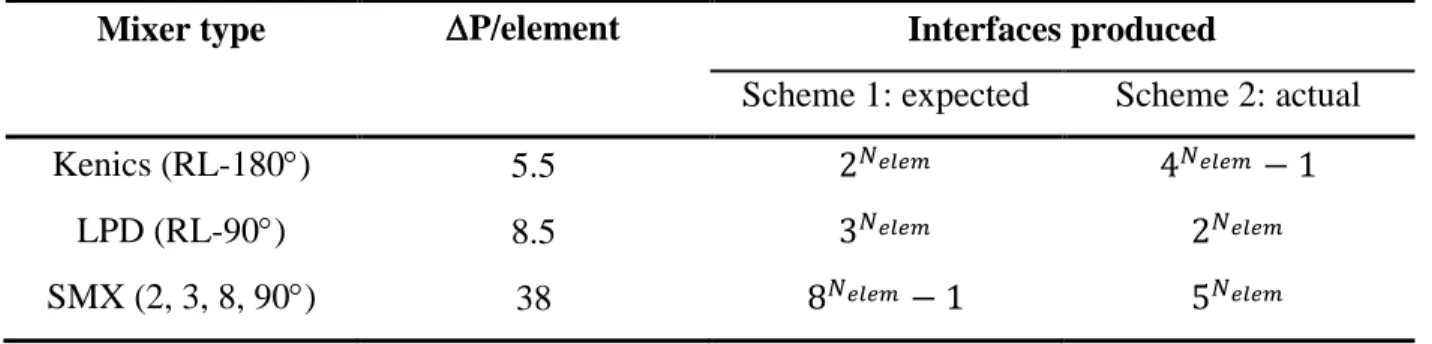
Meijer et al. also qualitatively investigated the number of interfaces produced by the mixers. The higher the number of interfaces produced, the more effective the mixer is at ensuring maximum contact area between the constituents. Results are expressed using two schemes in Table 6. Scheme 1 is based on geometrical analysis while scheme 2 is based on actual interface stretching from their simulations and it refers to what is observed in Figure 10. The group found that the mixing profiles of most mixers do not behave as predicted. For instance, the (1, 1, 3) SMX mixer, with its two mirrored crossing blades, causes two counter-rotating vortices that split the fluid to create two interfaces each of length equal to the diameter D of the mixer. This observation depends on the mixer geometry. This alters the mathematical expression that described the number of interfaces produces by each mixing element. Table 6 also lists the dimensionless pressure drop per mixing element. It is defined as the pressure drop through the mixer divided by the pressure drop in an empty pipe of the same diameter as the mixing elements.
Table 6 – Pressure drop and interfacial stretch of different static mixers
Mixer type P/element Interfaces produced
Scheme 1: expected Scheme 2: actual
Kenics (RL-180) 5.5 2𝑁𝑒𝑙𝑒𝑚 4𝑁𝑒𝑙𝑒𝑚 − 1
LPD (RL-90) 8.5 3𝑁𝑒𝑙𝑒𝑚 2𝑁𝑒𝑙𝑒𝑚
SMX (2, 3, 8, 90) 38 8𝑁𝑒𝑙𝑒𝑚 − 1 5𝑁𝑒𝑙𝑒𝑚
Results show the SMX mixer’s higher efficiency at interfacial stretching, a result of the number of fluid interfaces produced. After 8 mixing elements, the number of interfaces produced would be 390,625 for the standard SMX (2, 3, 8, 90) mixer against 65,535 for the Kenics (RL-180). For visual interpretation, actual interfacial stretch (Scheme 2) is plotted as a function of the number of mixing elements in Figure 11.
Figure 11 – Actual interfaces produced (Scheme 2) per mixing element
Overall, the literature shows that the SMX mixer is more efficient. However, this comes with the drawback of significantly higher pressure drop. Therefore, the SMX mixers should be used when space is limited and system pressure drop limitations are low. Nevertheless, it should
be kept in mind that high shear may be desirable for mixing but may be undesirable with shear sensitive fluids.
2.5.1.2 Identification of ideal mixer geometry and sizing
Although a lot of research has been done to evaluate the performance of static mixers, mixing homogeneity results will vary depending on multiple factors, the most important being the volumetric and viscosity ratios of the components. High volumetric ratios, usually considered 100:1 or above, require more mixing elements to minimize the intensity of segregation [76]. Likewise, the higher the viscosity ratio, the higher the difference in interfacial stretch between the components, resulting in residual shear stress at the interface that prevents the fluids to mix [77]. Vinyl ester resins used with isocyanate thickening agents have a volumetric and viscosity ratio of approximately 10:1 [78], [79]. A high viscosity ratio is generally considered as anything above 100:1 [76]. This means that vinyl ester and isocyanate is not considered easy nor exceptionally hard to mix.
Ultimately, choosing the ideal mixer geometry and size is what will result in the best trade-off between a maximized mix homogeneity and a minimized pressure drop. It is possible to perform computational fluid dynamic (CFD) analysis using a mixer geometry to simulate the way both fluids will mix. However, this type of analysis is complex and hard to execute with accuracy [80]. Using the literature and empirical data from static mixer manufacturer, the right mixer can be identified, provided that the fluids’ properties and application conditions are known. From there, experimental testing and mixer size iterations can allow improving the mixer. However, in most cases, simply adding mixing elements suffices to meet the process criteria.
Static mixers are usually available in reusable and disposable versions [70]. The disposable versions are an interesting solution with polymers. At the end of a manufacturing cycle, the mixer can simply be replaced instead of cleaned, reducing maintenance time and costs.
2.5.2 Dynamic mixing
Dynamic mixers consist of mixing elements that are mechanically agitated by an external power source. In its simplest form, a dynamic mixer can comprise of a shaft and blades submerged in a liquid. One common example is a regular household food processor or blender. In these instances, the mixer works in batches, meaning that one fixed and limited volume of fluid is mixed
at a time. This contrasts with the static mixer where the fluid is mixed continuously as it flows through. This can be a major drawback for an industrial process when large quantities of liquid must be mixed just-in-time for production. Also, this becomes especially critical with reacting polymers because the resin and hardener can react quickly, leaving little leftover time to manufacture the part.
Dynamic mixers are also offered in in-line versions, allowing continuous mixing. Figure 12 shows an in-line dynamic mixer with a two-component flow at the input (lower left) and the mixed output (top) [81]. The energy required for the mechanical agitation of the blades is provided by the electric motor (right). The added mechanical energy provided by the motor will result in less pressure drop when compared to static mixers.
Figure 12 – In-line dynamic mixer by Silverson [81]
Hybrids between static and dynamic mixers are also available. Figure 13 presents two similar static-dynamic mixing heads. Both examples are handheld devices with a motor at the back and a disposable mixing chamber at the output. The term static-dynamic comes from the fact that the blades inside the static mixer are dynamically agitated by an external motor. These mixers are designed to take advantage of the simplicity and easy maintenance of in-line static mixers while adding the energy of the motor-driven mixing blades. In this design, the components to be mixed only meet in the disposable plastic mixer. This eases maintenance cost and complexity by requiring only a change of mixing chamber.
(a) (b)
Figure 13 – Static-Dynamic mixing heads: (a) Static-Dynamic by DOPAG [82] and (b) LC 5/3 by Tartler [83]
One significant drawback of dynamic mixers is the inherently more complex design of the assembly. The addition of moving parts, external motor and energy supply (air, electricity, hydraulics, etc.) and weight make these mixers sometimes a little too complex for certain applications. Even though the addition of a mechanical agitation generally helps to mix the products together, simpler static mixers have been shown to have the ability to adequately mix polymers. Choosing this technology results in higher purchasing and operating costs. Moreover, the moving parts usually make it less durable with abrasive fluids, a common reality with resins containing additives.
2.5.3 Impingement mixing
The last commonly used mixing technology in the field of polymers is called impingement mixing. Figure 14 shows a schematic of a typical impingement mixing head along with a simulation of the mixing chamber. In this process, the two fluids collide at high pressure into a mixing chamber, typically around 80 to 200 bars [84]. This technology was developed for the polyurethanes industry, where conventional valves and actuators were too slow, too hard to clean and required regular maintenance. The sudden pressure drops exhibited by the fluids when entering the mixing chamber creates a lot of turbulence and mixes both products rapidly.
(a) (b)
Figure 14 –Impingement mixer: (a) Schematic of a typical impingement mixing head and (b) Simulation of impingement mixing for a two-component fluid [85]
Although high pressure mixing heads reliably create an even product distribution, they require more complex equipment to supply high-pressure flow. For a mixing chamber with directly opposed jets, the transition to turbulent mixing, a requirement for consistent mix quality, occurs at Reynolds number over 140 [86]. In the case of viscous polymers, achieving such flow requires significant amounts of energy and hydraulic units must be used, complexifying the resin dosing system.
An advantage of the impingement over the dynamic mixer is that cleaning is simplified because there are no rotating parts. Some models include a piston that can push the leftover polymer through at the end of a mixing phase while others have a dedicated solvent inlet for automated cleaning. Impingement mixers are ideal with high flow application, or processes requiring a high number of mixing shots per day, with some mixing units allowing flow rates of up to 8000 ml/sec [87].
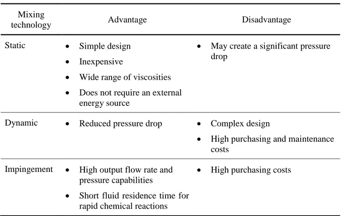
Table 7 presents a summary and comparison of static, dynamic and impingement mixers based on their respective advantages and disadvantages.
Table 7 - Comparison of static, dynamic and impingement mixers Mixing
technology Advantage Disadvantage
Static • Simple design • Inexpensive
• Wide range of viscosities • Does not require an external
energy source
• May create a significant pressure drop
Dynamic • Reduced pressure drop • Complex design
• High purchasing and maintenance costs
Impingement • High output flow rate and pressure capabilities
• Short fluid residence time for rapid chemical reactions
• High purchasing costs
Limited sources in the literature compare the various mixing technologies together [88].
The design criteria are more influencing the technology choice than the mix quality obtained with a specific technology. The literature shows that with all three technologies, very high homogeneity mixing can be achieved. Ultimately, cost, maintenance and applicability based on the fluids to be mixed will drive the technology choice.
2.6 Pumping technologies for in-line mixing systems
Equally important equipment of an industrial-grade mixing and dosing system are the pumps. This equipment dictates the precision at which both fluids will be injected into the mixing unit. Pump requirements for dosing and mixing systems include high repeatability, pulse-free, low shear, high pressure and abrasive and corrosive fluids capability.
Out of the many pump types that are currently available, all can be categorized into one of the two following groups: centrifugal pumps and positive displacement pump. Centrifugal pumps
![Figure 2 – Use of structural composites in the automotive industry: (a) BMW i3's cabin made using HP-RTM [27] and (b) BMW’s 7-series hybrid-construction Carbon-Core [26]](https://thumb-eu.123doks.com/thumbv2/123doknet/2341082.33879/27.918.116.808.106.310/figure-structural-composites-automotive-industry-series-construction-carbon.webp)