HAL Id: hal-02906767
https://hal.telecom-paris.fr/hal-02906767
Submitted on 25 Jul 2020
HAL is a multi-disciplinary open access
archive for the deposit and dissemination of
sci-entific research documents, whether they are
pub-lished or not. The documents may come from
L’archive ouverte pluridisciplinaire HAL, est
destinée au dépôt et à la diffusion de documents
scientifiques de niveau recherche, publiés ou non,
émanant des établissements d’enseignement et de
Communication Channel Parameters for QKD
Deployment GROUP SPECIFICATION
Romain Alléaume
To cite this version:
Romain Alléaume. Quantum Key Distribution (QKD); Device and Communication Channel
Param-eters for QKD Deployment GROUP SPECIFICATION. 2019. �hal-02906767�
ETSI GS QKD 012
V1.1.1
(2019-02)
Quantum Key Distribution (QKD);
Device and Communication Channel Parameters
for QKD Deployment
Disclaimer
The present document has been produced and approved by the Quantum Key Distribution (QKD) ETSI Industry Specification Group (ISG) and represents the views of those members who participated in this ISG.
It does not necessarily represent the views of the entire ETSI membership.
Reference
DGS/QKD-0012_DeployParam
Keywords
quantum cryptography, Quantum Key Distribution
ETSI
650 Route des Lucioles
F-06921 Sophia Antipolis Cedex - FRANCE Tel.: +33 4 92 94 42 00 Fax: +33 4 93 65 47 16
Siret N° 348 623 562 00017 - NAF 742 C Association à but non lucratif enregistrée à la
Sous-Préfecture de Grasse (06) N° 7803/88
Important notice
The present document can be downloaded from:
http://www.etsi.org/standards-search
The present document may be made available in electronic versions and/or in print. The content of any electronic and/or print versions of the present document shall not be modified without the prior written authorization of ETSI. In case of any
existing or perceived difference in contents between such versions and/or in print, the prevailing version of an ETSI deliverable is the one made publicly available in PDF format at www.etsi.org/deliver.
Users of the present document should be aware that the document may be subject to revision or change of status. Information on the current status of this and other ETSI documents is available at
https://portal.etsi.org/TB/ETSIDeliverableStatus.aspx
If you find errors in the present document, please send your comment to one of the following services:
https://portal.etsi.org/People/CommiteeSupportStaff.aspx
Copyright Notification
No part may be reproduced or utilized in any form or by any means, electronic or mechanical, including photocopying and microfilm except as authorized by written permission of ETSI.
The content of the PDF version shall not be modified without the written authorization of ETSI. The copyright and the foregoing restriction extend to reproduction in all media.
© ETSI 2019. All rights reserved.
DECTTM, PLUGTESTSTM, UMTSTM and the ETSI logo are trademarks of ETSI registered for the benefit of its Members.
Contents
Intellectual Property Rights ... 4
Foreword ... 4
Modal verbs terminology ... 4
1 Scope
... 5
2 References
... 5
2.1 Normative references ... 5
2.2 Informative references ... 5
3
Definition of terms, symbols and abbreviations ... 6
3.1 Terms ... 6
3.2 Symbols ... 8
3.3 Abbreviations ... 8
4
QKD Communication channels and architecture ... 8
4.1 QKD processes ... 8 4.2 QKD Communication channels ... 9 4.3 QKD Quantum channel ... 9 4.4 QKD Synchronization channel ... 10 4.5 QKD Distillation channel ... 10
5 QKD
architectures
... 10
5.1 Definition of QKD architecture ... 105.2 Dedicated quantum channel QKD deployment ... 10
5.2.1 Definition ... 10
5.2.2 Dedicated-link ... 11
5.2.3 Dedicated-to-quantum ... 11
5.3 Multiplexed QKD deployment architecture ... 12
5.3.1 Definition ... 12
5.3.2 QKD-only multiplexed architecture ... 12
5.3.3 Fully multiplexed architecture ... 13
6
Planning a QKD Deployment: Entities and Contexts ... 14
6.1 Entities and roles in deployment planning ... 14
6.2 Contexts ... 15
7
Information exchange templates ... 15
7.1 Introduction ... 15
7.2 Network parameters list and classification ... 16
7.3 QKD parameters list ... 17
Annex A (informative):
Authors & contributors ... 18
Intellectual Property Rights
Essential patents
IPRs essential or potentially essential to normative deliverables may have been declared to ETSI. The information pertaining to these essential IPRs, if any, is publicly available for ETSI members and non-members, and can be found in ETSI SR 000 314: "Intellectual Property Rights (IPRs); Essential, or potentially Essential, IPRs notified to ETSI in
respect of ETSI standards", which is available from the ETSI Secretariat. Latest updates are available on the ETSI Web
server (https://ipr.etsi.org/).
Pursuant to the ETSI IPR Policy, no investigation, including IPR searches, has been carried out by ETSI. No guarantee can be given as to the existence of other IPRs not referenced in ETSI SR 000 314 (or the updates on the ETSI Web server) which are, or may be, or may become, essential to the present document.
Trademarks
The present document may include trademarks and/or tradenames which are asserted and/or registered by their owners. ETSI claims no ownership of these except for any which are indicated as being the property of ETSI, and conveys no right to use or reproduce any trademark and/or tradename. Mention of those trademarks in the present document does not constitute an endorsement by ETSI of products, services or organizations associated with those trademarks.
Foreword
This Group Specification (GS) has been produced by ETSI Industry Specification Group (ISG) Group Quantum Key Distribution (QKD).
Modal verbs terminology
In the present document "shall", "shall not", "should", "should not", "may", "need not", "will", "will not", "can" and "cannot" are to be interpreted as described in clause 3.2 of the ETSI Drafting Rules (Verbal forms for the expression of provisions).
1 Scope
The present document describes the main communication resources involved in a QKD system and the possible architectures that can be adopted when performing a QKD deployment over an optical network infrastructure.
The scope of the present document is restricted to QKD deployments over fibre optical networks. Architectural options are also restricted to point-to-point communication.
The different entities that can take part in a QKD deployment and the possible contexts of deployment capturing the roles played by the different entities are defined. One specific context (context1) is then addressed where one entity (QKD_O), operating QKD Modules, plans a QKD deployment over an optical network infrastructure, operated by another entity (NET_O).
The information regarding the QKD system parameters and the network parameters to be exchanged (in context1) are listed and prioritized. The corresponding tables, placed at the end of the present document, can be used as a standard template for the exchange of information between QKD_O entities and NET_O entities involved in the QKD deployment.
2 References
2.1 Normative
references
References are either specific (identified by date of publication and/or edition number or version number) or
non-specific. For specific references, only the cited version applies. For non-specific references, the latest version of the referenced document (including any amendments) applies.
Referenced documents which are not found to be publicly available in the expected location might be found at
https://docbox.etsi.org/Reference/.
NOTE: While any hyperlinks included in this clause were valid at the time of publication, ETSI cannot guarantee their long term validity.
The following referenced documents are necessary for the application of the present document. Not applicable.
2.2 Informative
references
References are either specific (identified by date of publication and/or edition number or version number) or
non-specific. For specific references, only the cited version applies. For non-specific references, the latest version of the referenced document (including any amendments) applies.
NOTE: While any hyperlinks included in this clause were valid at the time of publication, ETSI cannot guarantee their long term validity.
The following referenced documents are not necessary for the application of the present document but they assist the user with regard to a particular subject area.
3
Definition of terms, symbols and abbreviations
3.1 Terms
For the purposes of the present document, the following terms apply:
channel: "logical channel", i.e. a communication link, between a sender and a receiver, over which some logical
information is exchanged
NOTE: Throughout the present document, the term "channel" refers by default to a "logical channel", i.e. a communication link, between a sender and a receiver, over which some logical information is exchanged. Depending on the context, the channel implementation, i.e. the physical nature of the channel, related to the physical encoding of the information, will also often be considered. In that case the name "channel" will refer to both the logical nature of the channel, and to the physical nature of its implementation.
classical optical channel: optical implementation of a communication channel for transmitting classical information
NOTE: Classical optical signals typically consist of optical pulses containing a large number of photons, over which some information is encoded (in time, phase, intensity, polarization, etc.). Classical optical signals are perfectly distinguishable and communication over a classical optical channel is therefore vulnerable to zero-error attacks where an eavesdropper non-destructively reads the signals, without introducing errors and yet fully copies the logical data.
context: "context of deployment", i.e. a scenario specifying some aspects of the roles played by the different entities,
and their interplay
disturbance on the quantum channel: disturbance on the quantum channel related to the noise on the QKD quantum
channel
NOTE: Disturbance is measured by evaluating the correlation level between the classical strings (raw data) shared by A and B after the quantum communication phase.
matching QKD module: QKD Module that when connected by appropriate communication channels can cooperate to
run a QKD protocol with the QKD Module it is matched with
NOTE: Typically a type A QKD Module could be a matching QKD Module for a type B QKD Module and vice versa where compatibility requirements are met.
network operator: entity in charge of operating technically the optical network infrastructure and in particular
providing communication interfaces to QKD at points A and B
EXAMPLE: In the context of a deployment, this role is typically assumed by a service provider.
QKD distillation channel: channel used to exchange digital classical information, typically between QKD Modules of
type A and B, in order to agree on a shared secret key starting from the raw data the QKD Modules initially obtain in an earlier stage of a quantum key distribution protocol
NOTE 1: The communication over the distillation channel is typically used to perform two stages of a QKD protocol:
Sifting: A and B communicate classical information to select a subset of the raw data, leading to the
sifted key.
Classical post-processing: A and B agree on a secret key from their respective raw data via public
discussion over the distillation channel.
NOTE 2: The QKD distillation channel can be implemented over different types of transmission media (optical, copper wire, etc.).
NOTE 3: The name "Distillation" normally refers to the notion of classical post-processing excluding sifting that can be performed prior to distillation. Nevertheless the name "distillation" is used as the name for this channel that can also include communications associated with sifting, since this name is non-ambiguous and expresses clearly the nature of the information exchanged on the channel. (Similarly the name "Synchronization channel" is used to refer to a channel that can convey information wider than time synchronization.)
NOTE 4: The QKD Distillation channel can also be called the "Distillation channel".
NOTE 5: One of the security requirements of QKD protocols is that the Distillation channel is authenticated. Discussing security and cryptographic requirements of QKD is outside of the scope of the present
document. Deployment and initialization of matched QKD modules should be done in accordance with an approved security policy.
QKD module: set of hardware and software components that implements QKD cryptographic functions and quantum
optical processes, including cryptographic algorithms and protocols and key generation, and is contained within a defined cryptographic boundary
NOTE: A QKD Module constitutes one endpoint in a QKD link. It can be of type A (sender) or B (receiver). A QKD Module typically has three communication channel interfaces:
QKD quantum channel,
QKD synchronization channel,
QKD distillation channel.
QKD operator: entity in charge of operating technically the QKD Modules
EXAMPLE: In the context of a deployment, the "QKD Operator" role would typically be the responsibility of the owner of the QKD Module. It might also be the responsibility of a tier (possibly the QKD manufacturer) in charge of QKD Module operation and maintenance.
QKD quantum channel: quantum optical channel, typically between QKD Modules of type A and B, used to perform
quantum key distribution
NOTE 1: It is implemented by sending quantum optical signals (typically weak coherent states of light), on which information is encoded (different encodings can be used: phase, polarization, time-bin, spatial mode, etc.). NOTE 2: In the context of the present document, it is assumed that the quantum channel is implemented over an
optical fibre.
NOTE 3: The QKD Quantum channel can also called "Quantum channel".
QKD synchronization channel: channel that carries reference signals for the purpose of reference frame sharing
(synchronisation, phase reference, polarization reference etc.), typically between QKD Modules of type A and B, in order to perform quantum key distribution
NOTE 1: It is typically implemented by encoding analogic information encoded over classical optical signals, sent over an optical fibre.
NOTE 2: The name "Synchronization" normally refers exclusively to the notion of time reference sharing and no other types of reference information. Nevertheless the name "Synchronization" is used as the name for this channel that can also include other types of reference information, since this name is non-ambiguous and expresses clearly the nature of the information exchanged on the channel. (Similarly the name "Distillation channel" is used to refer to a channel that can convey information wider than distillation.) NOTE 3: The QKD Synchronization channel can also be called the "Synchronization channel".
QKD system: system composed of a pair of matching QKD Modules (of type A and B)
NOTE: When properly connected to the appropriate communication channels a QKD system can perform quantum key distribution: establishment between A and B of a symmetric secure key.
Quantum Key Distribution (QKD): procedure or method for generating and distributing symmetrical cryptographic
quantum optical channel: optical implementation of a communication channel for transmitting quantum signals
NOTE: It is implemented by encoding quantum information, i.e. non-orthogonal quantum states, on dim optical pulses containing a low mean photon number. The optical link on which the quantum channel is implemented is in general required to be transparent, i.e. it cannot contain any amplifier elements.
raw data: raw correlated classical data at A and B that was shared using a quantum channel and after any sifting has
been implemented
NOTE 1: In many implementations quantum signals are prepared at A, sent on the quantum channel and then received and detected (with finite probability and fidelity) at B.
NOTE 2: The name "raw data" refers to more than one classical string, e.g. one at A and one at B. These raw strings are typically correlated but not identical.
3.2 Symbols
Void.
3.3 Abbreviations
For the purposes of the present document, the following abbreviations apply:
A Alice, designating either a QKD Module, or the operator of said device, or the location of said device
AES Advanced Encryption Standard
B Bob, designating either a QKD Module, or the operator of said device, or the location of said device
CV Continuous Variable DistilB Distillation channel interface of B
NET Network NET_O Network Operator PMD Polarization Mode Dispersion QKD Quantum Key Distribution
QKD_O Quantum Key Distribution Operator QKDA Quantum Key Distribution device of type A
QKDB Quantum Key Distribution device of type B
WDM Wavelength Division Multiplexing
4
QKD Communication channels and architecture
4.1 QKD
processes
A QKD system consists of two QKD Modules (QKDA and QKDB, in short A and B) connected by communication
channels (a Quantum channel, a Distillation channel and possibly a Synchronization channel). The two QKD Modules, connected by communication channels, follow a protocol that can be described as a set of processes, executed in parallel or sequentially to establish a symmetric secure key at both A and B.
A high-level list and description of the three main processes that are executed by a QKD system are provided in table 1, focusing on the communication needs associated with these three processes.
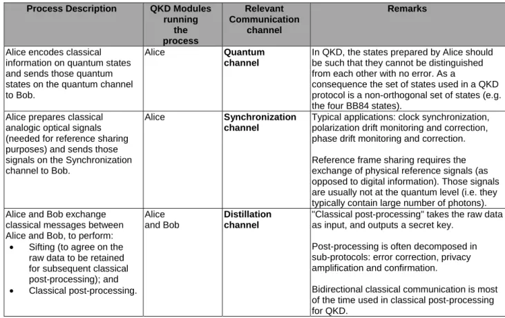
Table 1: Three typical main QKD processes
Process Description QKD Modules running the process Relevant Communication channel Remarks
Alice encodes classical information on quantum states and sends those quantum states on the quantum channel to Bob.
Alice Quantum
channel
In QKD, the states prepared by Alice should be such that they cannot be distinguished from each other with no error. As a
consequence the set of states used in a QKD protocol is a non-orthogonal set of states (e.g. the four BB84 states).
Alice prepares classical analogic optical signals (needed for reference sharing purposes) and sends those signals on the Synchronization channel to Bob.
Alice Synchronization
channel
Typical applications: clock synchronization, polarization drift monitoring and correction, phase drift monitoring and correction. Reference frame sharing requires the exchange of physical reference signals (as opposed to digital information). Those signals are usually not at the quantum level (i.e. they typically contain large number of photons). Alice and Bob exchange
classical messages between Alice and Bob, to perform:
• Sifting (to agree on the raw data to be retained for subsequent classical post-processing); and • Classical post-processing. Alice and Bob Distillation channel
"Classical post-processing" takes the raw data as input, and outputs a secret key.
Post-processing is often decomposed in sub-protocols: error correction, privacy amplification and confirmation.
Bidirectional classical communication is most of the time used in classical post-processing for QKD.
4.2
QKD Communication channels
As can be seen from table 1, a QKD system runs different processes locally at A / B and some processes require communication between A and B. These communications may occur on up to three different types of channels:
a) QKD Quantum channel.
b) QKD Synchronization channel (typically an analogic optical classical channel).
c) QKD Distillation channel (typically conventional bidirectional digital channel(s) - one or more depending on the implementation).
Some characteristics of these communication channels are described in clauses 4.3 to 4.5.
4.3 QKD
Quantum
channel
The Quantum channel is typically a unidirectional optical channel. This optical channel can be fibre-based or free-space. The Quantum channel is typically used in a QKD protocol, to send non-orthogonal quantum states, conveying classical information from A to B.
QKD protocols typically rely upon monitoring the disturbance (errors) when transmitting random classical data over the quantum channel. If the disturbance is too high the QKD system assumes the disturbance could be due to an adversary and is unable to distil secure keys. The level of disturbance below which secure keys can be distilled depends upon various protocol-specific security parameters. The ability to detect potential eavesdropping of the quantum signals in transit through the disturbance this would necessarily introduce is the unique proposition of QKD.
Quantum channel parameters, in particular optical losses and noise sources (such as optical attenuation, imperfect optical encoding at A, reference frame stability between A and B, imperfect detection at B, external optical signals, etc.), play a crucial role in determining the practicality of distributing secure keys using QKD. To a large extent, the ability to perform QKD over a given Quantum channel with fixed optical losses depends on the ability to minimize the end–to–end noise level.
4.4
QKD Synchronization channel
The Synchronization channel is typically used to exchange reference information between A and B, using classical signals (typically containing many photons each). Such information can in particular be used for:
• Clock synchronization.
• Phase reference sharing and compensation (in particular in CV-QKD).
• Polarization drift monitoring and compensation.
The Synchronization channel shall be implemented on an optical path whose propagation characteristics (duration, dispersion, polarization drift, etc.) are close to (or well correlated with) the propagation characteristics on the quantum channel. As a consequence, the Synchronization channel is often time-multiplexed with the Quantum channel, but other implementations are possible.
4.5
QKD Distillation channel
The Distillation channel is typically a conventional bidirectional optical digital channel, used to send classical
information from A to B or B to A. Bidirectional classical communications between A and B are typically necessary for sifting and post-processing, such as error correction and privacy amplification.
The QKD Distillation channel can be totally distinct physically from the Quantum channel and does not need to be optical. On the other hand, constraints on protocol performance can impose requirements on channel characteristics, such as throughput and latency.
5 QKD
architectures
5.1
Definition of QKD architecture
Deploying a QKD system requires allocation of network resources (communication channels) that are managed by a network operator (NET_O). As discussed in clause 4.2, the communication requirements of QKD can be categorized into 3 different groups: distillation, synchronization and quantum.
"QKD architectures" are the possible design choices that lead to specify how each communication requirement is accommodated.
The possible architectural choices are sorted according to the choice to multiplex (or not) over the same fibre the quantum and synchronization channels with the distillation channel that typically carries signals of much higher power. There are two variants, named Dedicated-link and Dedicated-to-quantum.
5.2
Dedicated quantum channel QKD deployment
5.2.1 Definition
Dedicated quantum channel QKD deployments correspond to architectures where QKD and Synchronization channels are deployed on a dedicated link.
Such architectures have the advantage of providing a good isolation for the QKD channel, against noise induced by the QKD Distillation channel (as well as other external classical channels). On the other hand, they require to allocate dark fibre in order to deploy the quantum communication channel(s).
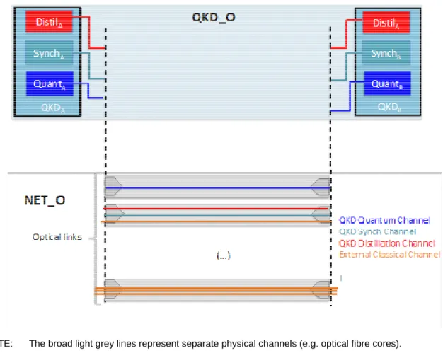
5.2.2 Dedicated-link
NOTE: The broad light grey lines represent separate physical channels (e.g. optical fibre cores). Figure 1: Dedicated-link architecture
In the Dedicated-link architecture, a dedicated link is allocated to QKD Quantum and QKD Synchronization channels. QKD Distillation and other channels are deployed on other links (see Figure 1).
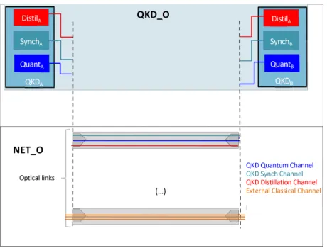
5.2.3 Dedicated-to-quantum
In the dedicated-to-quantum architecture, depicted in Figure 2, the Quantum channel is deployed on a dedicated link, while the Synchronization and Distillation channels (as well as some possible external optical channels) are deployed on another link.
Such an architecture can be motivated in some cases by the need to minimize the noise induced by the Synchronization channel on the Quantum channel. Deploying Synchronization and Quantum channels on distinct physical links is however not always possible. It requires in general that the physical drifts (such as propagation time, phase,
birefringence, dispersion, etc.) of the first link are correlated to the physical drifts that are estimated on the second link (based on pilot signals sent on the Synchronization channel).
DistilA QKD QuantumChannel QKD SynchChannel QKD Distillation Channel ExternalClassical Channel l Optical links NET _O QKD_O SynchA QKDA QKDB DistilA SynchB QuantB QuantA (…)
NOTE: The broad light grey lines represent separate physical channels (e.g. optical fibre cores). Figure 2: Dedicated-to-quantum architecture
5.3
Multiplexed QKD deployment architecture
5.3.1 Definition
Multiplexed QKD deployments correspond to architectures where QKD and Distillation channels (and possibly other external classical communication channels) are multiplexed on the same communication link.
Such architectures have the advantage of reducing the physical resources (e.g. optical fibre) required to implement the communication channels. On the other hand, multiplexed architectures introduce the need to efficiently filter out the noise induced by QKD Distillation or other multiplexed channels. It can also introduce additional losses due to additional devices in the fibre, e.g. multiplexers, splitters, etc.
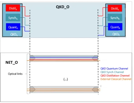
5.3.2
QKD-only multiplexed architecture
QKD-only multiplexed architecture stands for the channel allocation depicted in Figure 3, where the three QKD-related communication channels are multiplexed on a single link, while external classical channels are accommodated on physically different links.
In such an architecture, specific effort to multiplex the Distillation and Quantum channels is necessary, with the advantage that the distillation channel is controlled by QKD_O. Hence the parameters of the Distillation channel, including launch power, can be optimized by QKD_O, and brought significantly below 0 dBm, in order to minimize the noise on the Quantum channel, under the condition that the Distillation channel remains functional.
NOTE: The broad light grey lines represent separate physical channels (e.g. optical fibre cores). Figure 3: Architecture QKD-only multiplexed
5.3.3
Fully multiplexed architecture
Fully multiplexed architecture stands for the channel allocation depicted in Figure 4, where the three QKD-related communication channels as well as some external channels are multiplexed on a single link (for example different wavelengths in a single strand of optical fibre, as in WDM schemes).
In this architecture, the optical launch power of external classical channel is not controlled by the QKD operator, and QKD fully multiplexed architecture thus allows co-deployment of QKD and standard WDM communication on the same fibre. Conversely, the noise control procedures (in particular filtering of noise induced by classical external channels onto QKD channel, due to Raman scattering) are more demanding than in the QKD-only multiplexed architecture as they have to cope with external classical channel launch power around 0 dBm or more.
DistilA
QKD QuantumChannel
QKD Synch Channel QKD Distillation Channel ExternalClassical Channel l Optical links N ET_O QK D _O SynchA QKDA QKDB DistilA SynchB QuantB QuantA (…)
NOTE: The broad light grey lines represent separate physical channels (e.g. optical fibre cores). Figure 4: Fully multiplexed architecture
6
Planning a QKD Deployment: Entities and Contexts
6.1
Entities and roles in deployment planning
This clause describes the entities that can take part in a QKD deployment: QKD operator (QKD_O), Network operator (NET_O) and USER. The possible contexts of deployments, namely the "generic roles" played by QKD_O, NET_O and USER, are then described as well as how such roles determine the information to be that shall be exchanged. These definitions will are then be used in templates (clause 7), specifying the information to be exchanged when performing a QKD deployment over an optical network infrastructure.
QKD Operator (QKD_O)
QKD_O is the entity in charge of technical operations of the QKD Modules. QKD_O is allowed to access to the internal information stored within QKD Modules (such as Quantum channel estimated parameters, quantum bit error rate, status of key buffer, etc.). QKD_O has a knowledge of the QKD Module characteristics that is sufficient to be able to
estimate/plan the QKD performance (in terms of key rate) based on some knowledge about the communication channels.
Network Operator (NET_O)
NET_O is the entity in charge of technical operation of the optical network infrastructures and, in particular, communication channels. NET_O supervises network operation and allocates communication channels to different actors. In the context of a QKD deployment NET_O is in charge of providing some communication channels to QKD_O in order to accommodate the communication needs (Quantum, Synchronization, Distillation channels) of deployed QKD Modules. The knowledge NET_O has about network communication channel characteristics (loss, impairments, presence of amplifiers, etc.) and also about existing network traffic can be absolutely necessary or useful in order to estimate QKD performance and thus to plan successful QKD deployments.
DistilA
QKD Quantum Channel
QKD Synch Channel
QKD DistillationChannel
External ClassicalChannel l Optical links NET _O Q KD _O SynchA QKDA QKDB DistilA SynchB QuantB QuantA (…)
User (USER)
USER designates the system or the application that makes use of the key exchanged by QKD. USER can for example be an AES cipher application, with a given key renewal policy that depends on the traffic it encrypts. This will in turn influence the key demand. In general, the location and the application of USER influence the requirements on QKD-based key establishment. Information exchange between USER and QKD_O and possibly between USER and NET_O can be necessary to plan a deployment.
6.2 Contexts
A context or "context of deployment" is a scenario specifying some aspects of the roles played by the different entities, and their interplay.
Context1
The present document focuses on one context called Context1, where:
• The deployment is managed by QKD_O.
• USER and QKD_O are a common entity.
NOTE: The fact that USER and QKD_O are a common entity reduces the information that needs to be shared to plan a deployment, since the USER of the QKD-related services has all available knowledge of the network characteristics.
EXAMPLE: Example of scenario corresponding to Context1:
A QKD manufacturer that also manufactures Level 2 encryptors, wants to deploy QKD and Level 2 encrypted data over a dark fibre, operated by a telecom provider.
In this example, the QKD_O entity is the same as the USER entity.
The deployment is managed by QKD_O. As a consequence NET_O does not need
information about internal parameters of the QKD Modules (this reduces the information to be exchanged).
Finally, the deployment is performed over dark fibre, which also restricts the information QKD_O and NET_O have to exchange (see clause 5).
7 Information
exchange
templates
7.1 Introduction
Clause 7 considers that the deployment context is Context1 (defined above), where QKD_O and USER are the same entity that is in charge of planning the QKD deployment over an optical network infrastructure, operated by NET_O. The list of information (with priority levels) to be exchanged between a QKD Operator (QKD_O) and a Network Operator (NET_O) is specified in tables 2 and 3.
These tables may be used as a standard template for the exchange of information between QKD_O entities and NET_O entities involved in the QKD deployment.
Priorities are categorized from lowest (1) to highest (3) where:
• 3: information is necessary and shall be communicated.
• 2: information is useful and should be communicated.
The tables may be adapted where necessary for application in other contexts:
• The tables may be reformatted and items re-arranged.
• Necessary information (priority level 3) shall in general remain present.
• Priority levels should be kept identical.
• Additional information, with adapted priority level may be added.
7.2
Network parameters list and classification
This clause defines the network parameters that shall, should or may be specified by NET_O and communicated to the QKD_O entity when planning a QKD network deployment in Context1, where the QKD_O entity plans the entire deployment.
Table 2: Network parameters list and priority levels 3 / 2 / 1
indicating parameters that NET_O shall / should / may communicate to QKD_O
Channel(s) availability Priority Level
Availability & type of optical channel (Type of channel refers to dedicated fiber or
multiplexed fiber)for QKD Quantum channel? 3
If multiplexed, list of available & occupied channels & their characteristics 2
Availability of an optical channel for QKD Distillation channel? 3
List of potential fibre links through network 2
List of available optical channels on these fibre links 2
Basic Channel Parameters
Centre wavelength of channel 3
End–to–end path description and length of channel 3
Channel loss (attenuation) 3
Connector type(s) 2
Are any active components such as amplifiers present in the channel? 3
If Yes, options for bypassing such elements 2
Fibre specification (type, size, characteristics, etc.) 2
Polarization Mode Dispersion (PMD) 2
Is the channel on a dedicated dark fibre? (Applies to Quantum channel only) 2
If No, maximum optical power from other occupied channels that can be present at receiver end of the channel within the 'Range of accepted wavelengths' of the QKD Module (from the list of QKD parameters)
2 If No, maximum optical power from other occupied channels that can be present at
receiver end of the channel within the 'Range of accepted wavelengths' of the QKD Module (from the list of QKD parameters) after any possible reductions in classical power levels that could be made without disturbing the classical communications
2 If No, wavelength distribution, power and traffic directionality or other optical signals
multiplexed onto the same fibre 2
Wavelength bandwidth assumed for above channel loss (attenuation) 1
List of end-to-end cross-talks between this channel and each of the other channels
proposed for use by the QKD system(s) 1
Other Channel Parameters
Locations of any large losses within the network 1
Locations and specifications of filters within the channel 1
Access location(s) for QKDA and QKDB 1
Exceptional sources of instability or vibrations 1
Polarisation stability 1
What guarantees are provided for availability, reliability and noise 1
7.3
QKD parameters list
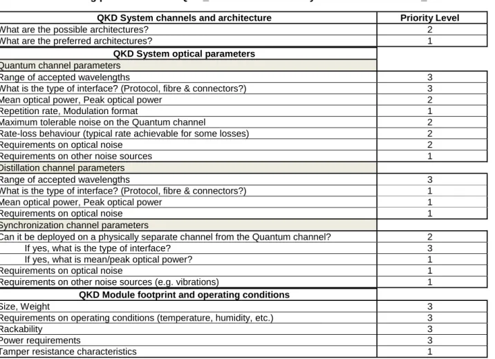
Table 3: QKD parameter list and priority levels 3 / 2 / 1
indicating parameters that QKD_O shall / should / may communicate to NET_O
QKD System channels and architecture Priority Level
What are the possible architectures? 2
What are the preferred architectures? 1
QKD System optical parameters
Quantum channel parameters
Range of accepted wavelengths 3
What is the type of interface? (Protocol, fibre & connectors?) 3
Mean optical power, Peak optical power 2
Repetition rate, Modulation format 1
Maximum tolerable noise on the Quantum channel 2
Rate-loss behaviour (typical rate achievable for some losses) 2
Requirements on optical noise 2
Requirements on other noise sources 1
Distillation channel parameters
Range of accepted wavelengths 3
What is the type of interface? (Protocol, fibre & connectors?) 1
Mean optical power, Peak optical power 1
Requirements on optical noise 1
Synchronization channel parameters
Can it be deployed on a physically separate channel from the Quantum channel? 2
If yes, what is the type of interface? 3
If yes, what is mean/peak optical power? 1
Requirements on optical noise 1
Requirements on other noise sources (e.g. vibrations) 1
QKD Module footprint and operating conditions
Size, Weight 3
Requirements on operating conditions (temperature, humidity, etc.) 3
Rackability 3
Power requirements 3
Annex A (informative):
Authors & contributors
The following people have contributed to the present document:
Rapporteur:
Romain Alléaume, Telecom ParisTech (IMT), France
Contributors:
Thomas Chapuran, Applied Communication Sciences, USA
Marco Lucamarini, Toshiba Research Europe Limited (TREL), Cambridge, UK Vicente Martin, University Politécnica de Madrid, Spain
Alan Mink, Applied Communication Sciences - Vencore Labs, Inc., USA Huub van Helvoort, Qunion, Korea