• Aucun résultat trouvé

Geo-Distribute Cloud Applications at the Edge

N/A
N/A
Protected

Academic year: 2021

Partager "Geo-Distribute Cloud Applications at the Edge"

Copied!
15
0
0

Texte intégral

(1)

HAL Id: hal-03212421

https://hal.inria.fr/hal-03212421

Submitted on 29 Apr 2021

HAL is a multi-disciplinary open access

archive for the deposit and dissemination of

sci-entific research documents, whether they are

pub-lished or not. The documents may come from

teaching and research institutions in France or

abroad, or from public or private research centers.

L’archive ouverte pluridisciplinaire HAL, est

destinée au dépôt et à la diffusion de documents

scientifiques de niveau recherche, publiés ou non,

émanant des établissements d’enseignement et de

recherche français ou étrangers, des laboratoires

publics ou privés.

Geo-Distribute Cloud Applications at the Edge

Ronan-Alexandre Cherrueau, Marie Delavergne, Adrien Lebre

To cite this version:

Ronan-Alexandre Cherrueau, Marie Delavergne, Adrien Lebre. Geo-Distribute Cloud Applications at

the Edge. EURO-PAR 2021 - 27th International European Conference on Parallel and Distributed

Computing, Aug 2021, Lisbon, Portugal. pp.1-14. �hal-03212421�

(2)

Ronan-Alexandre Cherrueau1, Marie Delavergne1, and Adrien Lebre1

Inria, LS2N

Abstract. With the arrival of the edge computing a new challenge arise for cloud applications: How to benefit from geo-distribution (locality) while dealing with inherent constraints of wide-area network links? The admitted approach consists in modifying cloud applications by entan-gling geo-distribution aspects in the business logic using distributed data stores. However, this makes the code intricate and contradicts the soft-ware engineering principle of externalizing concerns. We propose a dif-ferent approach that relies on the modularity property of microservices applications: (i) one instance of an application is deployed at each edge location, making the system more robust to network partitions (local re-quests can still be satisfied), and (ii) collaboration between instances can be programmed outside of the application in a generic manner thanks to a service mesh. We validate the relevance of our proposal on a real use-case: geo-distributing OpenStack, a modular application composed of 13 million of lines of code and more than 150 services.

1

Introduction

The deployment of multiple micro and nano Data Centers (DCs) at the edge of the network is taking off. Unfortunately, our community is lacking tools to make applications benefit from the geo-distribution while dealing with high latency and frequent disconnections inherent to wide-area networks (WAN) [12].

The current accepted research direction for developing geo-distributed appli-cations consists in using globally distributed data stores [1]. Roughly, distributed data stores emulate a shared memory space among DCs to make the develop-ment of geo-distributed application easier [13]. This approach however implies to entangle the geo-distribution concern in the business logic of the application. This contradicts the software engineering principle of externalizing concerns. A principle widely adopted in the cloud computing where a strict separation be-tween development and operational (abbreviated as DevOps) teams exists [6,8]: Programmers focus on the development and support of the business logic of the application (i.e., the services), whereas DevOps are in charge of the execution of the application on the infrastructure (e.g., deployment, monitoring, scaling).

The lack of separation between the business logic and the geo-distribution concern is not the only problem when using distributed data stores. Data stores distribute resources across DCs in a pervasive manner. In most cases, resources are distributed across the infrastructure identically. However, all resources do not have the same scope in a geo-distributed context. Some are useful in one

(3)

DC, whereas others need to be shared across multiple locations to control the latency, scalability and availability [3,4]. And scopes may change as time passes. It is therefore tedious for programmers to envision all scenarios in advance, and a fine-grained control per resource is mandatory.

Based on these two observations, we propose to deal with the geo-distribution as an independent concern using the service mesh concept widely adopted in the cloud. A service mesh is a layer over microservices that intercepts requests in order to decouple concerns such as monitoring or auto-scaling [8]. The code of the Netflix Zuul1 load balancer for example is independent of the domain and generic to any modular application by only considering their requests. In this paper, we explore the same idea for the geo-distribution concern. By default, one instance of the cloud application is deployed on each DC, and a dedicated service mesh forwards requests between the different DCs. The forwarding operation is programmed using a domain specific language (DSL) that enables two kinds of collaboration. First, the access of resources available at another DC. Second, the replication of resources on a set of DCs. The DSL reifies the resource location. This makes it clear how far a resource is and where its replicas are. It gives a glimpse of requests probable latencies and a control on resources availability.

The contributions of this paper are as follows:

– We state what it means to geo-distribute an application and illustrate why using a distributed data store is problematic, discussing a real use-case: OpenStack2for the edge. OpenStack is the defacto application for managing

cloud infrastructures. (Section 2)

– We present our DSL to program the forwarding of requests and our ser-vice mesh that interprets expressions of our language to implement the geo-distribution of a cloud application. Our DSL lets clients specify for each request, in which DC a resource should be manipulated. Our service mesh relies on guarantees provided by modularity to be independent of the domain of the application and generic to any microservices application. (Section 3) – We present a proof of concept of our service mesh to geo-distribute Open-Stack.3 With its 13 million of lines of code and more than 150 services, OpenStack is a complex cloud application, making it the perfect candidate to validate the independent geo-distribution mechanism that we advocate for. Thanks to our proposal, DevOps can make multiple independent instances of OpenStack collaborative to use a geo-distributed infrastructure. (Section 4)

We finally conclude and discuss about limitations and future work to push the collaboration between application instances further (Section 5).

1

https://netflixtechblog.com/open-sourcing-zuul-2-82ea476cb2b3. Accessed 2021-02-15. Zuul defines itself as an API gateway. In this paper, we do not make any difference with a service mesh. They both intercept and control requests on top of microservices.

2 https://www.openstack.org/software. Accessed 2021-02-15 3

https://github.com/BeyondTheClouds/openstackoid/tree/stable/rocky. Accessed 2021-02-15

(4)

2

Geo-distributing applications

In this section, we state what it means to geo-distribute a cloud application and illustrate the invasive aspect of using a distributed data store when geo-distributing the OpenStack application.

2.1 Geo-distribution principles

We consider an edge infrastructure composed of several geo-distributed micro DCs, up to thousands. Each DC is in charge of delivering cloud capabilities to an edge location (i.e., an airport, a large city, a region . . . ) and is composed of up to one hundred servers, nearly two racks. The expected latency between DCs can range from 10 to 300ms round trip time according to the radius of the edge infrastructure (metropolitan, national . . . ) with throughput constraints (i.e., LAN vs WAN links). Finally, disconnections between DCs are the norm rather than the exception, which leads to network split-brain situations [10]. We underline we do not consider network constraints within a DC (i.e., an edge location) since the edge objective is to bring resources as close as possible to its end use.

Cloud applications of the edge have to reckon with these edge specifics in ad-dition to the geo-distribution of the resources themselves [14]. We hence suggest that geo-distributing an application implies adhering to the following principles: Local-first. A geo-distributed cloud application should minimize communica-tions between DCs and be able to deal with network partitioning issues by continuing to serve local requests at least (i.e., requests delivered by users in the vicinity of the isolated DC).

Collaborative-then. A geo-distributed cloud application should be able to share resources across DCs on demand and replicate them to minimize user perceived latency and increase robustness when needed.

Unfortunately, implementing these principles produces a code that is hard to reason about and thus rarely addressed [2]. This is for instance the case of OpenStack that we discuss in the following section.

2.2 The issue of geo-distributing with a distributed data store OpenStack is a resource management application to operate one DC. It is respon-sible for booting Virtual Machines (VMs), assigning VMs in networks, storing operating system images, administrating users, or any operation related to the management of a DC.

A complex but modular application. Similarly to other cloud applications such as Netflix or Uber, OpenStack follows a modular design with many services. The compute service for example manages the compute resources of a DC to boot VMs. The image service controls operating system BLOBs like Debian. Fig. 1 depicts this modular design in the context of a boot of a VM. The DevOp starts by addressing a boot request to the compute service of the DC (Step 1).

(5)

Fig. 1: Boot of a Debian VM in OpenStack The compute service handles the

request and contacts the image service to get the Debian BLOB in return (Step 2). Finally, the com-pute does a bunch of internal calls – schedules VM, setups the net-work, mounts the drive with the BLOB – before booting the new VM on one of its compute nodes (Step 3).4

Geo-distributing Openstack. Following the local-first and collaborative-then prin-ciples implies two important considerations for OpenStack. First, each DC should behave like a usual cloud infrastructure where DevOps can make requests and use resources belonging to one site without any external communication to other sites. This minimizes the latency and satisfies the robustness criteria for local requests. Second, DevOps should be able to manipulate resources between DCs if needed [3]. For instance, Fig. 11 illustrates an hypothetical sharing with the “boot of a VM at one DC using the Debian image available in a second one”.

Fig. 2: Boot of a VM using a remote BLOB To provide this resource

shar-ing between DC 1 and DC 2, the image service has to im-plement an additional dedi-cated means (Step 2b). More-over, it should be configurable as it might be relevant to replicate the resource if the

sharing is supposed to be done multiple times over a WAN link. Implement-ing such a mechanism is a tedious task for programmers of the application, who prefer to rely on a distributed data store [4].

Distributed data store tangles the geo-distribution concern. The OpenStack im-age service team currently studies several solutions to implement the “booting a VM at DC 1 that benefits from images in DC 2” scenario. All are based on a distributed data store that provides resource sharing between multiple image services: a pull mode where DC 1 instance gets BLOBs from DC 2 using a mes-sage passing middleware, a system that replicates BLOBs around instances using a shared database, etc.5 The bottom line is that they all require to tangle the

geo-distribution concern with the logic of the application. This can be illustrated by the code that retrieves a BLOB when a request is issued on the image service (code at Step 2 from Fig. 11).

4

For clarity, this paper simplifies the boot workflow. In a real OpenStack, the boot also requires at least the network and identity service. Many other service may also be involved. Seehttps://www.openstack.org/software/project-navigator/ openstack-components. Accessed 2021-02-15

5

https://wiki.openstack.org/wiki/Image handling in edge environment. Accessed 2021-02-15

(6)

Code 1.1: Retrieval of a BLOB in the image service

1@ a p p . get ('/ image /{ name }/ file ') 2def g e t _ i m a g e ( n a m e : S t r i n g ) - > B L O B :

3 # L o o k u p t h e i m a g e p a t h in t h e d a t a s t o r e : `path = proto :// path / debian . qcow `

4 p a t h = ds . q u e r y ( f''' SELECT path FROM images WHERE id IS "{ name }"; ' ' ') 5

6 # R e a d p a t h to g e t t h e i m a g e B L O B

7 i m a g e _ b l o b = i m a g e _ c o l l e c t i o n . get ( p a t h )

8 r e t u r n i m a g e _ b l o b

Code 1.1 gives a coarse-grained description of that code. It first queries the data store to find the path of the BLOB (l. 3,4). It then retrieves that BLOB in the image_collection and returns it to the caller using the get method (l. 6–8). Particularly, this method resolves the protocol of the path and calls the proper library to get the image. Most of the time, that path refers to a BLOB on the local disk (e.g., file:///path/debian.qcow). In such a case, the method image_collection.get relies on the local open python function to get the BLOB.

Fig. 3: Booting a VM at DC 1 with a BLOB in DC 2 using a distributed data store (does not work) The code executes

prop-erly as long as only one OpenStack is involved. But things go wrong when multiple are uni-fied through a data store. If Code 1.1 remains un-changed, then the sole

difference in the workflow of “booting a VM at DC 1 using an image in DC 2” is the distributed data store that federates all image paths (including those in DC 2—see Fig. 3). Unfortunately, because DC 2 hosts the Debian image, the file path of that image returned at Step 2b is local to DC 2 and does not exist on the disk of DC 1. An error results in the image_collection.get (2c).

The execution of the method image_collection.get takes place in a specific environment called its execution context. This context contains explicit data such as the method parameters. In our case, the image path found from the data store. It also contains implicit assumptions made by the programmer: “A path with the file: prototype must refer to an image stored on the local disk”. Alas, such kind of assumptions are wrong with a distributed data store. They have to be fixed. For this scenario of “booting a VM at DC 1 using an image in DC 2”, it means changing the image_collection.get method in order to allow the access of the disk of DC 2 from DC 1. More generally, a distributed data store constrains programmers to take the distribution into account (and the struggle to achieved it) in the application. And besides this entanglement, a distributed data store also strongly limits the collaborative-then principle. In the code above, there is no way to specify whether a particular BLOB should be replicated or not.

Our position is that the geo-distribution must be handled outside of the logic and in a fine-grained manner due to its complexity.

(7)

3

Geo-distribute applications with a service mesh

In this section, we first introduce the foundations and notations for our proposal. We then build upon this to present our service mesh that decouples the geo-distribution concern from the business logic of an application.

3.1 Microservices and service mesh basics

An application that follows a microservices architecture combines several ser-vices [7]. Each service defines endpoints (operations) for managing one or vari-ous resources [5]. The combination of several services endpoints forms a series of calls called a workflow. Deploying all services of an application constitutes one application instance (often shortened instance in the rest). The services running in an application instance are called service instances. Each application instance achieves the application intent by exposing all of its workflows which enables the manipulation of resource values.

Fig. 4 illustrates such an architecture. Fig. 4a depicts an application App made of two services s, t that expose endpoints e, f , g, h and one example of a workflow s.e → t.h. App could be for example the OpenStack application. In this context, service s is the compute service that manages VMs. Its endpoint e creates VMs and f lists them. Service t is the image service that controls operating system BLOBs. Its endpoint g stores an image and h downloads one. The composition s.e → t.h models the boot workflow (as seen in Fig. 1). Fig. 4b shows two application instances of App and their corresponding service instances: s1and t1for App1; s2 and t2for App2. A client (•) triggers the execution of the

workflow s.e → t.h on App2. It addresses a request to the endpoint e of s2which

handles it and, in turn, contacts the endpoint h of t2.

Microservices architectures are the keystone of DevOps practices. They pro-mote a modular decomposition of services for their independent instantiation and maintenance. A service mesh takes benefit of this situation to implement communication related features such as authentication, message routing or load balancing outside of the application. In its most basic form, a service mesh consists in a set of reverse proxies around service instances that encapsulate a specific code to control communications between services [8]. This encapsulation

App s e f t g h

(a) Application App made of two services s and t and four endpoints e, f, g, h. The s.e → t.h represents an example of a workflow. App1 s 1 e f t1 g h App2 s 2 e f t2 g h •

(b) Two independent instances App1 and App2

of the App application. The • represents a client that executes the s.e → t.h workflow in App2.

(8)

in each proxy decouples the code managed by DevOps from the application busi-ness logic maintained by programmers. It also makes the service mesh generic to all services by considering them as black boxes and only taking into account their communication requests.

Appi mons e f si e f mont g h ti g h •

Fig. 5: Service mesh mon for the monitoring of requests

Fig. 5 illustrates the service mesh ap-proach with the monitoring of requests to have insight about the application. It shows reverse proxies monsand montthat

collect metrics on requests toward service instances si and ti during the execution

of the workflow s.e → t.h on Appi. The

encapsulated code in mons and mont

col-lects for example requests latency and

suc-cess/error rates. It may send metrics to a time series database as InfluxDB and could be changed by anything else without touching the App code.

3.2 A tour of scope-lang and the service mesh for geo-distributing Interestingly, running one instance of a microservices application automatically honors the local-first principle. In Fig. 4b, the two instances are independent. They can be deployed on two different DCs. This obviously cancels communi-cations between DCs as well as the impact of DCs’ disconnections. However for the global system, it results in plenty of concurrent values of the same resource distributed but isolated among all instances (e.g., s1 and s2 manage the same kind of resources but their values differ as time passes). Manipulating any con-current value of any instance requires now on to code the collaboration in the service mesh and let clients to specify it at will.

In that regard, we developed a domain specific language called scope-lang. A scope-lang expression (referred to as the scope or σ in Fig. 6a) contains location information that defines, for each service involved in a workflow, in which in-stance the execution takes place. The scope “s : App1, t : App2” intuitively tells

Appi, Appj ::= application instance

s, t ::= service si, tj ::= service instance

Loc ::= Appi single location

| Loc&Loc multiple locations σ ::= s : Loc, σ scope

| s : Loc R[[s : Appi]] = si

R[[s : Loc&Loc0]] = R[[s : Loc]] and R[[s : Loc0]]

(a) scope-lang expressions σ and the function that resolves service instance from elements of the scope R.

Appi geos e f si e f geot g h ti g h σ = s : Appi, t : Appi • σ R[[σ[s]]] σ R[[σ[t]]]

(b) Scope σ interpreted by the geo-distribu-tion service mesh geo during the execugeo-distribu-tion of the s.e−→ t.h workflow in Appσ i. Reverse

proxies perform requests forwarding based on the scope and the R function.

(9)

to use the service s from App1 and t from App2. The scope “t : App1&App2”

specifies to use the service t from App1 and App2.

Clients set the scope of a request to specify the collaboration between in-stances they want for a specific execution. The scope is then interpreted by our service mesh during the execution of the workflow to fulfill that collaboration. The main operation it performs is request forwarding. Broadly speaking, reverse proxies in front of service instances (geos and geot in Fig. 6b) intercept the

request and interpret its scope to forward the request somewhere. “Where” ex-actly depends on locations in the scope. However, the interpretation of the scope always occurs in the following stages:

1. A request is addressed to the endpoint of a service of one application in-stance. The request piggybacks a scope, typically as an HTTP header in a RESTful application. For example in Fig. 6b: • s:Appi,t :Appi

−−−−−−−−−→ s.e.

2. The reverse proxy in front of the service instance intercepts the request and reads the scope. In Fig. 6b: geosintercepts the request and reads σ which is

equal to s : Appi, t : Appi.

3. The reverse proxy extracts the location assigned to its service from the scope. In Fig. 6b: geos extracts the location assigned to s from σ. This operation,

notated σ[s], returns Appi.

4. The reverse proxy uses a specific function R (see Fig. 6a) to resolve the ser-vice instance at the assigned location. R uses an internal registry. Building the registry is a common pattern in service mesh using a service discov-ery [8] and therefore is not presented here. In Fig. 6b: R[[s : σ[s]]] reduces to R[[s : Appi]] and is resolved to service instance si.

5. The reverse proxy forwards the request to the endpoint of the resolved service instance. In Fig. 6b: geosforwards the request to si.e.

In this example of executing the workflow s.e−→ t.h, the endpoint sσ i.e has in

turn to contact the endpoint h of service t. The reverse proxy geos propagates

the scope on the outgoing request towards the service t. The request then goes through stages 2 to 5 on behalf of the reverse proxy geot. It results in a forwarding

to the endpoint R[[t : σ[t]]].h that is resolved to ti.h.

Here, the scope only refers to one location (i.e., Appi). Thus the execution

of the workflow remains local to that location. The next sections detail the use of forwarding in order to perform collaboration between instances.

3.3 Forwarding for resource sharing

A modular decomposition of the code is popular for programmers of microser-vices architecture. It divides the functionality of the application into independent and interchangeable services [9]. This brings well-known benefits including ease of reasoning. More importantly, modularity also gives the ability to change a service with a certain API by any service exposing the same API and logic [11].

(10)

Appi si e f lbt g h ti g h t0 i g h •

Fig. 7: Load balancing principle A load balancer, such a Netflix Zuul

mentioned in the introduction, makes a good use of this property to distribute the load between multiple instances of the same modular service [5]. Fig. 7 shows this process with the reverse proxy for load balancing lbt of the service t. lbt

in-tercepts and balances incoming requests within two service instances tiand t0i

dur-ing the execution of the workflow s.e → t.h in Appi. From one execution to

another, the endpoint si.e gets result from ti.h or t0i.h in a safe and transparent

manner thanks to modularity.

We generalize this mechanism to share resources. In contrast to the load balancer that changes the composition between multiple instances of the same service inside a single application instance. Here, we change the composition between multiple instances of the same service across application instances. As a consequence, the different service instances share their resources during the execution of a workflow.

Fig. 8 depicts this cross dynamic composition mechanism during the exe-cution of the workflow s.e s:App1,t :App2

−−−−−−−−−→ t.h. The service instance s1 of App1 is

dynamically composed thanks to the forwarding operation of the service mesh with the service instance t2of App2. This forwarding is safe relying on the

guar-anty provided by modularity. (If t is modular, then we can swap t1 by t2 since

they obviously have the same API and logic.) As a result, the endpoint s1.e

benefits from resource values of t2.h instead of its usual t1.h.

App1 App2 geos e f s1 e f geot g h t1 g h geos e f s2 e f geot g h t2 g h σ = s : App1, t : App2 • σ R[[s : App1]] σ R[[t : App2]]

Fig. 8: Resource sharing by forwarding across instances

3.4 Forwarding for resource replication

Replication is the ability to create and maintain identical resources on different DCs: an operation on one replica should be propagated to the other ones ac-cording to a certain consistency policy. In our context, it is used to deal with latency and availability.

In terms of implementation, microservices often follow a RESTful HTTP API and so generate an identifier for each resource. This identifier is later used to

(11)

retrieve, update or delete resources. Since each application instance is indepen-dent, our service mesh requires a meta-identifier to manipulate replicas across the different DCs as a unique resource.

For example, the image service t exposes an endpoint g to create an image. When using a scope for replication, such as t : App1&App2, the service mesh

generates a meta-identifier and maps it {metaId : [App1 : localIDt1, App2 :

localIDt2]}. In Fig. 9, if t1 creates a replica with the identifier 42 and t26, and

our meta-identifier was generated as 72, the mapping is: {72 : [App1: 42, App2:

6]}. Mappings are stored in an independent database alongside each application instance.

The replication process is as follows:

1. A request for replication is addressed to the endpoint of a service of one application instance. For example in Fig. 9: • t:App1&App2

−−−−−−−−→ t.g.

2. Similarly to the sharing, the R function is used to resolve the endpoints that will store replicas. R[[s : Loc&Loc0]] = R[[s : Loc]] and R[[s : Loc0]]. In Fig. 9: R[[t : App1&App2]] is equivalent to R[[t : App1]] and R[[t : App2]].

Consequently, t1and t2.

3. The meta-identifier is generated along with the mapping and added in the database. In Fig. 9: { 72 : [App1: none, App2: none]}.

4. Each request is forwarded to the corresponding endpoints on involved DCs and a copy of the mapping is stored in those DCs’ database simultaneously. In Fig. 9: geotforwards the request to t1.g and t2.g and stores the mapping

{72 : [App1: none, App2: none]} in App1 and App2 databases.

5. Each contacted service instance executes the request and returns the results (including the local identifier) to the service mesh. In Fig. 9: t1and t2returns

respectively the local identifier 42 and 6.

6. The service mesh completes the mapping and populates the involved DCs’ databases. In Fig. 9: the mapping now is {72 : [App1 : 6, App2 : 42]} and

added to databases of App1 and App2.

7. By default, the meta identifier is returned as the final response. If a response other than an identifier is expected, the first received response is transferred (since others are replicas with similar values).

This process ensures that only interactions with the involved DCs occur, avoiding wasteful communications. Each operation that would later modify or

App1 App2 geot g h t1 g h geot g h t2 g h σ = t : App1&App2 • σ R[[t : App1]] R[[t : App2]]

(12)

delete one of the replicas will be applied to every others using the mapping available on each site. To prevent any direct manipulation, local identifiers of replicas are hidden.

This replication control perfectly suits our collaborative-then principle. It allows a client to choose “when” and “where” to replicate. Regarding the “how”, our current process for forwarding replica requests, maintaining mappings and ensuring that operations done on one replica are applied on others, is naive. Implementing advanced strategies is left as future work. However, we underline that it does not change the foundations of our proposal. Ultimately, choosing the strategy should be made possible at the scope-lang level (e.g., weak, eventual or strong consistency).

3.5 Towards a generalized control system

Scope-lang has been initially designed for resources sharing and replication. It is however a great place to implement additional operators that would give more control during the manipulation of resources. The code of the service mesh is independent of cloud applications and thus can be easily extended with new features in it. In this section, we show the process of adding a new operator to stress the generality of our approach.

The new otherwise operator (“Loc1; Loc2” in Fig. 10a) intuitively tells to

use the first location or fallback on the second one if there is a problem. This operator comes in handy when a client wants to deal with DCs’ disconnections. Adding it to the service mesh implies to implement in the reverse proxy what to do when it interprets a scope with a (;). The implementation is straightforward: Make the reverse proxy forward the request to the first location and proceed if it succeeds, or forward the request to the second location otherwise.

Ultimately, we can built new operators upon existing ones. This is the case of the around function that considers all locations reachable in a certain amount of time, e.g., around(App1, 10ms). To achieve this, the function combines the

available locations with the otherwise operator (;), as shown in Fig. 10b. Thus it does not require to change the code of the interpreter in the service mesh.

Loc ::= . . . see Fig. 6a | Loc; Loc otherwise location

R[[s : Loc1; Loc2]] =

R[[s : Loc1]] otherwise R[[s : Loc2]]

(a) The otherwise (;) operator. It requires to update the code of the interpreter in the service mesh.

def a r o u n d ( loc : Loc , r a d i u s : t i m e d e l t a ) - > Loc : # F i n d a l l L o c s in t h e `radius ` of `loc ` # > l o c s = [ App1 , App2 , ... , A p p n ] l o c s = _ f i n d _ l o c s ( loc , r a d i u s ) # C o m b i n e a l l `locs ` with `;` # > A p p 1 ; A p p 2 ; . . . ; A p p n r e t u r n f o l d r (; , locs , loc )

(b) The around operator build upon (;). It does not need to update the code of the interpreter in the service mesh.

(13)

4

Validation on OpenStack

We demonstrate the feasibility of our approach with a prototype for OpenStack.6

In this proof of concept, we set up an HAProxy7 in front of OpenStack services.

HAProxy is a reverse proxy that intercepts HTTP requests and forwards them to specific backends. In particular, HAProxy enables to dynamically choose a backend using a dedicated Lua code that reads information from HTTP headers. In our proof of concept, we have developed a specific Lua code that extracts the scope from HTTP headers and interprets it as described in Section 3.2 to 3.4.

In a normal OpenStack, the booting of a VM with a Debian image (as pre-sented in Fig. 1) is done by issuing the following command:

$ openstack server create my -vm --image debian (Cmd. 1)

We have extended the OpenStack command-line client with an extra argu-ment called --scope. This arguargu-ment takes the scope and adds it as a specific header on the HTTP request. Thus it can latter be interpreted by our HAProxy. With it, a DevOps can execute the previous Cmd. 1 in a specific location by adding a --scope that, for instance, specifies to use the compute and image service instance of DC 1:

$ openstack server create my -vm --image debian \

- - s c o p e { c o m p u t e : DC 1 , i m a g e : DC 1 } (Cmd. 2)

In the case where the DevOps is in DC 1, the request is entirely local and thus will be satisfied even during network disconnections between DCs. Actually, all locally scoped requests are always satisfied because each DC executes one particular instance of OpenStack. This ensures the local-first principle.

The next command mixes locations to do a resource sharing as explained in Section 3.3. It should be read as “boot a VM with a Debian image using the compute service instance of DC 1 and the image service instance of DC 2”:

$ openstack server create my -vm --image debian \

- - s c o p e { c o m p u t e : DC 1 , i m a g e : DC 2 } (Cmd. 3)

Fig. 11 shows the execution. Dotted red squares represent HAProxy instances. Step 1b and 2b correspond to the forwarding of the request according to the

6

https://github.com/BeyondTheClouds/openstackoid/tree/stable/rocky. Accessed 2021-02-15

7

https://www.haproxy.org/. Accessed 2021-02-15

(14)

scope. The execution results in the sharing of the Debian image at DC 2 to boot a VM at DC 1. That collaboration is taken over by the service mesh. No change to the OpenStack code has been required.

Mixing locations in the scope makes it explicit to the DevOps that the request may be impacted by the latency. If DC 1 and DC 2 are far for from each other, then it should be clear to the DevOps that Cmd. 3 is going to last a certain amount of time. To mitigate this, the DevOps may choose to replicate the image:

$ openstack image create debian --file ./ debian . qcow2 \

- - s c o p e { i m a g e : DC 1 & DC 2 } (Cmd. 4)

This command creates an identical image on both DC 1 and DC 2 using the protocol seen in Section 3.4. It reduces the cost of fetching the image each time it is needed (as in Cmd. 3). Moreover, in case of partitioning, it is still possible to create a VM from this image on each site where the replicas are located. This fine-grained control ensures to replicate (and pay the cost of replication) only when and where it is needed to provide a collaborative-then application.

Our proof of concept has been presented twice at the OpenStack Summit and is mentioned as an interesting approach to geo-distribute OpenStack in the second white paper published by the Edge Computing Working Group of the OpenStack foundation in 2020.8

5

Conclusion

We propose a new approach to geo-distribute microservices applications without meddling in their code. By default, one instance of the application is deployed on each edge location and collaborations between the different instances are achieved through a generic service mesh. A DSL, called scope-lang, allows the configuration of the service mesh on demand and on a per request basis, en-abling the manipulation of resources at different levels: locally to one instance (by default) and across distinct instances (sharing) and multiple (replication). Expliciting the location of services in each request makes the user aware of the number of sites that are involved (to control the scalability), the distance to these sites (to control the network latency/disconnections), and the number of replicas to maintain (to control the availability/network partitions).

We demonstrated the relevance of our approach with a proof of concept that enables to geo-distribute OpenStack, the defacto cloud manager. Thanks to it, DevOps can make multiple independent instances of OpenStack collab-orative. This proof of concept is among the first concrete solutions to manage a geo-distributed edge infrastructure as an usual IaaS platform. Interestingly, by using our proposal over our proof of concept, DevOps can now envision to geo-distribute cloud applications.

This separation between the business logic and the geo-distribution concern is a major change with respect to the state of the art. It is important however to

8

https://www.openstack.org/use-cases/edge-computing/

(15)

underline that our proposal is built on the modularity property of cloud applica-tions. In other words, an application that does not respect this property cannot benefit from our service mesh. Regarding our future work, we have already iden-tified additional collaboration mechanisms that can be relevant. For instance, we are investigating how a resource that has been created on one instance can be extended or even reassigned to another one.

We believe that a generic and non invasive approach for geo-distributing cloud applications, such as the one we propose, is an interesting direction that should be investigated by our community.

References

1. Abadi, D.: Consistency tradeoffs in modern distributed database system design: CAP is only part of the story. Computer 45(2), 37–42 (2012)

2. Alvaro, P., et al.: Consistency analysis in bloom: a CALM and collected approach. In: CIDR 2011, Fifth Biennial Conference on Innovative Data Systems Research, Asilomar, CA, USA, January 9-12, 2011, Online Proceedings. pp. 249–260 (2011) 3. Cherrueau, R., et al.: Edge computing resource management system: a critical building block! initiating the debate via openstack. In: USENIX Workshop on Hot Topics in Edge Computing, HotEdge 2018, Boston, MA, July 10. USENIX Association (2018)

4. Corbett, J.C., et al.: Spanner: Google’s globally-distributed database. In: 10th USENIX Symposium on Operating Systems Design and Implementation, OSDI 2012, Hollywood, CA, USA, October 8-10, 2012. pp. 261–264 (2012)

5. Fielding, R.T.: Architectural Styles and the Design of Network-based Software Architectures. Ph.D. thesis (2000), aAI9980887

6. Herbst, N.R., et al.: Elasticity in cloud computing: What it is, and what it is not. In: 10th International Conference on Autonomic Computing (ICAC 13). pp. 23–27. USENIX Association, San Jose, CA (Jun 2013)

7. Jamshidi, P., et al.: Microservices: The journey so far and challenges ahead. IEEE Softw. 35(3), 24–35 (2018)

8. Li, W., et al.: Service mesh: Challenges, state of the art, and future research op-portunities. In: 2019 IEEE International Conference on Service-Oriented System Engineering (SOSE). pp. 122–1225 (2019)

9. Liskov, B.: A design methodology for reliable software systems. In: American Fed-eration of Information Processing Societies: Proceedings of the AFIPS ’72 Fall Joint Computer Conference, December 5-7, USA. pp. 191–199 (1972)

10. Markopoulou, A., et al.: Characterization of failures in an operational ip backbone network. IEEE/ACM Transactions on Networking 16(4), 749–762 (Aug 2008) 11. Parnas, D.L.: On the criteria to be used in decomposing systems into modules.

Commun. ACM 15(12), 1053–1058 (1972)

12. Satyanarayanan, M.: The emergence of edge computing. Computer 50(1), 30–39 (Jan 2017)

13. Shapiro, M., et al.: Just-right consistency: reconciling availability and safety. CoRR abs/1801.06340 (2018),http://arxiv.org/abs/1801.06340

14. Tato, G., et al.: Split and migrate: Resource-driven placement and discovery of microservices at the edge. In: 23rd International Conference on Principles of Dis-tributed Systems, OPODIS 2019, December 17-19, Neuchˆatel, Switzerland. LIPIcs, vol. 153, pp. 9:1–9:16. Schloss Dagstuhl - Leibniz-Zentrum f¨ur Informatik (2019)

Figure

Fig. 1: Boot of a Debian VM in OpenStackThe compute service handles the
Fig. 3: Booting a VM at DC 1 with a BLOB in DC 2 using a distributed data store (does not work)The code executes
Fig. 4 illustrates such an architecture. Fig. 4a depicts an application App made of two services s, t that expose endpoints e, f , g, h and one example of a workflow s.e → t.h
Fig. 5 illustrates the service mesh ap- ap-proach with the monitoring of requests to have insight about the application
+4

Références

Documents relatifs

In general, we observe from our experiments that the hybrid core/edge deployment results in a compromise between the gain of performance of operations that involve services that can

Several derived models were recently proposed, such are HaaS (Hardware as a Service), but their developments are considered out of scope for this report. In all cases, Figure

Gen- erally speaking, edge computing (either statically or dynamically) migrates core capa- bilities such as networking, computing, storage, and applications closer to devices and

If the dramatic, embodied reading of “This living hand” suggests Frankenstein’s dream of an animated creative text, the reading that considers the poem’s construction of

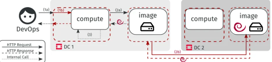
example of Figure 4, the web service on the Edge 1 site calls the chat service.

This paper sketches a new approach for rule-based reasoning, enabling distributed rule evaluation on edge nodes and reducing the latency for IoT applications while avoiding the

L’objectif de cette thèse est de concevoir des modèles et de développer des approches d’optimisation pour résoudre le problème de planification intégrée des

L’archive ouverte pluridisciplinaire HAL, est destinée au dépôt et à la diffusion de documents scientifiques de niveau recherche, publiés ou non, émanant des