HAL Id: hal-00876288
https://hal.archives-ouvertes.fr/hal-00876288
Submitted on 24 Oct 2013
HAL is a multi-disciplinary open access
archive for the deposit and dissemination of
sci-entific research documents, whether they are
pub-lished or not. The documents may come from
teaching and research institutions in France or
abroad, or from public or private research centers.
L’archive ouverte pluridisciplinaire HAL, est
destinée au dépôt et à la diffusion de documents
scientifiques de niveau recherche, publiés ou non,
émanant des établissements d’enseignement et de
recherche français ou étrangers, des laboratoires
publics ou privés.
Chaillet
To cite this version:
Ioan Alexandru Ivan, Adrian Ciubotariu, Cédric Clévy, Philippe Lutz, Nicolas Chaillet. Duo-bimorph
actuator made of PMN-PT [011] : 3D modeling, development and characterization.. IEEE/ASME
International Conference on Advanced Intelligent Mechatronics, AIM’13., Jan 2013, Australia.
pp.140-145. �hal-00876288�
Abstract— This paper reports the development of a
duo-bimorph cantilevered actuator made of PMN-PT material and intended for large-stroke micro-scale manipulation. The principle of operation is piezoelectric, but with a series of material-induced particularities: PMN-PT is reputed for its very high piezoelectric and electromechanical coupling characteristics, but exhibits a lower coercive field which prevents driving in a fully bipolar manner. Instead of the uniaxial [001] plate, by using the anisotropic [011] cut, a positive transverse d31 piezoelectric coefficient may be exploited. This allows the extension of the structure with the applied voltage, which is particularly beneficial for micro-gripping. After an introductory part in piezo-materials and duo-bimorph structures, a comprehensive static three-dimensional displacement modeling is provided by means of constitutive matrix equations. The actuator micro-manufacturing is presented, followed by the experimental characterization. Compared to the classical PZT structures, the actuation is increased by a factor of two, up to 600 µm in the transversal plane and up to 20 µm longitudinally. Some perspectives related to 3 DoF (Degrees of Freedom) micro-manipulation tasks are finally approached.
I. INTRODUCTION
Nowadays, the microsystems functional requirements keep ever increasing. Many products notably require the integration of smart materials for actuation and/or sensing purposes. Applications such as in the Micro-Electro-Mechanical-Systems (MEMS) [1], biomedical [2][3], microrobotics or microgripping [4] must take advantage of highly integrated, very accurate and highly dynamic smart materials.
Among the smart materials, piezoelectric ones are widespread because they enable generating accurate, multi DoF motions with large bandwidth and forces. Despite these advantages, new piezo materials are being developed to obtain increased performance. For example, studies in the microrobotic and micro-assembly fields have shown that DoF must be placed closer to the manipulated object, i.e. dexterous microgripper are desirable with respect to the basic grippers moved by robotic structures [5][6]. Many piezoelectric microgrippers have been proposed, some of them proposing 4 DoF [7] (both fingers actuated up and down supplementary to the open and close motions), thus offering increased gripping
Authors are with the FEMTO-ST Institute (UMR CNRS 6174) - UFC/ENSMM/UTBM, AS2M Department, 24 Rue Alain Savary, 25000 Besancon, France (phone: +33-381-402-803; fax: +333-381-853-998; e-mail: {alex.ivan, adrian.ciubotariu, cclevy, plutz, nicolas.chaillet}@ femto-st.fr).
I.A. Ivan and D.A. Ciubotariu are also with Valahia University of Targoviste, FIE/ICSTM, B-dul Unirii 18-20, 130082 Targoviste, Romania; e-mail: [email protected].
dexterity. Innovative materials or manufacturing techniques (PMN-PT, sol-gel etc.) present several advantages over the commonly-used sintered piezo-ceramics (PZT), especially in terms of displacement range or integration. This paper will focus on the use of PMN-PT materials because they are capable of much larger actuation [8] and more degrees of freedom for similar free space (extremely high ferroelectric properties for all directions).
PMN-PT materials are quite recent (available since the 2000’s) and their behavior is still to be fully investigated in applications. PMN-PT actuators can be manufactured using microfabrication techniques [9] and can thus be structured easier than other kinds of piezo-materials [10]. This paper will continue the aim at studying the PMN-PT material properties and particularities, this time investigating the particularly interesting anisotropic cut in the [011] poling direction. The difference to the regular and uniaxial [001] cut, is that the [011] PMN-PT exhibit a positive transverse piezoelectric coefficient in the X direction and an even larger, negative coefficient in the Y crystalline direction. This particularity allows the extension of the beam structure with the applied voltage rather than compression, which is particularly beneficial for micro-gripping.
This paper case of study is a duo-bimorph cantilever beam, which is an interesting multi DoF test-bed to compare the PMN-PT materials with more classical ones like PZT. Provided the advantage of positive transverse piezoelectric coefficient in [011] and the extension of the structure to the applied voltage, the third longitudinal axis could be exploited in a micro-gripper configuration.
The paper is structured as follows: Section II will present the 3D displacement modeling aspects in an analytical constitutive form. Section III will display the experimental results inducing model validation and coupling issues. A conclusion highlighting the specificities and advantages of PMN-PT will end the paper.
II. DUO-BIMORPH MODELING A. Presentation of the duo-bimorph structure
A duo-bimorph actuator is made up of two layers of piezoelectric material soldered or bonded together, like a regular bimorph actuator. The difference consists of having five electrodes instead of three, like in Figure 1. Thus, by using a proper combination of signals, displacement in Y direction becomes possible.
Duo-bimorph actuator made of PMN-PT [011]: 3D modeling,
development and characterization
Ioan Alexandru Ivan, Member, IEEE, Dragos Adrian Ciubotariu, Cédric Clévy, Philippe Lutz,
Figure 1. Structure of the duo-bimorph actuator, the electrode convention and the working referential system.
Depending on the two layers poling direction and on the piezoelectric transverse coefficients signs, a strict convention must be established for the applied voltages as shown in Figure 2.
Figure 2.a) Same direction poling duo-bimorph (side view); b) opposite-direction poling duo-bimorph. The difference consist in the applied voltages
signs to obtain the desired displacement.
B. Modeling of the duo-bimorph
The first modeling of a duo-bimorph piezo-beam has been performed in [11]. Provided the PMN-PT particularities, the constitutive equations should be updated for PMN-PT because of the lower (limited) coercive field [8]. Still provided the large actuation, adding the modeling of the duo-bimorph in the third longitudinal X-direction is also preferable. Finally, the end-effector modeling will be added.
As already noticed in Figure 1, the duo-bimorph displacement is controlled by applying high voltage signals to the 4 electrodes (VE1, VE2, VE3, and VE4). The complete 3D
voltage-to-displacement model may be expressed as follows:
E Z Y X V S F C ) (
(1) Where δX, δY, δZ, are the deflections on the X, Y and Zaxes, VE is the array of voltages across the electrodes, C is the
piezo-bimorph constitutive matrix and F is the end-effector displacement matrix which is effective only transversally:
4 3 2 1 E E E E E V V V V V 0 0 0 0 0 0 33 22 11 C C C C 0 0 0 0 0 0 0 33 22 F F F (2)(3)(4)
The coefficients C11 to F33 are calculated starting from the
strain-charge constitutive matrix of the piezoelectric effect. Due to space restrictions, only the results are shown:
p
h
L
d
C
4
31 11
(5)By using the modeling from [11] we derived:
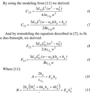
3 11 2 0 2 2 31 22 4 ) ( 3 w As w w L d C p (6) w Bs h h w w L d C p g p 11 0 2 31 33 2 ) )( ( 3 (7)
And by remodeling the equation described in [7], to fit the duo-bimorph, we derived:
3 11 2 0 2 2 31 22 2 ) ( 3 w As w w L d F p ee (8) w Bs h h w w L d F p g p ee 11 0 2 31 33 ) )( ( 3 (9) Where [11]: g g p h E s h A p 11 2 (10)
3 11 2 2 4 6 3 2 g g p p g g p h E s h h h h h B p (11)Table 1 explains and provides values for all the above dimensions, parameters and coefficients. In the case of a beam cut along Y-direction, s11p and d31 coefficients should be
replaced by s22p and d32.
TABLE I. THE CONSTITUTIVE EQUATIONS PARAMETERS.
Parameter Description Value
L Piezo-beam length 23 mm
Lee End-effector length 4 mm
w Total beam width 600 µm
w0 Groove width (electrodes gap) 100 µm
hp Piezo-layer thickness 200 µm
hg Adhesive-layer thickness 10 µm
d31 Transverse piezo coefficient 456,55 pm/V
s11p Piezo elasticity coefficient 69 x 10-12 m2/N
Eg Young’s modulus of adhesive 1 x 10¹² N/m2
S is the sign matrix depending on: the electrodes notation,
piezoelectric material poling direction (Figure 2) and the transverse piezoelectric coefficient (d31 or d32) sign.
Considering the electrode identification shown in Fig.1, the poling in opposite direction of the two PMN-PT layers (as shown in Fig.2.b) and a positive transverse piezoelectric coefficient, conditions which were in our experimental case, the sign matrix, S is as follows:
1 1 1 1 1 1 1 1 1 1 1 1 S (12)
We shall make the following notation of three voltage signals:
4 3 2 1 S 4 1 E E E E Z Y X V V V V V V V V (13)
By combining expressions (1) with (13), we get the following linear, theoretically decoupled system:
δ Z Y X Z Y X V F C V V V F C ) 4( ) ( 4
(14) This expression (model) can be easily reverted to estimate the required voltage for a given displacement: Z Y X Z Y X F C V V V
1 ) ( 4 1 (15)In our case, provided (13), we get the straightforward reverse relation: Z Y X Z Y X T E E E E V V V V V V S V V V V 1 1 1 1 1 1 1 1 1 1 1 1 4 3 2 1 (17)
From (15) and (17) we get:
Z Y X T E E E E F C S V V V V 1 4 3 2 1 ) ( 4 1 (18)
In the case of piezoelectric materials, the operating voltage must be greater than the one related to the coercive field value, called VC = -EChp.
For a 200 µm plate, we experimentally determined the coercive voltage values. These are as follows:
o in the case of PZT, VC = -150V;
o in the case of PMN-PT [001], VC = -45V;
o in the case of PMN-PT [011], VC = -15V.
Figure 3. Unipolar operation mode in the case of coercive field limitation. Example for Z-displacement
a) operating voltage VE derived upon applying H(x) Heaviside operator b) resulting displacement as a function of the input voltage variable c), d) same characteristics, but with VC=0V (pure unipolar operation)
As noticed, in the case of PMN-PT the│VC│is much
lower than in the case of PZT. Therefor we have to restrict the reverse operating field to a safety zone. We call this type of driving: unipolar operation (Figure 3).
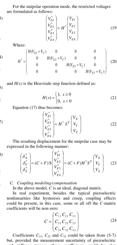
For the unipolar operation mode, the restricted voltages are formulated as follows:
4 3 2 1 * * 4 * 3 * 2 * 1 E E E E E E E E V V V V H V V V V (19) Where: ) ( 0 0 0 0 ) ( 0 0 0 0 ) ( 0 0 0 0 ) ( 3 3 2 1 * C E C E C E C E V V H V V H V V H V V H H (20)
and H(x) is the Heaviside step function defined as:
0 , 0 0 , 1 ) ( x x x H (21)
Equation (17) thus becomes:
Z Y X T E E E E V V V S H V V V V * * 4 * 3 * 2 * 1 (22)
The resulting displacement for the unipolar case may be expressed in the following manner:
Z Y X T E E E E Z Y X V V V S H F C V V V V F C )S ( ) ( * * 4 * 3 * 2 * 1 * * * (23) C. Coupling modeling/compensation
In the above model, C is an ideal, diagonal matrix. In real experiment, besides the typical piezoelectric nonlinearities like hysteresis and creep, coupling effects could be present, in this case, some or all off the C-matrix coefficients will be non-zero:
33 23 13 32 22 12 31 12 11 C C C C C C C C C C (24)
Coefficients C11, C22 and C33 could be taken from (5-7)
but, provided the measurement uncertainty of piezoelectric and stiffness tensors, these coefficients could be also identified experimentally. The remaining unknown coefficients, called coupling coefficients can be identified empirically.
III. EXPERIMENTS WITH PMN-PT DUO-BIMORPH A. Manufacturing of the micro-actuator featuring positive d31 coefficient in PMN-PT [011] cut
The micro actuator is fabricated starting from two plates of PMN-PT manufactured by TRS Technologies, each 200
µm thick, bonded using a silver-based EPO-TEK® H22 adhesive, 10-20 µm thick.
Individual beams of 600 µm wide, 27 mm long and 410 µm thick were precisely cut using a saw-dicing machine. Prior to this final cut, superficial grooves were patterned on the opposite faces, as shown in Figure 1, These grooves, separating the electrodes E1 from E2 and E3 from E4, are 100
µm wide and 40 µm deep. The middle electrode is the connected to the common ground (GND).
The duo-bimorph beam was aligned in place on a PCB (printed circuit board and glued to the bottom face (E3-E4).
The remaining active actuator length is 23mm. The connection between the PCB and electrodes has been done by wire-bonding.
The end-effectors, or MEMS fingertips, are microfabricated in pairs in a silicon-on-insulator (SOI) wafer shaped by Deep-RIE etching whose details are shown in [12]. The top silicon layer is 10µm thick and the end-effectors allow microgripping objects in the 10 to 100 μm range (Figure 4, detail).
The MEMS fingertips are composed of a thick part (413 μm), to be fixed on the actuators, and a thin part (10 μm) with a suitable shape to manipulate the objects. The central part between the two arms is designed to keep the alignment and the gap of the end-effector tips during the assembly process. This central part is removable by means of breakable links present on each side.
Figure 4. Experimental setup: actuators fixture on the left and the microscopy camera on the right.
B. Experimental setup
An imaging setup (Guppy® camera F-036 with 1-7X video tube and 5X long distance Mitutoyo® objective) was placed in front of the actuators to track the displacement of the tips in Y-Z plane (Figure 5). This camera was calibrated in µm using a reference target. The tip displacement position was calculated using image processing software.
Figure 5. – Image as seen through the Guppy® camera.
Alternately this setup was also used to measure the X-displacement.
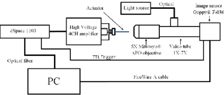
The camera was precisely triggered by a dSPACE® 1103 rapid control prototyping controller. A custom-made,
high-voltage amplifier was connected between the controller and the piezoelectric actuator (Figure 6).
Figure 6. Experimental setup for duo-bimorph action and analysis.
C. Modeling validation
In order to ascertain whether the model is accurate, certain coefficients needed to be experimentally determined, such as d31 and d32. These transverse coefficients were
calculated separately on the initial plain rectangular plates of 20x25mm2 using the same image processing method.
As known [8], PMN-PT [011] has a positive value for d31
and a value for d32 which is approximately -1/3d31. A batch
of six plates were individually tested, d31 values ranged from
420 pm/V to 485 pm/V and d32 ranged from -1000 pm/V
to -1360 pm/V. Table II shows the average values. For comparison, we also measured the d31 and d32 coefficients of
some PMN-PT [001] and PZT-5H plates. Coefficient s11 = 69
x 10-12 m2/N has been taken from [13].
TABLE II. EXPERIMENTAL VALUES FOUND FOR PMN-PT AND PZT PIEZOELECTRIC MATERIALS
Material type Transverse piezoelectric coefficients
d31 d32
PZT-5H -274 pm/V -274 pm/V
PMN-PT [001] -924 pm/V -1036 pm/V
PMN-PT [011] +456 pm/V -1180 pm/V
The experiment was conducted as follows: voltage was applied in step values of 140V, firstly on each electrode E1 to E4 to obtain the displacements in the four quadrants (Figure
7). Then, combined step voltages in VY and VZ were applied
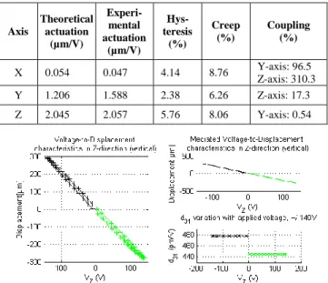
to observe the creep behavior in the transversal plane (Figures 9,10). Finally, sine waveforms were applied to observe the hysteresis and the coupling in all the three directions, including the longitudinal X-axis (Figures 11,12,13). Notice that, to simplify the conditions, only the fully unipolar driving was applied, meaning two electrodes at a time (as in Figure 3.c,d). Table III groups the most relevant experimental results compared with the associate theoretical modeling. Nonlinearities, such as hysteresis, creep and inter-electrode coupling are also numerically presented.
A fair agreement between the analytical modeling and experimental data can be concluded meaning that the user could rely on the provided 3D displacement static mathematical model in his designs.
The nonlinear behavior in terms of creep and hysteresis is under 9%, a very good figure for the PMN-PT material, comparing it to PZT where such nonlinearities are close to 20%.
The actuator has been tested up to ±140V transversally and up to 300V longitudinally. We may notice form Figure 11 that at 300V (15 kV/cm) saturation is far from being reached. This means that such an actuator is viable for a 3D manipulation.
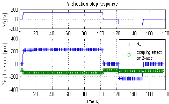
On the other hand, an unwanted coupling can be noticed, which manifests differently along the three axes. The weakest coupling, almost non-existing, is observed on Y-axis when actuating along Z-axis (Figures 11 and 14). This is because the layers are independently actuated. The coupling in Z-axis, when actuating in Y-direction, is larger due to a series of causes which will be detailed in the next paragraph. The largest concern is upon actuating longitudinally (in X-direction). Due to the fact that the longitudinal extension (0.047 µm/V) is much smaller than the transversal flexure (~2 µm/V), coupling in Z-direction was found to exceed 300%, which will require compensation. For instance, by unbalancing the X-voltage by ±10V, the unwanted Z-displacement coupling will be cancelled.
The noticed experimental coupling is, in effect, a combined consequence of several factors. Firstly, there is an inherent difference between the two layers material constants. From Figure 15 we notice a transverse piezoelectric coefficient difference of over 7%. Secondly, in each layer, as three electrodes share a common piezo-element, the electrical field distribution is not decoupled (Figure 9). And thirdly, the cantilevers are not symmetrically clamped (only the bottom layer is bonded) which also induces a certainly unbalanced flexure.
a) b)
c) d)
Figure 7. Y-Z displacement resulting from step signals applied to individual electrodes: a) E1 only, b) E2 only, c) E3 only, d) E4 only.
Figure 8. Representation (FEM simulation) of electric field lines in on of the piezo-layers. Notice the field distribution asymetry.
Figure 9. Step input voltage applied on Y-axis. For conveninece, the Z-displacement curve was offset by -100 µm.
Figure 10. Step input voltage applied on Z-axis. For conveninece, the Y-displacement curve was offset by -100 µm.
The coupling effect can be better observed and quantified when applying sine wave signals along the three axes (Figure 11 – X-axis, Figure 12 – Y-axis and Figure 13 – Z-axis).
Figure 11. Displacement hysteresis loop in X-axis and the coupling effect in the Z and in the Y axis .
Figure 12. Displacement hysteresis loop in Y-axis and the coupling effect in the Z-axis.
Figure 13. Displacement hysteresis loop in Z-axis and the coupling effect in the Y-axis.
TABLE III. THEORETICAL AND EXPERIMENTAL RESULTS.DATA OBSERVED IN A FULLY UNIPOLAR OPERATION MODE (CF.FIGURE 3.C AND D) Axis Theoretical actuation (µm/V) Experi-mental actuation (µm/V) Hys- teresis (%) Creep (%) Coupling (%) X 0.054 0.047 4.14 8.76 Y-axis: 96.5 Z-axis: 310.3 Y 1.206 1.588 2.38 6.26 Z-axis: 17.3 Z 2.045 2.057 5.76 8.06 Y-axis: 0.54
Figire 14. Applied voltage on the top layer (E1, E2) results in a downward (-Z) displacement (green); The top layer calculated d31 is 444 pm/V. Applied voltage on the bottom layer (E3, E4) results in a upward (+Z)
displacement (black); The bottom layer calculated d31 is 477 pm/V.
IV. CONCLUSIONS
This paper has presented the design, modeling, development and characterization of a duo-bimorph cantilevered actuator made of the anisotropic PMN-PT poled in [011] crystalline direction. One contribution of the paper is in adding the longitudinal analytical modeling to the existing literature [7][11]. This static displacement modeling also included a microfabricated end-effector, usually attached to the free end, a piece which plays the microgripping role in a microassembly task [12]. PMN-PT exhibits much larger piezoelectric coefficients, which significantly increase the actuation range. Therefore, we chose to develop a duo-bimorph actuator, whose fabrication in detailed in the paper. The approach was twofold: to validate the model and to investigate the material behavior.
The advantage of the [011] cut PMN-PT consists in its positive transverse piezoelectric coefficient which allows the extension of the structure with the applied voltage by over 20µm for an active structure of 23mm, in a good agreement with the model. The in-plane actuation increased to 600µm (twice that of PZT), still without saturating the material. The piezoelectric nonlinearities (static hysteresis, creep) were
investigated and found to be lower than 9%. Limitations include the unipolar operation mode, due to the material low coercive field, and a certain unwanted coupling between the axes, due to the duo-bimorph structure.
As perspectives, a 3D-capable microgripper could be designed (we already assembled and pictured a first version of the microgripper, which will be treated in a future paper). The coupling has been quantified and due to the modeling complexity will be treated separately.
V. ACKNOWLEDGEMENTS
These works were partly supported under the National Projects UEFISCDI PN-II-RU-TE-2011-3-0299 (ADMAN), the ANR-11-EMMA-006 (MYMESYS) and the Franche-Comte region. We acknowledge the FEMTO-ST technological facility, the LAbex Action (smart systems) and particularly the technical support of David Guibert and of Marius Ionita.
REFERENCES
[1] D. Tolfree and M. J. Jackson, (2006), Commercializing
Micro-Nanotechnology Products. CRC Press.
[2] K. Aljasem, L. Froehly, A. Seifert, and H.Zappe, (2011) “Scanning
and tunable micro-optics for endoscopic optical coherence tomography,” Journal of Microelectromechanical Systems, vol. 20, pp.
1462 – 1472.
[3] J. Sun, and H. Xie, (2011) "MEMS-Based Endoscopic Optical
Coherence Tomography", International Journal of Optics, vol. 2011,
no. 825629.
[4] J. Agnus, N. Chaillet, C. Clévy, S. Dembélé, M. Gauthier, Y. Haddab, G. Laurent, P. Lutz, N. Piat and M. Rakotondrabe Robotic
Microassembly and micromanipulation at FEMTO-ST, Journal of
Micro-Nano Mechatronics, Accepted (to appear 2013).
[5] N. Chaillet and S. Régnier, Microrobotics for micromanipulation, Wiley (2010).
[6] B. Komati, K. Rabenorosoa, C. Clévy and P. Lutz, Automated Guiding
Task of a Flexible Micropart Using a Two-Sensing-Fingers Microgripper, IEEE Transactions on Automation Science and
Engineering (T-ASE), Accepted (To appear, 2013).
[7] R. Pérez, J. Agnus, C. Clévy, A. Hubert, N. Chaillet, Modelling,
fabrication and validation of a high performance 2-DoF piezoactuator for micromanipulation, IEEE/ASME Transactions on Mechatronics,
10(2), pp. 161-171, april 2005.
[8] I. A. Ivan, M. Rakotondrabe, J. Agnus, R. Bourquin, N. Chaillet, P. Lutz, J. C. Ponçot, R. Duffait, O. Bauer, Comparative material study
between PZT ceramic and newer crystalline PMN-PT and PZN-PT materials for composite bimorph actuators, Reviews on Advanced
Materials Science (RAMS), Vol.24(1), 2010.
[9] I.A. Ivan, J. Agnus, M. Rakotondrabe, P. Lutz, N. Chaillet, ”Microfabricated PMN-PT on Silicon cantilevers with improved static
and dynamic piezoelectric actuation: development, characterization and control”, IEEE/ASME International Conference on Advanced
Intelligent Mechatronics (AIM2011), ISBN 978-1-4577-0837-4, pp. 403-408, Budapest, Hungary, 2011
[10] I. A. Ivan, J. Agnus and P. Lambert, ”PMN-PT piezoelectric material
micromachining by excimer laser ablation and dry etching (DRIE)”,
Sensors and Actuators: A - Physical, DOI:10.1016/j.sna.2011.09.015, Vol. 177, pp. 37-47, 2012.
[11] P. De Lit, J. Agnus, N. Chaillet, “The constitutive equations of a
piezoelectric duo-bimorph”, Proceedings of the IEEE International
Symposium on Assembly and Task Planning, pp. 1-6, 2003.
[12] J. Agnus, D. Hériban, M. Gauthier, V. Pétrini, “Silicon end-effectors
for microgripping tasks”, Precision Engineering, Vol. 33 (4), pp.542–
548, 2009.
[13] Y. M. Kim, S. H. Lee, H. Y. Lee, and Y. R. Roh, “Measurement of all
the material properties of PMN-PT single crystals grown by the Solid-State-Crystal-Growth (SSCG) method”, 2003 IEEE Ultrasonics Symp.,